JUKI MB-373 Series User manual

1. SPECIFICATIONS
MB-373
MB-377
Other specifications are same as those of MB-373.
−1−−1−
1
2
3
4
5
6
7
8
9
10
11
Sewing speed
Number of stitches
Amount of feed
Stitching pattern
Button size
Needle bar stroke
Needle
Automatic thread trimmer
Presser lifter
Stop-motion unit
Power supply
Max. 1,500 rpm Normal speed 1,300 rpm
8, 16, and 32 stitches
(6, 12 and 24 stitches are also possible by changing the cam.)
Crosswise feed 2.5 to 6.5 mm
Lengthwise feed 0, 2.5 to 6.5 mm
コ-shape, Z-shape, Π-shape, and X-shape
10 to 28 ø mm
48.6 mm
TQ x 7 #16 (#14 to #20)
Interlocked with the presser lifter.
Consists of a fixed knife and a moving knife.
Automatically operated (Pedal-system is also available.)
Automatically operated (equipped with speed slowing device)
200 W (1/4 HP) single- or three-phase
1
2
Stitching pattern
Needle
コ-shape, Z-shape, and X-shape
TQ x 1 #16 (In case of attachments for medium button (Z202) and
large button (Z201) TQ x 7 #16, #14 to #20)

−2−
(1) Height of the needle bar
The upper engraved line should be aligned with the bottom of lower bushing 3when the needle bar is
at its lowest position.
Standard needle for MB-373 : TQ x 7
Standard needle for MB-377 : TQ x 1
2. STANDARD ADJUSTMENT
(2) Positioning the needle and the looper
1) Looper timing
When the needle bar is ascending from its lowest
position and the lower engraved line on the needle
bar is aligned with the bottom of the lower bushing,
the looper’s blade point should coincide with the
center of the needle. (When the needle bar is
ascending.)
2) Clearance between the needle and looper
The clearance is 0.01 to 0.1 mm when the looper’s
blade point coincides with the center of the needle.
3) Clearance between the needle guide and needle
The clearance between needle guide 6and
needle is 0 to 0.1 mm when the needle bar is at its
lowest position.
Standard Adjustment
For TQ x 1
For TQ x 7
Engraved line
Height of the needle bar
Looper timing
Lower bushing
Engraved line
Clearance between needle and looper
0.01 to 0.1 mm
Looper’s blade point
Looper’s blade
point coincides
with center of
needle.
Clearance between needle and looper
0 to 0.1 mm
3
6
8

−3−
™Turn the hand wheel by hand and loosen
screw 1in the Fig. A in the thread take-
up lever to adjust so that the upper
engraved line of the two engraved lines
on the needle bar aligns with the bottom
of lower bushing 3when the needle bar
is at its lowest position.
For the old type sewing machine, in
addition, adjust the position so that
needle clamp screw 4enters the slot of
lower bushing 3as illustrated in Fig. B
when the needle bar is at its highest
position.
Following needles are equipped at the
time of delivery.
MB-373 : Standard needle TQ x 7 #16
MB-377 : Standard needle TQ x 1 #16
MB-377 / Z201 : TQ x 7 #20
MB-377 / Z202 : TQ x 7 #18
™If needle bar 2is too high, skipped
stitches will be produced.
If the needle bar is too low, the
needle will come in contact with the
looper.
1) Adjusting the looper timing
™Loosen two screws 5in the looper and cam sleeve and
adjust in the rotating direction of the looper and cam sleeve
so that the looper’s blade point aligns with the center of
the needle when the lower engraved line of the needle
bar is aligned with the bottom of the lower bushing. Then
tighten the screws.
2) Clearance between the needle and looper
Loosen two screws 7in the looper suppot ring and adjust
in the longitudinal position of the looper when the looper’s
blade point is aligned with the center of the needle. Then
tighten the screws.
3) Clearance between the needle guide and needle
Loosen screw 8in the needle guide and adjust in the
longitudinal position of the needle guide so that the clearance
between needle guide 6and needle should become 0 to
0.1 mm when the needle bar is at its lowest position.
™If the clearance between the needle
and looper is too excessive, it is
likely to produce skipped stitches.
If the clearance is too small, in
accordance with the material used,
the needle will come in contact with
the looper resulting in needle
breakage and looper’s blade point
breakage.
™For thick materials and overlapped
sections, adjust the clearance
between the needle guide and
needle so that the needle guide
touches the needle by 0.1 to 0.2
mm.
Fig. A
Fig. B
Adjustment Procedures Results of Improper Adjustment
1
2
34
34
5
7

−4−
Standard Adjustment
(3) Timing the travel of the yoke slide
1) Crosswise travel timing of the yoke slide
The height of the ascending needle bar when the yoke slide
advances and begins to travel from the left to righgt is as
shown in the table below.
2) Lengthwise travel timing of the yoke slide
The yoke slide begins to go back immediately after the
blade point of the looper has passed the thread triangle.
And, it is good for the looper to go back like a slant line of
the movement of the triangle.
3) Lengthwise positioning of the yoke slide
Position the yoke slide so that the blade point of the looper
passes through the center of the thread triangle. (Use a 4-
hole button, 9 or 10 stitches for positioning.)
Model
MB-373
MB-377
Thread
Cotton #50
Tetoron #20
Needle
TQ x 7
TQ x 7
TQ x 1
TQ x 7
Needle bar height
14 to 17 mm
14 to 18 mm
4 to 8 mm
14 to 18 mm
14 to 17 mm
Needle bar
Blade point of looper

−5−
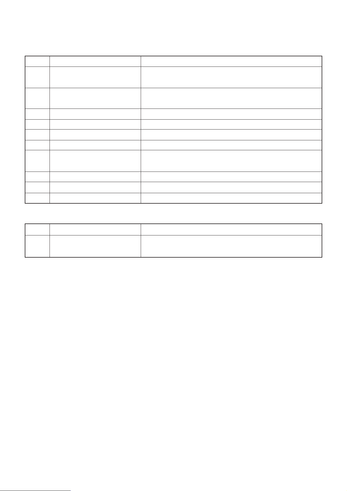
™For adjusting the timing of the travel of the yoke slide, align
the engraved marks of the loop positioning finger cam and
the triangle loop positioning finger cam with the engraved
mark of the cam and looper sleeve after the adjustment of
the looper so that the engraved marks are on a straight line.
Then temporarily tighten the screws.
1) Adjust the crosswise travel timing of the yoke slide in the
rotational direction of the triangle loop positioning finger cam.
When the timing is higher than 58 mm (48 mm), adjust the
timing in the rotational direction of the cam, and when it is
lower than 53 mm (43 mm), adjust the timing in the reverse
rotational direction of the cam.
The center of the cam is aligned with the center of the
positioning finger yoke slide in the longitudinal position of
the cam.
2) Adjust the lengthwise travel timing of the yoke slide in the
rotational direction of the loop positioning finger cam.
For the triangle movement of the yoke slide, it is good for
the yoke slide to go back like a slant line. When the yoke
slide goes back like a swollen line, adjust the cam in the
reverse rotational direction, and when it goes back like a
hollow line inside, adjust the cam in the rotational direction.
3) Adjust the longitudinal position of the yoke slide by moving
the loop positioning finger cam in the lengthwise direction.
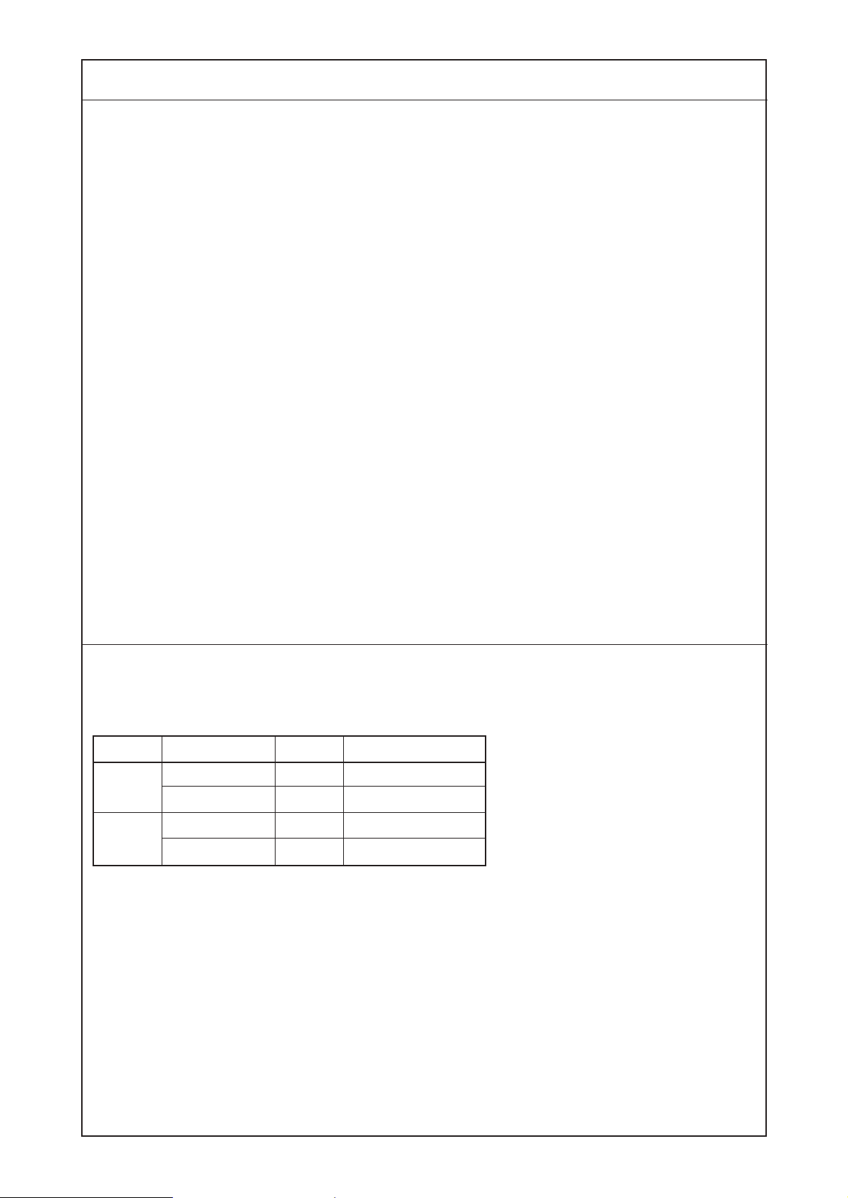
™If the triangle loop positioning finger
cam begins to travel too late, thread
breakage, thread remaining, baloon
stitch, and insufficient tightness of
stitches will result.
On the contrary, if it begins to move
too early, the needle will come in
contact with the yoke slide.
™If the loop positioning finger cam
begins to go back too early, the
retreat of the yoke slide will become
like a swollen line and the looper
will hook the thread twice.
™On the other hand, if it begins to
retreat too late, its retreat will
become like a hollow line and the
needle will come in contact with the
yoke slide.
™If the longitudinal position of the
yoke slide is improper, the looper
will hook the thread twice or the
needle will come in contact with the
yoke slide.
Adjustment Procedures Results of Improper Adjustment
Yoke slide retreats like
a swollen line.
Yoke slide retreats like
a hollow line.
Loop positioning
finger cam
Looper
Engraved mark
Triangle loop positioning
finger cam Cam and looper sleeve

−6−
(4) Positioning the cloth feed cam
The engraved point of the outer circumference of the cloth feed cam should be aligned with the pivot
fixed on the bed at the time of stop motion.
(5) The floating timing of the tension disc No. 2
The height of the ascending needle bar at the time of the floating timing of the tension disc No. 2 is as
shown in the table below.
Standard Adjustment
Lengthwise feed cam Crosswise feed cam
Model
MB-373
MB-377
Thread
Cotton #50
Tetoron #20
Needle
TQ x 7
TQ x 7
TQ x 1
TQ x 7
Needle bar height
53 to 56 mm
54 to 57 mm
44 to 47 mm
54 to 57 mm
53 to 56 mm
Needle bar
Nut
Screw driver

−7−
™Align the engraved point on the cam with the pivot on the
bed at the position of stop motion. Then, tighten the setscrew
of cam.
After the adjustment, turn the stop motion pulley by hand
and confirm that the button clamp stops at the distance of
about 13 mm between the top of needle and the top surface
of throat plate when the needle bar descends by means of
crosswise feed.
™If the lengthwise feed cam and
crosswise feed cam do not engage
each other, the needle moves in the
matertial used.
™For MB-377
If the position of engraved point is
not proper, the needle entry will vary
and be not likely to drop in the same
point.
→Thread is likely to be frayed.
If the position of engraved point is
moved to the rotating direction of
the cam, the needle is likely to move
in the material used when the
needle comes out of the material.
If the position of engraved point is
moved to the opposite direction, the
button clamp will be likely to
continue working until the needle
enters into the material.
™Loosen the adjusting nut of the tension post No. 2, insert a
screwdriver into the tension post No. 2, and turn the tension
post No. 2 as shown in the figure below to make adjustment.
The timing of the start of floating is when the thread tension
is lost after passing the thread through the thread tension
No. 2, holding it with fingers and turning the machine by hand.
™If the thread tension is released too
early, thread remaining and/or poor
tightness of stitches will result.
On the other hand, if the timing of
thread tension release is too late,
thread will break.
Adjustment Procedures Results of Improper Adjustment
0.8 mm
A
Rotating direction of cam
Nut
Screw driver
Timing of start of floating
is when thread tension is
lost at the time of needle
bar ascending.

−8−
(6) Lift and pressure of the button clamp
1) Lift of the button clamp
AMB-372 : 12 mm
MB-373 : 9 mm
MB-377 : 8 mm for コ-shape
8 mm for Z -shape
10 mm for X -shape
2) Pressure of the button clamp
Adjust the position of pressure adjusting nut 1to 4 to 5 mm from the lower side of the screw section of
pressure adjusting bar 2.
(7) Thread tension disc No.1
Adjust so that the thread tension disc No.1 floats by 1 mm at the time of stop motion.
Also, the thread tension should move during the sewing operation.
Standard Adjustment
4 to 5 mm
Floats by 1 mm at the time of stop motion
Thread tension disc floating plate
3
4
A
1
2

−9−
1) The knife moves in accordance with the lifting of the button
clamp. Therefore, the length of the remaining thread on the
wrong side of a fabric depends upon the height of the button
clamp at which the thread is trimmed. (In case of MB-373/
377)
For MB-372, the lifting amount of the button clamp is higher
as the button clamp cuts by its lifting force the thread lying
on the looper when the button clamp ascends at the time of
stop motion.
Loosen hook setscrew 3and move hook 4up or down for
adjustment.
2) Make adjustment by turning pressure adjusting nut 1.
™Increasing the lifting amount of the
button clamp will increase the
length of the remaining thread.
Especially in case of MB-372,
thread tightness becomes strong at
the end of sewing resulting in thread
breakage and thread slip-off.
™If the lifting amount of the button
clamp is too low, the length of the
remaining thread will become short
resulting in thread slip-off.
™If the pressure of the button clamp
is too low, the thread end at the start
of sewing will come out on the
wrong side of the fabric unevenly
by 10 to 20 mm.
™If the floating amount is too high, the
thread tension disc keeps floating
during sewing operation resulting in
insufficient button stitching.
™If the floating amount is too low, the
thread length at the start of sewing
will become short resulting in thread
slip-off.
™Make adjustment so that the thread tension disc floats at the
time of stop motion by moving back and forth the thread
tension disc floating plate.
If the position is not proper, the disc will be likely to float
during the sewing operation.
Adjustment Procedures Results of Improper Adjustment

−10 −
(8) Positioning the thread nipper
The clearance between thread nipper 1and nipper block 2should be 0.8 to 1.2 mm while the machine
is in operation.
(In case of MB-377 : 0.4 to 0.8 mm)
(9) Positioning the stitch adjusting cam
The clearance between the roller and the recess of the cam should be 0.8 mm at the stop-motion
position.
Standard Adjustment
0.8 to 1.2 mm
0.8 mm
A
Rotating direction of cam
1
2

−11 −
™Remove the machine arm side cover (left), loosen the screw
of nipper bar block 3and move nipper bar block 4to the
right or left to perform adjustment.
™Loosen the stitch adjusting cam screw A, and turn the cam
in the rotational direction to make adjustment.
™If the impact at the time of the stop
motion is too great, increase the
clearance, and if the cam stops
before it reaches the stop-motion
position, decrease the clearance.
™If the clearance is too large, the
thread from the needle will become
too short.
™If the clearance is too small, some
kinds of thread will be broken.
Adjustment Procedures Results of Improper Adjustment
Stop-motion position
3
4

−12 −
(10) Positioning the stop motion disc and the stop motion plunger
1) The clearance between the stop motion disc and the stop motion plunger should be 2.4 mm while the
machine is in operation or at the position of 3 to 4 stitches from the position of stop-motion.
2) The clearance between the stop motion plunger lever and the stop motion plunger should be 8.5 mm.
(12) Positioning the button clamp lifting link
The clearance between button clamp lifting link 2and button clamp forked rod 3should be 0.5 to
0.8 mm while the machine is in operation.
(11) Pressure of the button clamp
A distance of 4 to 5 mm should be provided from the bottom of the pressure adjusting nut.
Standard Adjustment
8.5 mm
2.4 mm
4 to 5 mm
0.5 to 0.8 mm
2
3

−13 −
1) Perform adjustment to provide the 2.4 mm clearance after
loosening screw 1of the stop motion tripping lever. Remove
the stop motion disc pressure lever and the needle driving
pulley, insert a 2.4 mm gauge or a 3 mm wrench between
the stop motion plunger and the stop motion disc, and tighten
srew1of the stop motion tripping lever since the stop motion
lever shaft becomes loose.
2) Perform adjustment to provide the 8.5 mm clearance by the
stop motion adjusting nut 2.
™Make adjustment by turning the pressure adjusting nut.
™Make adjustment by loosening screw 1of the button
clamp lifting link lever.
™If the clearance is too large, the
button clamp will not lift at the time
of stop-motion.
If the clearance is too small, the
button clamp lifting link may come
in contact with the button clamp
forked rod during operation
resulting in producing abnormal
noise.
™Insufficient pressure will cause the
attached button to trail a 10 to 20
mm thread end of the beginning
stitch on the wrong side of the
fabric.
™If the clearance is larger than 2.4
mm, unstable entrance into the
stop-motion state will result. On the
contrary, if the clearance is smaller
than 2.4 mm, the stop motion disc
may come in contact with the stop
motion plunger during operation, or
the machine may not start.
™If the clearance is larger than 8.5
mm, the shock noise of the stop
motion is high or the stop motion
plunger comes off.
On the contrary, if the clearance is
smaller than 8.5 mm, the position
of the stop motion disc becomes
unstable at the time of stop motion.
Adjustment Procedures Results of Improper Adjustment
Stop motion
tripping lever
2.4 mm
Adjust with a 2.4 mm
gauge or a 3 mm wrench.
(Caution) Adjust the clearance when
the stop motion tripping
lever is not in the convex
section of the stop motion
cam.
1
2
1

−14 −
(13) Positioning the needle driving pulley pressure applying lever
The clearance at the stop-motion position (while the driving pulley is running idle) should be 0.2 to
0.3 mm.
(14) Positioning the thread pull-off lever
Adjust the position of thread pull-off lever 1so that the dimension between thread guide pole 4and
thread pull-off lever 1is 5 to 9 mm at the stop-motion position.
Standard Adjustment
Needle driving pulley clutch
Needle driving pulley
0.2 to 0.3 mm
MB-372 (0.8 to 0.9 mm)
MB-373 (0.2 to 0.3 mm)
MB-377 (0.2 to 0.3 mm)
5 to 9 mm
1
4

−15 −
™Loosen nut 1of the screw of the needle driving pulley
pressure applying lever and adjust by screwing in and out
screw 2.
The clearance will become larger by screwing it in.
™Perform adjustment by loosening screw 2of the nipper bar
block (rear) and moving nipper bar block (rear) 3to the right
or left.
™If the amount of movement of the
nipper bar block (rear) is too large,
at the beginning of stitching, the
thread will come out of the upper
side of the fabric. Or, the thread will
remain on the wrong side of the
fabric at second stitching.
If its amount is too small, the thread
will slip off or come out of the upper
sideofthefabricat second stitching.
Also, if its amount is too large,
thread pull-off lever 1will come in
contact with thread guide pole 4
where the thread will break.
™If the end of thread is drawn from
the arrow hole A in the button after
sewing, move nipper bar block
(rear) 3to the left. And, move it to
the right when the thread end
comes out from the arrow hole B
so that the end of thread should not
come out.
™If the clearance is too large, the
clutch will slip causing starting
difficulty.
If the clearance is too small, the
starting pedal will become heavy.
Adjustment Procedures Results of Improper Adjustment
A
B
0.2 to 0.3 mm
At the time of stop-motion position
Small Large
1
2
1
2
3

−16 −
(1) The mechanism and the name of each component of the thread trimmer
As shown in the figure below, when the button clamp lifting lever is actuated at the final stitch, the
thread trimming connecting link (rear) moves forward, causing the thread separating claw of the moving
knife to separate thread before it is trimmed by the knife.
Unlike MB-372, the stop-motion timing is delayed so that thread is trimmed after a stitch is tightened by
the thread take-up lever, eliminating the possibility of broken stitches.
(2) Clearance between the button clamp lifting lever and the adjusting screw
3. ADJUSTMENT OF AUTOMATIC THREAD TRIMMER
Standard Adjustment
Nipper bar bearing block
Nut
Screw
Button clamp lifting lever
Button clamp lifting link
Thread trimming lever base
Thread trimming lever
Thread trimming
connecting link (front)
Thread separating
claw of the moving knife
Fixed knife
Moving knife
Spring guide shaft
Spring Washer
Joint
Button clamp
lifting rod
Thread trimming connecting link (rear)
Throat plate
Cushion Thread trimming link
0.5 mm
1
2
3

−17 −
™Perform adjustment so that the clearance between the end
surface of button clamp lifting lever1and the adjusting screw
2becomes 0.5 mm. Then tighten nut 3.
Adjustment Procedures Results of Improper Adjustment

−18 −
(3) Adjusting the position of the moving knife
Adjust the position so that the distance between thread trimming connecting link (front) 1and the
edge of the slot in throat plate 2should be 12 to 13 mm when the button clamp is at its highest position
after the stop motion has been set. (For MB-377 : 10.5 to 12.5 mm) (For MB-373-11 only, adjust the
distance to 15 to 16 mm.)
(5) Installing the button clamp lifting rod
(4) Adjusting the height of the thread separating claw of the moving knife
Make adjustment so that the clearance between thread separating claw 1and looper 2should become
0.5 to 0.7 mm.
Standard Adjustment
12 to 13 mm
Gauge 12.5 mm
Tip of thread separating claw
0.5 to 0.7 mm
1
2
1
2
1
2
3
4
5
6

−19 −
™Make adjustment after tilting the machine head by loosening
two nuts 3and moving connecting screw 4back and forth.
Loosen nuts 3so that thread trimming connecting joint 5
becomes almost horizontal.
™If the above distance is too large, the timing of the thread
trimming will be delayed, and excessively long thread will
remain on the wrong side of a fabric.
On the contrary, if the distance is too small, thread will be
trimmed too early, often resulting in poor tightness of the
final stitch (easy break), trimming two threads together due
to failure of thread separation, or failure to trim thread.
™If the thread separating claw is too
high, the claw may fail to separate
the thread on the needle from that
on a fabric. As a result, thread may
not be trimmed, or the both threads
are trimmed together, causing
thread slippage from the needle in
the subsequent stitching start.
™Install button clamp lifting rod 1, spring 2, washer 3,
cushion 4, and washer 5in the numerical sequence as
shown in the figure on the previous page.
™After confirming that the stop motion is set fully, bring the
jaw of the machine arm to a close contact with the top surface
of washer
5
, leaving no play. Then, firmly tighten screw
6
.
™If the adjustment value is small (10
mm or less), the thread separating
claw will come in contact with the
counter knife or the yoke slide insert
due to overrunning of the moving
knife at the time of stop motion
resulting in breakage of the thread
separating claw.
™If the adjustment value is large (15
mm or more), the thread separating
claw will come in contact with the
yoke slide insert during machine
running resulting in breakage of the
thread separating claw.
(Caution)
The thread trimming connecting
mechanism is reset by the pressure
springs of the button clamp jaw
levers. Accordingly, the thread
trimming connecting mechanism
may not be reset when the pressure
springs are disengaged. Do not
operate the machine when making
adjustment with the pressure
springs disengaged.
™Make adjustment by bending thread separating claw 1.
Adjustment Procedures Results of Improper Adjustment
3
4
5

−20 −
(1) The mechanism and the name of each component of the knot-tying
As shown in the figure below, when the machine is running, the stitch adjusting cam rotates and the
thread bind arm roller rides over the thread bind notch attached to the stitch adjusting cam making the
thread bind plate actuate by means of the respective links to hook thread. The slack portion of the
hooked thread will be tightened by the thread wring lever at the time of stop motion.
(2) Positioning the knot-tying arm stopper
4. ADJUSTMENT OF KNOT-TYING MECHANISM (EXCLUSIVE FOR MB-377)
Standard Adjustment
Tip of thread bind plate Thread to be
hooked
Looer
Thread wring lever
Thread bind plate
Connecting plate (small)
Thread bind lever
Thread bind arm stopper
Connecting plate (large)
Thread bind link
Thread bind arm
Thread bind
notch
Thread bind
arm roller
Stitch adjusting cam
1 to 1.5 mm
1
This manual suits for next models
1
Table of contents
Other JUKI Sewing Machine manuals

JUKI
JUKI LU-1560N User manual

JUKI
JUKI AMS-221ENTS Manual

JUKI
JUKI LU-2810 Series User manual

JUKI
JUKI LK-1900B series Quick start guide

JUKI
JUKI L-60HR-C User manual

JUKI
JUKI AKANE MO-3000QVP User manual

JUKI
JUKI DLU-5494N-7 User manual

JUKI
JUKI LU-1510 Quick start guide

JUKI
JUKI 7000 User manual

JUKI
JUKI SC-500 Quick start guide

JUKI
JUKI DDL-8000AS User manual

JUKI
JUKI APW-895N/IP-420 Assembly instructions

JUKI
JUKI LBH-772NV-1 User manual

JUKI
JUKI DX-2000QVP User manual

JUKI
JUKI DLU-5490N User manual

JUKI
JUKI HZL-12Z User manual

JUKI
JUKI ASN-690 User manual

JUKI
JUKI DDL-8100e User manual

JUKI
JUKI HZL-70HW-B User manual

JUKI
JUKI JTR-DDL9000B/PPA User manual