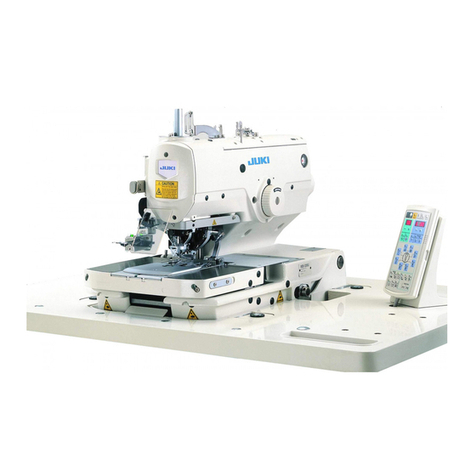
JUKI ACF-172-1790 Quick start guide

R
ENGINEER’S MANUAL
40018329
No.E360-00
1-Needle, Lockstitch
Automatic buttonholing Machine
ACF-172-1790

PREFACE
This Engineer’s Manual is written for the technical personnel who are responsible for the service and maintenance
of the machine.
The Instruction Manual for these machines intended for the maintenance personnel and operators at an apparel
factory contains operating instructions in detail. And this manual describes “Standard Adjustment”, “Adjustment
Procedures”, “Results of Improper Adjustment”, and other important information which are not covered by the
Instruction Manual.
It is advisable to use the relevant Instruction Manual and Parts List together with this Engineer’s Manual when
carrying out the maintenance of these machines. Further, refer to Engineer’s Manual, Instruction Manual and
Parts List for LBH-1790 series.
In addition, for the motor for the sewing machine with thread trimmer, refer to the separate Instruction Manual
or Engineer’s Manual for the motor. And for the control panel, refer to the Instruction Manual for the control
panel.
This manual gives the “Standard Adjustment” on the former page under which the most basic adjustment value
is described, and on the latter page “Results of Improper Adjustment” under which stitching errors and troubles
arising from mechanical failures are described together with the “Adjustment Procedures”.

CONTENTS
1. GENERAL...................................................................................................1
(1) Features................................................................................................................... 1
(2) Configuration of the main parts ............................................................................ 2
2. SPECIFICATIONS ......................................................................................3
3. ADJUSTMENT OF EACH MAIN COMPONENT........................................4
(1) Adjustment of the pneumatic components.......................................................... 4
1) Adjusting the air blower..................................................................................................................4
2) Adjusting the air blower for the needle bar.....................................................................................6
3) Vacuum adjusting metal fittings......................................................................................................6
4) Sensor to detect the number of garment bodies stacked...............................................................6
(2) Adjusting the carriage lamp .................................................................................. 8
1) Adjusting the position of the clamps...............................................................................................8
2) Adjusting the clamping force..........................................................................................................8
(3) Adjusting the stacking board of the stacker......................................................10
4. ERROR CODE LIST .................................................................................12
5. OPERATION FLOW CHART....................................................................16
6. STANDARD ADJUSTMENT....................................................................26
(1) Carriage components...........................................................................................26
1) Carriage drive components..........................................................................................................26
2) Carriage origin position components............................................................................................28
3) Carriage clamp table components...............................................................................................
4) Carriage clamp components (Including the blower).....................................................................32
.30
(2) Preset components .............................................................................................. 34
1) Configuration................................................................................................................................34
2) Preset slide components (including installing the preset table)....................................................36
3) Preset stopper components..........................................................................................................38
4) Preset drive components..............................................................................................................40
5) Set plate components...................................................................................................................42
6) Preset components and others.....................................................................................................42
(3) Stacker components ............................................................................................ 44
1) Configuration ................................................................................................................................ 44
2) Motion order ................................................................................................................................. 45
3) Swing bar components ................................................................................................................. 46
4) Cloth piling table components ...................................................................................................... 48
5) Pusher rocking components ......................................................................................................... 48
6) Cylinder tilt components ............................................................................................................... 50
7) Pusher drive components............................................................................................................. 50
8) Stacker components and others................................................................................................... 52
7. PANEL......................................................................................................54
(1) PANEL BASIC OPERATION.................................................................................54
(2) TABLE OF OPERATION BUTTON AND DISPLAY..............................................56
8. VARIOUS DATA LIST..............................................................................57
(1) Initial value data for each shape table................................................................57
(2) Sewing data list.....................................................................................................58
(3) Memory switch data list.......................................................................................64

9. ELECTRICAL COMPONENTS.................................................................68
(1) Initialization of the data........................................................................................ 68
(2) Adaptation to the high voltage............................................................................ 68
(3) DIP switches.......................................................................................................... 68
(4) Fuse list ................................................................................................................. 69
10. MAINTENANCE AND INSPECTION......................................................70
(1) Air layout diagram ................................................................................................ 70
(2) Sensor layout diagram......................................................................................... 72
11. TROUBLES AND CORRECTIVE MEASURES......................................73
(1) TROUBLES AND CORRECTIVE MEASURES ..................................................... 82
12. AIR PRESSURE PIPING DIAGRAM......................................................85
13. CIRCUIT DIAGRAM ...............................................................................86
(1) Block diagram A (3-phase 200 to 240V).............................................................. 86
(2) Block diagram B (Single phase 200 to 240V) ..................................................... 88
(3) Power circuit diagram (3-phase 200 to 240V) .................................................... 90
(4) Power circuit diagram (single phase 200 to 240V) ............................................ 91
(5) Connection circuit diagram between MAIN p.c.b. and I/O p.c.b....................... 92
(6) Device sensor circuit diagram............................................................................. 93
(7) Servo motor circuit diagram................................................................................ 94
(8) Solenoid valve circuit diagram............................................................................ 95
(9) Carriage motor circuit diagram ........................................................................... 96
14. GAUGE COMPONENTS ........................................................................97
15. 120 WORK CLAMP (5 X 120 ) ...................................................98
(1) Setting when 120 mm work clamp (presser) is used ........................................ 99
mm mm

−1 −
1. GENERAL
Mainly consisting of a sewing machine, preset board, carriage, stacker, the ACF-172-1790 indexer is designed
to automatically carry out a series of operations starting sewing button on the front top-center strips of men’s
shirts, etc. and ending with stacking of workpieces.
(1) Features
1. The material feed mechanism allows the material to be fed quickly at
accuratintervals.
2. The number of buttonholes or the feed to the sewing amount can be easily set or changed with the keys
on the control panel. Twenty different patterns can be stored in memory, which enables the operator to
quickly respond to the frequent setup changes.
3. The material is automatically fed to sewing position after it has been placed on the setting position. The
machine automatically performs a series of operations, including sewing, thread trimming and staking.
4. The operator can set the next material to be sewn while the machine is still sewing, allowing the
operator to have enough to attend on several machines.
5. Thanks to the presetting mechanism, it is possible for the operator to attend on four machines without
causing one of them to stand idle or for the operator himself/herself to become idle when two pieces of
garment body are set on.
6. The clamping mechanism clamps the material securely without allowing any slippage during the sewing
operation from inserting to stacking.
7. Buttonholes can be sewn also from the front to center strips of ladies’ garment body as well as gentlemen’s.
8. Sewing speed can be freely set by means of the panel variable resistor.
9. The machine is equipped with various error modes and performs self-diagnosis.
10.It is also equipped with a workpiece detector mechanism which eliminates a sewing start error.
11.The amount of finished products stacked on the stacker can be detected.

−2 −
(2) Configuration of the main parts
!3 Cloth palate
!4 Handle of the cloth plate
!5 Tool box
!6 Thread stand
!7 Filter box
!8 Machine head pause switch
92
451
!0
!2 !5
!1 6
7
!4 !3
!7
8
!6
1 Sewing machine head
2 Preset board
3 Carriage
4 Stacker
5 Control panel
6 Power switch
7 Knee switch
8 Pause switch
9 Hand switch
!0 Workpiece detector switch
!1 Air gun
!2 Preset adjusting knob (supplied with
the machine in the accessory box)
3
!8

−3 −
2. SPECIFICATIONS
D
B
C
L
P
A
Specifications
Computer-controlled high-speed buttonholing indexer
ACF-172-1790
3LBH-1790S (ACH exclusive head)
4Max. 4,200 rpm, Standard ; 3,600 rpm, When dry-hook is used : max. 3,300 rpm
6.4 to 19.1 mm (1/4 to 3/4")
Max. 14 mm
Standard : Width 4 mm X length 25 mm, (Max. width 6 mm X length 120 mm by replacing parts)
DP X 5 #11J to #14J
T/C broadcloth, wool (with top-center plait, 2-fold, 3-fold, 2-piece superimposed
feed)
Hook lubrication : JUKI New Defrix Oil No. 1 (equivalent to ISO VG7) Not
necessary when using dry-hook
0.2 to 2.5 mm
Width A : 220 to 420 mm (8.7 to 16.5")
Length B : 400 to 880 mm (15.7 to 34.6")
C : 0 to max. 140 mm (0 to max. 5.5") (140 mm (5.5") or more is possible by
means of jump feed function)
D : 7 to 21 mm (0.3 to 0.8")
P : 0 to 610 mm (0 to 24") Unequal length possible (possible to set in 0.1 mm unit)
L : 610 mm (24") (Possible to set in 0.1 mm unit)
1 to 20 pcs. (1 pc. independent sewing)
Rack and pinion drive by stepping motor
Right-hand direction (for men’s), Left-hand direction (for ladies’)
20 patterns
0.5MPa (5kg/cm )
240NL/min or less
Width 1,910 mm (75.2") X depth 850 mm (33.5") X table height 920 mm (36.2")
300Kg
MC-545
200, 220, 230V, 240V, 3-phase (domestic/export) / single phase (general export)
50/60Hz
1000VA
Constant-current system, 5-phase, material feed by 0.1 mm/pulse
Provided
Provided
Possible
No.
1
2
3
4
5
6
7
8
9
10
11
12
13
14
15
16
17
18
19
20
21
22
23
24
25
26
27
28
29
30
31
32
Item
Model name
Model
Machine used
Sewing speed
Knife size
Lift of work clamp check
Sewing dimension
Needle
Applicable garment
that can be sewn
Lubricating oil
Pitch
Applicable garment
size that can be sewn
Distance from the top
end of the garment body
to the 1st buttonhole
Distance from the side
end of the garment
body to the buttonhole
Feed interval
Overall feed amount
Number of buttonholes
which can be sewn
Material feed system
Feeding direction
Number of patterns that
can be stored in memory
Operating air pressure
Air consumption
Machine size
Weight
Control box type
Power supply
Power source frequency
Power consumption
Stepping motor control
Presetting unit
Garment body stacker
Pair stacking
2

−4 −
Standard Adjustment
3. ADJUSTMENT OF EACH MAIN COMPONENT
(1) Adjustment of the pneumatic components
15
4
62
7
3
1) Adjusting the air blower
A
B
C
D
8
9

−5 −
Adjustment Procedures Results of Improper Adjustment
1. The air blower is provided with four blow pipes as illustrated in
the figure on the left. The arrows of full line show the air blowing
direction of the respective pipes. The name and function of
each components are as follows :
Blower for the carriage 1
Blower for lifting the workpiece 2
Blower sucking the workpiece 3
Blower peeling off the workpiece 4
Machine head 5
Presetting table 6
Stacking board 7
2. The speed controllers are used to adjust the air blow of air blow
pipes 1to 4as illustrated in the figure on the left
Speed controller of the blower for the carriage A
Speed controller of the blower for lifting the workpiece B
Speed controller of the blower for sucking the workpiece C
Speed controller of the blower for peeling off the workpiece D
3. Table of relationship between the adjustment values of the speed
controllers at the time of delivery and the thickness of the material.
4. Turn knob 8of the speed controller in the direction of the arrow
to increase the amount of air to be blown. After the adjustment,
fix the knob at the adjusted position using locknut 9.
(Caution) Adjusting the amount of air to be blown while the
machine is in operation is very dangerous. Be sure
to turn OFF the power to the machine.
5. Adjusting the air blower for blowing down the workpiece
If sewing a heavy-weight material or a large-size material, fully open
speed controller Afirst. If the workpiece cannot be easily blown
down, gradually loosen speed controller Bto increase the amount
of air to be blown properly.
Ifsewing a light-weightmaterialor floppy material,setspeed controller
Bto the value adjusted at the time of delivery and tighten speed
controller Ato decrease the amount of air to be blown.
6. Adjusting the air blower for stacking the workpiece
If sewing a heavy-weight material or a large-size material,
loosen speed controllers Cand Dto increase the amount of
air to be blown properly.
If sewing a light-weight material, set speed controller Cto the
value at the time of delivery and tighten speed controller Dto
decrease the amount of air to be blown.
To be used for bellowing
down the workpiece
To be used for stacking the
workpiece
H
Light weight small ⇔Heavy .Large
Decrease Increase
No. H(mm)
Amount of air to be blown
A
B
C
D
14 ~ 15
13 ~ 14
14 ~ 15
13 ~ 14

−6 −
Standard Adjustment
2) Adjusting the air blower for the needle bar
3) Vacuum adjusting metal fittings
4) Sensor to detect the number of garment bodies stacked
9.5 ±0.5mm
14
3
2
1
3
4
2A
1
3
2

−7 −
Adjustment Procedures Results of Improper Adjustment
1. When dust collected on the needle bar area falls and is caught
in the seams, adjust the direction and strength of the air
blower.The air blower blows dust away and prevents dust from
falling underneedle. For the direction of the air blower, correct
the installation of the pipe 1. Adjust the air blower so that air
blows as near as the machine arm jaw area.
2. Press and turn the manual switch 3of solenoid valve No. 7 to
check the motion.Strength of the air blow is adjusted with the
speed controller 2. When the manual switch 3of solenoid
valve No. 7 4is pressed and turned, the pusher is actuated
and simultaneously the needle bar air blower is actuated.
Return the manual switch 3after the adjustment since the
manual switch is locked with it pressed and turned.Adjust the
speed controller 2located on the black pipe branched from
the yellow pipe connected from solenoid valve No. 7 4.
3. Air blow is actuated during machine operation when continuously
performing sewing. Take care not to excessively increase the
amount of air to be blown so that the sewing is not affected.
Standard adjustment value : 9.5±0.5 mm
1. They are used to adjust the vacuum suction force of the preset
board for sucking the workpiece. Adjustment is carried out by
turning metal fitting 1. For the normal operation, 2in the
metal fittingshouldnotbeclosed. If sewingalarge-sizematerial
should not be closed.
2. If sewing a large-size material or a coarse texture, close the
hole 2.
(Caution) To keep the appropriate suction force, clean the
filter inside filter box 3at regular intervals. (Refer
to “6-8. Cleaning the vacuum filter” of Instruction
Manual.)
1. Sensor2mounted on cylinder 1which driver pusher 4detects
the thickness of garment bodied stacked on stacking board 3
when actuating the stacker.
2. Youcan let theerror (E089) occur at the timewhen the thickness
of garment bodies stacked on the board reaches any desired
value specified by changing the position of sensor 2with a
Phillips type screwdriver. (Distance Ahas been factory-
adjusted to 40 mm at the time of delivery. The value is
equivalent to the height reached when stacking approximately
120 to 140 garment bodies made of T/C broadcloth. Moving
sensor 2to the right will make the error occur earlier.)
(Caution) Note that the sewing machine does not stop
operation when this error occurs.

−8 −
(2) Adjusting the carriage lamp
Standard Adjustment
1) Adjusting the position of the clamps
Adjust the position of the clamp only when you wish to eliminate a clearance between the clamps or you
wish change the arrangement of the clamp.
2) Adjusting the clamping force
When adjusting the position of the clamps or replacing the clamp cushion 6, perform the adjustment
below.
2
31
3
2
3
1
1
6
5
4
4

−9 −
Adjustment Procedures Results of Improper Adjustment
1. If you wish to eliminate a clearance between the clamps, loosen
screws 3either in clamps (small) 1or in clamp (large) 2,
and move the relevant one. Then tighten screws 3.
2. If you wish to change the arrangement of clamp (small) 1and
clamp (large) 2, remove screws 3, and re-position the clamps
as you wish. Then fix the clamps wish the screws. (The clamps
can be attached to any of the installation holes in mounting
base 4.)
(Caution) Whenever you perform this adjust the clamping force
of the clamps referring to “2) Adjusting the
clamping force”.e to turn OFF the power to the
machine.
1. Place workpiece 1on the carriage as illustrated in the figure,
press and turn the manual switch on solenid valve 3to actuate
the clamp cylinder 2.
2. Loosen locknut 4and turn adjustment screw5in the direction
of the arrow. Then clamp cushion 6will be raised.
3. Adjust up or down the height of the clamp on the left first and
that on the right next, so that they uniformly clamp workpiece
1over the length.
4. Finally, tighten the locknut 4and check that the clamping
force of the clamps do not change.
5. Return the manual switch of solenoid valve 3to its home
position.
(Caution) After the adjustment, be sure to return the manual
switch to its home position.

−10 −
(3) Adjusting the stacking board of the stacker
Standard Adjustment
1. If sewing garment bodies with pockets, adjust the stacking board following the steps, adjust the stacking
board following the steps described below. This adjustment allows the stacker to stack approximately
140 pieces of garment bodies with pockets ( material : T/C board cloth ). (When sewing garment bodies
without pockets, no adjustment is required.)
1
2
Flush
3

−11 −
Adjustment Procedures Results of Improper Adjustment
1. When sewing men’s wear, loosen locknuts 2in the reverse
side of staking board 1on the right side, and raise the stacking
board until the reverse side of the stacking board 1is flush
with the reverse side of the locknut 2.
2. When sewing ladies’ wear, loosen locknuts 2in the staking
board on the left side as in the case of men’s wear.
(When sewing garment bodies without pockets, lower locknuts
2until they reach staking board base 3and tighten them to
the extent where stacking board 1is secured.)

−12 −
Error code
E001
E007
E011
E012
E013
E014
E015
E016
E017
E018
E019
E022
E023
E024
E025
E026
E027
E028
E029
E030
E042
Description
Contact of initialization of EEP-ROM of MAIN CONTROL p.c.b.
When data is not written in EEP-ROM or data is broken, initialization of
the data is automatically informed.
Main shaft motor-lock
When large needle resistance sewing product is sewn
External media not inserted
External media is not inserted.
Read error
Data read from external media is not possible.
Write error
Data write from external media is not possible.
Write protect
External media is in the state of write prohibited.
Format error
Formatting is not possible.
External media capacity over
Capacity of external media is short.
EEP-ROM capacity over
Capacity of EEP-ROM is short.
Type of EEP-ROM is wrong.
When the type of mounted EEP-ROM is wrong
File size over
File is too big.
File No. error
There is no specified file in server or smart media.
Detection of step-out of presser lifting motor
When step-out of motor is detected at the time when presser lifting motor
passes origin sensor or starts operation.
Pattern data size over
When sewing cannot be performed since total size of continuous stitching
data or size of downloaded data is too large.
Detection of step-out of needle thread trimmer motor
When step-out of motor is detected at the time when needle thread trimmer
motor passes origin sensor or starts operation.
Detection of step-out of bobbin thread trimmer motor
When step-out of motor is detected at the time when bobbin thread trimmer
motor passes origin sensor or starts operation.
Read error
Data read from server is not possible.
Write error
Writing of data from server is not possible.
Smart media slot error
Smart media slot lid is open.
Needle bar upper position failure
When needle does not stop at UP position even with needle UP operation
at the time of starting sewing machine.
Operation error
Operation of sewing data is not possible.
How to recover
Turn OFF the power.
Turn OFF the power.
Re-enter after pressing
reset key.
Possible to re-start after
pressing reset key.
Possible to re-start after
pressing reset key.
Possible to re-start after
pressing reset key.
Possible to re-start after
pressing reset key.
Possible to re-start after
pressing reset key.
Possible to re-start after
pressing reset key.
Turn OFF the power.
Possible to re-start after
pressing reset key.
Possible to re-start after
pressing reset key.
Possible to re-start after
pressing reset key.
Possible to re-start after
pressing reset key.
Possible to re-start after
pressing reset key.
Possible to re-start after
pressing reset key.
Possible to re-start after
pressing reset key.
Possible to re-start after
pressing reset key.
Possible to re-start after
pressing reset key.
Possible to re-start after
pressing reset key.
Possible to re-start after
pressing reset key.
Place of recovery
Previous screen
Previous screen
Previous screen
Previous screen
Previous screen
Previous screen
Previous screen
Previous screen
Previous screen
Data input screen
Data input screen
Data input screen
Data input screen
Previous screen
Previous screen
Previous screen
Data input screen
Data input screen
4. ERROR CODE LIST
Display

−13 −
Error code
E043
E050
E052
E061
E062
E089
E099
E302
E303
E304
E401
E402
E410
E478
E479
E486
E487
E488
E489
E492
E493
Description
Enlargement error
Sewing pitch exceeds 5 mm.
Stop switch
When stop switch is pressed during machine running.
Thread breakage detection error
When thread breakage has occurred during machine running.
Memory switch data error
When memory switch data is broken or revision is old.
Sewing data error
When sewing data is broken or revision is old.
Sewing product stacking error
When sewing products are excessively stacked, remove the sewing
products.
Interference of knife lowering command with thread trimming motion
When inserting position of knife command is improper and knife command interferes
with thread trimming motion in case of motion by data from external input device.
Confirmation of tilt of machine head
When tilt of machine head sensor is OFF.
Z phase sensor error of main shaft motor
Z phase sensor of sewing machine motorencoder is abnormal.
Cloth cutting knife sensor error
When sensor is not OFF while knife is lowered.
Copy impossible error
When copying to registered pattern No.
: In case of continuous sewing
Pattern deletion error
In case of deleting pattern when the registerd patten is only one.
: In case of continuous sewing
Sewing counter set value error
When the sewing counter set value is smaller than the sewing
numbers of sewing pattern being selected at present.
Beyond moving range of carriage error, left
Feed amount of sewing pattern is over the operating range of
carriage (left side).
Beyond moving range of carriage error, right
Feed amount of sewing pattern is over the operating range of
carriage (right side).
Eyelet knife length error
Eyelet knife length is too short to form the shape in case of eyelet shape.
Eyelet shape length error
Eyelet shape length is too short to form the shape in case of eyelet shape.
Taper bar-tacking compensation error
When bar-tacking length is too short to form the shape in case of taper
bar-tacking shape.
Knife size error (at the time of plural motions of knife)
When knife size is larger than cloth cutting knife size.
Presser size over of basting
When stitching data of basting exceeds presser size.
Presser size over of tie stitching at sewing end
When stitching data of tie stitching at sewing end exceeds presser size.
How to recover
Possible to re-start after
pressing reset key.
Possible to re-start after
pressing reset key.
Possible to re-start after
pressing reset key.
Turn OFF the power.
Turn OFF the power.
Possible to re-start after
pressing reset key.
Possible to re-start after
pressing reset key.
Possible to re-start after
pressing reset key.
Turn OFF the power.
Turn OFF the power.
Possible to re-start after
pressing cancel button.
Possible to re-start after
pressing cancel button.
Possible to re-start after
pressing reset key.
Possible to re-start after
pressing reset key.
Possible to re-start after
pressing reset key.
Possible to re-enter after
pressing reset key.
Possible to re-enter after
pressing reset key.
Possible to re-enter after
pressing reset key.
Possible to re-enter after
pressing reset key.
Possible to re-enter after
pressing reset key.
Possible to re-enter after
pressing reset key.
Place of recovery
Data input screen
Step screen
Step screen.
Automatic sewing
screen
Data input screen
Data input screen
Pattern list screen
Pattern list screen
ACF data input screen
Sewing data edit screen
[S17] Eyelet knife length
Sewing data edit screen
[S14] Eyelet shape
length
Sewing data edit screen
[S08] 2nd bar-tacking
length
Sewing data edit screen
[S02] Cloth cut length
Sewing data edit screen
[S40] Basting needle
entry compensation
Sewing data edit screen
[S67] Tie stitching at
sewing end width
Display

−14 −
Description
Presser size over of tie stitching at sewing start
When stitching data of tie stitching at sewing start exceeds presser size.
Presser size error (Width direction : right only)
When stitching data exceeds the size of right only of width direction of presser.
Presser size error (Width direction : left only)
When stitching data exceeds the size of left only of width direction of presser.
Presser size error (Length direction : front)
When stitching data exceeds the size of front of length direction of presser.
Presser size error (Width direction : right and left)
When stitching data exceeds the size of both right and left of width direction of
presser.
Presser size error (Length direction : rear)
When stitching data exceeds the size of rear of length direction of presser.
Panelisconnectedtothemachineotherthansupposed.(Machine
type error)
When machine type code of system is improper in case of initial communication.
Nonagreement of system version
When version of system software is improper in case of initial communication.
Main shaft motor encoder defectiveness or phase-out
When encoder of sewing machine motor is abnormal.
Main motor hole sensor defectiveness or position sensor
defectiveness
When hole sensor or position sensor of sewing machine motor is defective.
Reverse rotation of main shaft motor
When sewing machine motor rotates in reverse direction.
Phase-lack of power
When phase-lack of input power occurs.
Power instantaneous cut detection
When input power is instantaneously OFF.
Overvoltage
When input power is 280V or more.
Low voltage
When input voltage is 150V or less.
Abnormality of main shaft motor IPM
When IPM of servo control p.c.b. is abnormal.
Overcurrent of main shaft motor
When current flows excessively to sewing machine motor.
Abnormality of stepping motor power
When stepping motor power of servo control p.c.b. fluctuates ±15% or more.
Abnormality of solenoid power
When solenoid power of servo control p.c.b. fluctuates ±15% or more.
Abnormality of temperature of heat sink for servo control p.c.b.
When temperature of heat sink of servo control p.c.b. is 85˚C or more.
Stitch width motor origin retrieval error
When origin sensor signal is not inputted at the time of origin retrieval motion.
Error code
E494
E495
E496
E497
E498
E499
E703
E704
E730
E731
E733
E801
E802
E811
E813
E901
E902
E903
E904
E905
E907
How to recover
Possible to re-enter after
pressing reset key.
Possible to re-enter after
pressing reset key.
Possible to re-enter after
pressing reset key.
Possible to re-enter after
pressing reset key.
Possible to re-enter after
pressing reset key.
Possible to re-enter after
pressing reset key.
Turn OFF the power.
Turn OFF the power.
Turn OFF the power.
Turn OFF the power.
Turn OFF the power
Turn OFF the power.
Turn OFF the power.
Turn OFF the power.
Turn OFF the power.
Turn OFF the power.
Turn OFF the power.
Turn OFF the power.
Turn OFF the power.
Turn OFF the power
Turn OFF the power.
Place of recovery
Sewing data edit screen
[S64] Tie stitching at
sewing start width
Sewing data edit screen
[S03] Knife groove width, right or
[S06] Ratio of right and left shapes
Sewing data edit screen
[S04] Knife groove width, left or [S06]
Ratio of right and left shapes
Standard screen
Sewing data edit screen
[S05] Overedging width,
left
Sewing data edit screen
[S02] Cloth cut length
Display

−15 −
Description
Y feed motor origin retrieval error
When origin sensor signal is not inputted at the time of origin retrieval motion.
Needle thread trimmer motor origin retrieval error
When origin sensor signal is not inputted at the time of origin retrieval motion.
Presser motor origin retrieval error
When origin sensor signal is not inputted at the time of origin retrieval motion.
Bobbin thread trimmer motor origin retrieval error
When origin sensor signal is not inputted at the time of origin retrieval motion.
Abnormality of communication between operation panel and
main CPU
When abnormality occurs in communication.
Abnormality of communication between main CPU and main
shaft CPU
When abnormality occurs in communication.
Communication between operation panel and personal
computer is impossible.
When abnormality occurs in data communication.
Abnormality of temperature of heat sink for main control p.c.b.
When temperature of heat sink of main control p.c.b. is 85flC or more.
Defectiveness of EEP-ROM of main control p.c.b
When data writing to EEP-ROM is not performed.
Defectiveness of writing to EEP-ROM of head relay p.c.b.
When data writing to EEP-ROM is not performed.
F-ROM abnormality
In case deletion or writing of F-ROM is not possible when
downloading program.
Carriage rise error
When carriage does not pass sensor after three seconds or more
have passed from command to move it to sewing machine side.
Carriage tilt error
When carriage does not pass sensor after three seconds or more
have passed from command to move it to sewing machine side.
Preset has not advanced.
Preset does not advance after a period of settled time has passed
from the preset advance command.
Preset has not returned.
Preset does not return after a period of settled time has passed
from the preset return command.
Cloth sweeping bar motion error
Cloth sweeping bar does not move to the specified position even after a period
of settled time has passed from the cloth sweeping bar motion command.
Carriage origin retrieval eror
Pulses over the range have been output at the time of carriage
origin retrieval.
Carriage motor driver section temperature error
Temperature of carriage motor drive is abnormal.
When cloth cutting knife does not return
• When cloth cutting knife does not return after the lapse of predetermined time.
• When sensor is not turned ON while cloth cutting knife is raising (at the time of waiting).
Error code
E908
E909
E910
E911
E915
E916
E917
E918
E943
E946
E948
E983
E984
E985
E986
E987
E988
E989
E999
How to recover
Turn OFF the power
Turn OFF the power.
Turn OFF the power
Turn OFF the power.
Turn OFF the power
Turn OFF the power.
Turn OFF the power
Turn OFF the power
Turn OFF the power.
Turn OFF the power
Turn OFF the power
Turn OFF the power
Turn OFF the power
Turn OFF the power
Turn OFF the power
Turn OFF the power
Turn OFF the power
Turn OFF the power
Turn OFF the power
Place of recovery
Display

−16 −
5. OPERATION FLOW CHART
PRESSER DOWM
button process
Turn ON the power
switch.
• Initialization of hardware
• EEPROM data reading
• Initial communication between panel and servo
YES
NO
NO NO
YES
YES
ACF mode
LBH mode process
1Data input and change
READY key ON
• Head safety switch check
• Knife sensor check
• Motor origin retrieval
• Writing changed pattern information
to EEPROM
5ACF mode
Selected pattern needle
entry data operation
Move of needle entry
position of 1st stitch
YES
YES
YES
YES
YES
NO
NO
NO
NO
NO
Manual mode
PRESSER DOWN
button ON
Manual mode process
PRESSER DOWN button process
BOBBIN WINDER
button ON
START SW ON
BOBBIN WINDER button process
Presser process
6
9
!0 ACF mode
Sewing machine starts.
PRESSER DOWN
button ON
BOBBIN WINDER
button ON
BOBBIN WINDER
button process
Other manuals for ACF-172-1790
3
Table of contents
Other JUKI Sewing Machine manuals

JUKI
JUKI LZ-271 User manual

JUKI
JUKI TL-2200QVP Mini Troubleshooting guide

JUKI
JUKI LZ-2280A Series User manual

JUKI
JUKI PS-800-12080 User manual

JUKI
JUKI PLK-J4040R User manual

JUKI
JUKI MH-486-5 User manual

JUKI
JUKI PLK-J10050R User manual

JUKI
JUKI MO-103 User manual

JUKI
JUKI AMS-210DHL-6100 User manual

JUKI
JUKI MCS-1800 User manual