– 2 –
No. Item Application
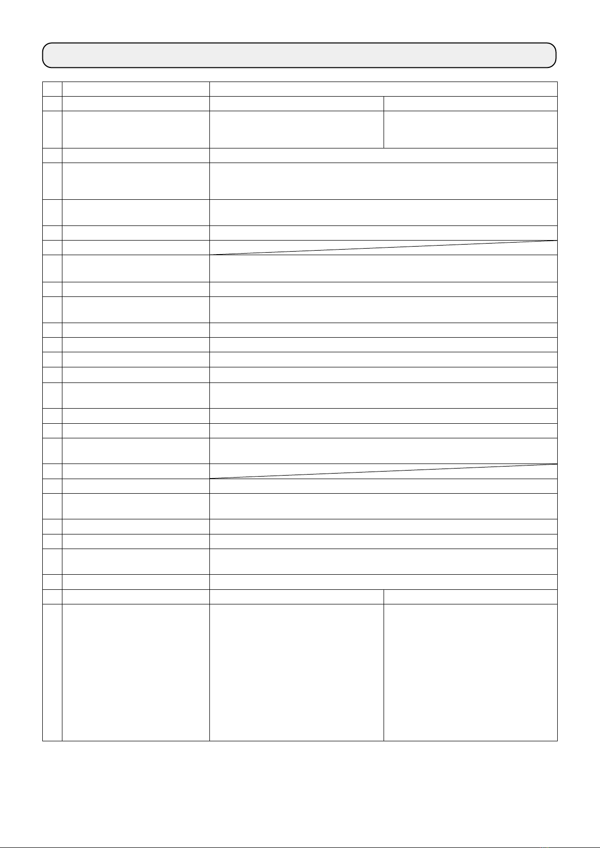
1 Model PLC-2710NM-7 PLC-2760NM-7
2 Model name 1-needle, post-bed, unison-feed,
lockstitch machine with vertical-axis
hook, with thread trimmer
2-needle, post-bed, unison-feed,
lockstitch machine with vertical-axis
hook, with thread trimmer
3 Application Medium- to heavy-weight materials, car seat, furniture
4 Sewing speed Max. 2,500 sti/min
(Refer to "6. SEWING SPEED TABLE"
in the Instruction Manual for the standard model.) *1
5 Needle GROTZ BECKERT 135 x 17 (Nm 100 to Nm 180) (Standard : Nm 140)
6 Applicable thread size for sewing # 30 to # 5 (Europe 60 / 3 to 20 / 3)
7 Applicable thread size to be cut # 30 to # 5 (Europe 60 / 3 to 20 / 3)
8 Stitch length Max. 12 mm (forward/reverse feed)
However, the machine is shipped with its stitch length restricted to 7 mm.
9 Stitch length dial 2-pitch dial
10 Presser foot lift Hand lifter : 10 mm
Automatic presser foot lifter : 20 mm
11 Stitch length adjusting
mechanism
By dial
12 Reverse stitch adjusting method Air cylinder type (with touch-back switch)
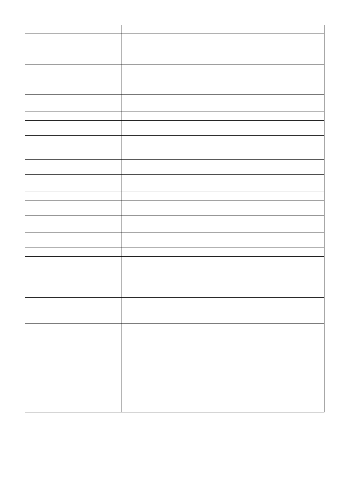
13 Thread take-up Link thread take-up
14 Needle bar stroke 40 mm
15 Amount of the alternate vertical
movement
1 mm to 9 mm (Alternate vertical dial adjustment type)
However, the machine is shipped with its stitch length restricted to 6.5 mm.
16 Hook Full-rotary vertical-axis 1.6-fold hook (Latch type)
17 Feed mechanism Box feed
18 Top and bottom feed actuation
mechanism
Main shaft direct drive system/Timing belt
19 Thread trimming method Cam-driven scissors type
20 Lubrication Automatic lubrication by semi-dry head plunger pump (with oil gauge)
21 Lubricating oil JUKI New Defrix Oil No. 1 (equivalent to ISO standard VG7)
or JUKI MACHINE OIL No. 7
22 Bed size 643 mm × 178 mm
23 Space under the arm 347 mm × 298 mm
24 Hand wheel size Outer diameter : ø123 mm
25 Motor/Control box 550W AC servomotor / SC-922B
26 Machine head weight 81 kg 84 kg
27 Rated power consumption 193VA
28 Noise -Equivalent continuous emission
sound pressure level (LpA) at the
workstation:
A-weighted value of 79.5 dB;
(Includes KpA = 2.5 dB); according to
ISO 10821- C.6.2 - ISO 11204 GR2
at 2,500 sti/min.
-Equivalent continuous emission
sound pressure level (LpA) at the
workstation:
A-weighted value of 84.0 dB;
(Includes KpA = 2.5 dB); according to
ISO 10821- C.6.2 - ISO 11204 GR2
at 2,500 sti/min.
-Sound power level (LWA);
A-weighted value of 86.0 dB;
(Includes KWA = 2.5 dB); according to
ISO 10821- C.6.2 - ISO 3744 GR2 at
2,500 sti/min.
*1 The speed setting according to the amount of the alternating vertical movement of the walking foot
and presser foot is automatically carried out.