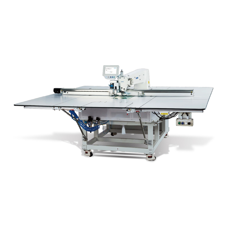
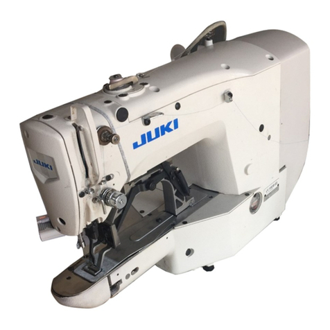
JUKI LBH-1790 Series User manual

LBH-1790
INSTRUCTION MANUAL
ENGLISH

i
CONTENTS
!.
IMPORTANT SAFETY INSTRUCTIONS........................................................................1
@.SPECIFICATIONS..........................................................................................................1
1. Subclass................................................................................................................................................1
2.Specications .......................................................................................................................................1
3.Standardsewingshapelist .................................................................................................................2
4.Conguration ........................................................................................................................................3
#. INSTALLATION ..............................................................................................................4
$. PREPARATION BEFORE OPERATION ......................................................................12
1.Lubrioation ..........................................................................................................................................12
2.Insertingtheneedle............................................................................................................................12
3.Threadingtheneedle-thread .............................................................................................................13
4.Threadingthebobbincase ................................................................................................................13
5.Adjustingthebobbinthreadtension ................................................................................................14
6.Installationofbobbincase ................................................................................................................14
7.Installingtheknife ..............................................................................................................................15
%. OPERATION OF THE SEWING MACHINE .................................................................16
1.Explanationoftheoperationpanelswitch.......................................................................................16
2.Basicoperationofthesewingmachine ...........................................................................................18
3.Howtousethepedal..........................................................................................................................18
4.Inputofthepressertype....................................................................................................................20
5.Performingpatternselection.............................................................................................................21
6.Changingneedlethreadtension .......................................................................................................22
7.Performingre-sewing.........................................................................................................................23
8.Windingbobbinthread.......................................................................................................................24
9.Usingthecounter ...............................................................................................................................25
10.Usingtheinitialvaluepattern............................................................................................................26
11.Changingsewingdata........................................................................................................................27
12.Methodofsettingsewingdatawith/withoutedit.............................................................................28
13.Sewingdatalist...................................................................................................................................29
14.Copyingsewingpattern .....................................................................................................................34
15.Usingpatternregisterkey .................................................................................................................35
16.Usingparameterregisterkey ............................................................................................................36
17.Performingcontinuousstitching ......................................................................................................37
18.Performingcyclestitching.................................................................................................................39
19.Explanationofpluralmotionsofknife .............................................................................................41
20.Methodofchangingmemoryswitchdata ........................................................................................42
21.Memoryswitchdatalist .....................................................................................................................43
^. MAINTENANCE ...........................................................................................................47
1.Adjustingtheneedle-to-hookrelation ..............................................................................................47
2.Adjustingtheneedlethreadtrimmer ................................................................................................48
3.Adjustingthepresserbarpressure ..................................................................................................49
4.Adjustmentofthebobbinpresserunit.............................................................................................49
5.Threadtension ....................................................................................................................................50
6.Cleaningthelter ...............................................................................................................................51
7.Replacingthefuse..............................................................................................................................51
&. GAUGE COMPONENTS..............................................................................................52
1.Clothcuttingknife ..............................................................................................................................52
2.Throatplate .........................................................................................................................................52
3.Presser.................................................................................................................................................52
*. ERROR CODE LIST.....................................................................................................53
(. TROUBLES AND CORRECTIVE MEASURES ...........................................................56
). DRAWING OF THE TABLE..........................................................................................58
_. INITIAL VALUE DATA FOR EACH SHAPE TABLE ....................................................59
– 1 –
!.
IMPORTANT SAFETY INSTRUCTIONS
@.SPECIFICATIONS
Computer-controlled, high-speed, lockstitch buttonholing machine, LBH-1790, has the subclass machines below.
2.Specications
1) Never operate the machine unless the oiling tank has been properly lubricated.
2) Be sure to remove any dust from the hook or bobbin thread cutting knife section at the end of the day,
and check the amount of oil remaining.
3) Be sure to return the activating pedal to the home position after the machine has started to run.
4) A safety switch is installed so that this sewing machine can not be operated in the state that the ma-
chine head is tilted. When operating this sewing machine, turn the power switch ON after setting the
sewing machine to the bed base properly.
1. Subclass
Sewing speed
Standard speed : 3,600 sti/min (Max. : 4,200 sti/min) (Max. : 3,300 sti/min when dry hook is used)
Needle DPX5 #11J to #14J
Hook DP type full-rotary hook
Needle rocking
drive method
Drive by stepping motor
Feed drive method Drive by stepping motor
Presser lifting
drive method
Drive by stepping motor
Lift of presser foot 14 mm (Optional setting available) Max. : 17 mm (At the time of needle up by reverse run)
Cloth cutting knife
drive method
By double-acting solenoid drive
Standard sewing
shape
30 kinds
Number of pat-
terns stored in
memory
99 patterns
Motor used Single phase 220/230/240 V, 3-phase 200 to 240 V, 1000 VA
Noise
- Equivalent continuous emission sound pressure level (LpA) at the workstation :
A-weighted value of 80.0 dB ; (Includes ; KpA = 2.5 dB) ; according to ISO 10821- C.6.3 -ISO
11204 GR2 at 3,600 sti/min.
Subclass
Major applica-
tion
Buttonholing
size
LBH-1790S
Buttonholing of
cloth such as men’
s shirts, blouses,
work uniforms,
ladies' wear, etc.
Standard:Max.5mm
Specialtypepart:Max.10mm
Buttonholingsewinglength
Standard:Max.41mm
LBH-1795S:Max.120mm
Knifesizeused:
6.4to31.8mm(1/4'to1-1/4')
LBH-1792K
Buttonholing of
knits such as knit-
ted underwear,
sweaters, cardi-
gans, jersey, etc.
LBH-1795S
Buttonholing of
cloth such as men’
s shirts, blouses,
work uniforms,
ladies' wear, etc.
Holing of child-car
seat belts

– 2 –
3.Standardsewingshapelist
(1) Square type (2) Round type (3) Radial square type (4) Radial type (5) Radial straight bar-
tacking type
(6) Radial taper bar-
tacking type
(7) Eyelet square type (8) Eyelet radial type (9) Eyelet straight bar-
tacking type
(10) Eyelet taper bar-
tacking type (11) Semilunar type (12) Round square type
(13) Semilunar square
type
(14) Semilunar straight
bar-tacking type
(15) Semilunar taper
bar-tacking type
(16) Eyelet semilunar
type (17) Eyelet round type (18) Square radial type
(19) Square semilunar
type (20) Square round type (21) Square straight
bar-tacking type
(22) Square taper bar-
tacking type
(23) Radial semilunar
type (24) Radial round type
(25) Semilunar radial
type
(26) Semilunar round
type (27) Bar-tacking (28) Bar-tacking, right
cut (29) Bar-tacking, left cut (30) Bar-tacking, center
cut
PANEL
DISPLAY
PANEL
DISPLAY
PANEL
DISPLAY
PANEL
DISPLAY
PANEL
DISPLAY
PANEL
DISPLAY
PANEL
DISPLAY
PANEL
DISPLAY
PANEL
DISPLAY
PANEL
DISPLAY
PANEL
DISPLAY
PANEL
DISPLAY
PANEL
DISPLAY
PANEL
DISPLAY
PANEL
DISPLAY
PANEL
DISPLAY
PANEL
DISPLAY
PANEL
DISPLAY
PANEL
DISPLAY
PANEL
DISPLAY
PANEL
DISPLAY
PANEL
DISPLAY
PANEL
DISPLAY
PANEL
DISPLAY
PANEL
DISPLAY
PANEL
DISPLAY
PANEL
DISPLAY
PANEL
DISPLAY
PANEL
DISPLAY
PANEL
DISPLAY

– 3 –
4.Conguration
LBH-1790 consists of the following components.
1
2
5
4
3
6
7
1Power ON/OFF switch
2Machine head (LBH-1790)
3Operation panel
4Control box (MC-601)
5Presser lifting pedal
6Starting pedal
7Thread stand device

– 4 –
(1)Set-upofthetable
#. INSTALLATION
WARNING:
To prevent possible accidents caused by the fall of the sewing machine, perform the work by two
personsormorewhenthemachineismoved.
1) Securely install control box 2and power switch 3on table 1.
2) Securelyxtherespectivepowercablesofpowerswitch3.
3) Passfourbedbasexedscrews!1 through bed base 4.
4) Set rubber cushions 5to holes 6(4places)forxingbedbaseandxbedbase4.
5) Fix head support bar 7on table 1.
6) After placing the sewing machine main unit on bed base 4, connect pedal (right side) to pedal switch
9, and pedal (left side) to pedal sensor !0 respectively with connecting rods 8which have been
supplied as accessories.
Adjustthepositionsofthepedalssothatconnectingrods8andcontrolbox2donot
comeincontactwitheachother.
1
2
5
4
3
6
7
8
!0
!1
9

– 5 –
(2)Connectingthepowersourcecord
•Voltagespecications
Powersourcespecicationsareindicatedonthe
voltage indication seal. (3-phase type only)
Forothertypemachines,powersourcespecica-
tions are indicated on the voltage caution seal and
the rating label.
Connectthecordinaccordancewiththespecica-
tions.
Table
Brown Brown
Brown
Lightblue Lightblue
Light
blue
Green/Yellow Green/
Yellow
Controlbox
Green/Yellow
Plug
Powersourcecord
Powerswitch
GND
AC200 V
AC220 V
AC230 V
AC240 V
Voltageindicationseal(3-phasetypeonly)
•Connectingsinglephase200V,220V,230Vand240V
Table
Red
Black
Green/
Yellow
White
Controlbox
Powersourcecord
Plug
Powerswitch
GND
AC200 V
AC220 V
AC240 V
•Connectingthreephase200V,220Vand240V
Green/Yellow
Voltagecautionseal
Red
White
Black
Green/
Yellow
Red
Black
White
Ratinglabel
1. Neveruseunderthewrongvoltageandphase.
2.When changingthevoltage, refertothe itemof"Changing thevoltageof 100/
200V".

– 6 –
(3)Changingthevoltageof100/200V
WARNING:
Topreventpersonalinjuriescausedbyelectricshockhazardsorabruptstartofthesewing
machine,carryouttheworkafterturningOFFthepowerswitchandalapseof5minutesor
more.Topreventaccidentscausedbyunaccustomedworkorelectricshock,requestthe
electricexpertorengineerofourdealerswhenadjustingtheelectricalcomponents.
Changing procedure of the changeover connector
1. Turn OFF the power source with the power
switchafterconrmingthatthesewingmachine
has stopped.
2. Draw out the power cord from the power plug
socketafterconrmingthatthepowerswitchis
turnedOFF.Thenwaitforveminutesormore.
3. Remove the front cover.
4.Removefourscrewsxingtherearcoverofthe
control box and slowly open the rear cover.
A.Incaseofusingwith3-phase200Vto240V
• Changing the changeover connector
Connect to 200V the 100/200V changeover con-
nector of FLT p.c.b. 1located on the side of the
Box Side of the control box.
• Connect the crimp style terminal of AC input cord
tothepowerplugasshowninthegure.
B.
Incaseofusingwithsinglephase100Vto120V
• Changing the changeover connector
Connect to 100V the 100/200V changeover
connector of FLT p.c.b. 1located on the side of
the Box Side of the control box.
• Connect the crimp style terminal of AC input cord
tothepowerplugasshowninthegure.
(Caution)
Securelyperformtheinsulationtreat-
menttotheredterminalwhichisnot
usedwithinsulationtapeorthelike.
(Whentheinsulationisinsufcient,
thereisadangerofelectricshockor
leakagecurrent.)
C.
Incaseofusingwithsinglephase200Vto240V
• Changing the changeover connector
Connect to 200V the 100/200V changeover con-
nector of FLT p.c.b. 1located on the side of the
Box Side of the control box.
• Connect the crimp style terminal of AC input cord
tothepowerplugasshowninthegure.
(Caution)
Securelyperformtheinsulationtreat-
menttotheredterminalwhichisnot
usedwithinsulationtapeorthelike.
(Whentheinsulationisinsufcient,
thereisadangerofelectricshockor
leakagecurrent.)
5. Check that the change has been performed with-
out fail before closing the rear cover.
6. Be careful that the cord is not pinched between
the rear cover and the control box main unit.
Close the rear cover while pressing the lower
side of rear cover, and tighten four screws.
It is adaptable to the voltage of single phase 100V to 120V/3-phase 200V to 240V by changing the
voltage changeover connector mounted on FLT p.c.b.
(Caution) When the changing procedure is wrong, the control box will be broken. So, be
verycareful.
1
GREEN/
YELLOW
(Plugside)
WHITE
BLACK
RED
WHITE
BLACK
RED
GREEN/
YELLOW
GREEN/
YELLOW
(Plugside)
WHITE
BLACK
RED
WHITE
BLACK
RED
GREEN/
YELLOW
(Plugside)
GREEN/
YELLOW
GREEN/
YELLOW
A
B
C
WHITE
BLACK
RED
WHITE
BLACK
RED

– 7 –
(4)Installingthesewingmachinemainunit
1) Place hinge plates 1and shaft bearings 2-1
(rubber) and 2-2 (metal) in two places on the
headbaseandxthehingeplatestothema-
chine head with setscrews 3in two places.
Whentherubberhingeandmetaltting
hingeareinstalledinreverseorder,it
isdangeroussincethesewingmachine
shakeswhenitistilted.So,becareful.
WARNING:
Topreventpossibleaccidentscausedby
thefallofthesewingmachine,performthe
workbytwopersonsormorewhenthe
machineismoved.
2-1(rubber)
2-2
(metal)
(5)Tiltingthesewingmachinehead
When tilting the sewing machine head, tilt quietly
the sewing machine until head support bar 1
comes in contact with it.
1.
Makesurethatsewingmachinehead
supportbar
1
isplacedonthetable
beforetiltingthesewingmachine.
2. Toprotectfall-down,besuretotilt
thesewingmachineinalevelplace.
WARNING:
Whentilting/raisingthesewingmachinehead,performtheworksoasnottoallowyourngers
tobecaughtinthemachine.Inaddition,toavoidpossibleaccidentscausedbyabruptstartof
themachine,turnOFFthepowertothemachinebeforestartingthework.
1
3
1

– 8 –
(6)Connectingthesafetyswitchconnector
1) Connect safety switch connector
1with connector 2located on the
machine head side.
(7)Installingthehookoilshieldplate
Install hook oil shield plate 1onto bed base 3with
setscrew 2.
Fixthesewingmachinesothatit
doesnotcomeincontactwithhook
oilshieldplate1whenraising/tilting
thesewingmachine.
(8)Installingtheoperationpanel
Fix operation panel attaching plate 1on the table
with woodscrew 2and pass the cable through hole
3in the table.
Cordclamp
1
2
1
2
3
1
2
3

– 9 –
1
(9)Connectingthecords
Performtheconnectionofthecordsasshowninthegurebelow.
Electricbobbinwindingdevice(optional)
1) Pass 4 cords (CN38, 39, 41, and 42) connect-
ing to the right side among the cords connecting
to MAIN circuit board through cord clamp A as
showninthegure,andconnectthemtothere-
spective connectors. Connect CN37 to the con-
nector without passing through cord clamp A.
In addition, when using the electric bobbin wind-
ing device (optional), similarly pass the cord
of the bobbin winding device through the cord
clamp and connect it to CN44.
2) Directly connect the cord from the operation
panel connecting to the left side of MAIN circuit
board to CN34.
3) Connect the cords connecting to SDC circuit
board directly to CN14 and CN16.
4) Fix the earth wire with the setscrew 1.
MAINcircuit
board
Sewingmachinehead
Operationpanel
CN44
CN34
CN41
CN39
CN42
CN38
CN37
CN16
CN14
CN44
CN34
CN41
CN39
CN42
CN38
CN37
CN16 CN14
Cord
clampA
CN16
CN14
SDCcircuit
board
SDCcircuitboard

– 10 –
(11)Installingtheeyeprotectioncover
Be sure to install and use eye protection cover 1and use the sewing machine.
WARNING:
Besuretoattachthiscovertoprotecttheeyesfromthedisperseofneedlebreakage.
Whenplacedlongitudinally Whenplacedhorizontally
(10)Managingthecord
1) Slowly tilting the sewing machine, check that the cords are not forcibly pulled.
2) Fix the cords with cord setting plate 1asshowninthegure.
Whenyoutiltthesewingmachine,makesurethatthesewingmachineheadsupport
bar2isplacedonthetable.
Operator
Operator
1
2
1
1

– 11 –
(12)Fixingthetemporarystopswitch
ThetemporarystopswitchhasbeeninthestateasshowningureAatthetimeofdelivery.
Loosen setscrew 1andsettheswitchinthestateasshowningureB,andxitwithsetscrew1to-
gether with setscrew 2supplied with the machine.
(13)Threadguiderod
Securelytthethreadguiderodsothattwoside
holes in the thread guide rod face the thread guide.
Threadguiderod
(14)Installingthethreadstand
1) Assemble the thread stand, and set it in the
hole in the top right corner of the machine table.
2) Tighten locknut 1toxthethreadstand.
3) When ceiling wiring is possible, pass the power
cable through spool rest rod 2.
A
B
➡
11
2
1
2

– 12 –
$. PREPARATION BEFORE OPERATION
Hold needle with its recessed part facing toward the operator side
A, insert the needle fully into the needle clamping hole, and tighten
needle setscrew 1. Use a DPx5-(#11J, #14J).
Whenattachingtheneedle,turnOFFthe powertothe
motor.
2.Insertingtheneedle
WARNING:
To protect againstpossible personalinjury dueto abrupt start of themachine, besure tostart the
followingworkafterturningthepoweroffandascertainingthatthemotorisatrest.
1)Lubricatingoiltooilingtank
™Fill the oiling tank with New Defrix Oil No.1 up to the level indicated by “MAX” 1.
2)Adjustingthelubricationforthesewinghook
™Adjust the amount of oil supplied to the sewing hook by loosening lock nut 2and turning oil amount
adjusting screw 3.
™Amount of supplied oil is reduced when turning the screws 3clockwise.
™Fix the screw with lock nut 2after adjusting the lubrication for the sewing hook.
™When you first operate your sewing machine after set-up or after an extended period of disuse,
remove the bobbin case and apply a few drops of oil to the hook race. In addition, apply a few drops
oil from oiling hole 5in hook driving shaft front metal 4to soak the inside felt in oil.
WARNING:
To protect againstpossible personalinjury dueto abrupt start of themachine, besure tostart the
followingworkafterturningthepoweroffandascertainingthatthemotorisatrest.
Detaileddiagramofoilamountadjustingsection
Oil pipe
Decrease
Oilamount
Increase
1.Lubrioation
1
5
4
23
2
3
A
1

– 13 –
Rotatingdirectionofbobbinandthreading
1) Fit the bobbin so that it rotates in the direction of the arrow.
2) Pass the thread through thread slit 1, then through under the tension spring 2, again through thread
slit 3, and pull the thread from 4.
3) Threading at 4for purl stitching is different from that for whip stitching. So, be careful.
4.Threadingthebobbincase
3.Threadingtheneedle-thread
Pass the needle thread in the order 1to !2asshowninthegures.
The threading can be done easily by using the needle threader supplied with the machine.
Change the thread guide threading method according to the thread to be used.
Syntheticlamentthread
Cottonthread,spunthread
WhipstitchPurlstitch
Bobbincase
Bobbin
WARNING:
To protect againstpossible personalinjury dueto abrupt start of themachine, besure tostart the
followingworkafterturningthepoweroffandascertainingthatthemotorisatrest.
1
2
5
4
3
6
7
8
9
!0
!1
!2
1
2
3
4
4

– 14 –
5.Adjustingthebobbinthreadtension
6.Installationofbobbincase
1) Lift up and hold bobbin case latch lever between
twongers.
2) Push the bobbin case into the hook so that it is
supported by the hook shaft 1and then snap in
the latch lever.
Press the bobbin case until the predetermined
position is reached, and it will click.
1. Ifthebobbincaseisoutofthe
predeterminedposition,itcanjump
outfromthehooktocausethe
needlethreadtotangleonthehook
shaft.Checktobesurethatthe
bobbincaseisproperlyinstalledin
thecorrectposition.
2. Thereisadifferenceintheshapeof
bobbincasebetweenthestandard
hookandthedryone.Theyhave
nothingincommonwitheachother.
Adjust the bobbin thread tension as given below when the bobbin thread is pulled up at the position where
thread slit 1of bobbin case comes up.
Purl stitch
Whip stitch
0.05 to 0.15N
0.15 to 0.3N
To such an extent that bobbin case quietly comes down when
holding thread end coming from bobbin case and shaking it quietly
up and down.
To such an extent that bobbin case barely comes down when
holding thread end coming from bobbin case and shaking it
somewhat strongly.
WARNING:
To protect againstpossible personalinjury dueto abrupt start of themachine, besure tostart the
followingworkafterturningthepoweroffandascertainingthatthemotorisatrest.
1
2
1
Turning tension adjust screw 2clockwise will increase bobbin thread tension, and turning it
counterclockwise will decrease the tension.
Adjustthebobbinthreadtensiontolowerforsyntheticlamentthread,andtohigherforspunthread.
The thread tension is higher by approximately 0.05N when the bobbin case is set to the hook since idle-
prevention spring is provided.
Whenbobbinthreadtensionisadjusted,checktheneedlethreadtensionsettingof
thememoryswitch.(SeeP.44.)

– 15 –
7.Installingtheknife
Inch→mmCONVERSIONTABLE
When the cloth cutting knife you have is indicated in
inch, set the cloth cutting length (knife size) in mm
using the inch →mm conversion table. (See P.29.)
When replacing the knife with a new one, perform as
follows.
1) Knife 1can be easily removed together with the
washer when removing knife retaining screw 2.
2) Adjust so that the knife, when lowered the knife
bar by hand, is spaced 1 to 2 mm away from the
top surface of the throat plate as illustrated in the
sketch. Then, be sure to place the washer and
tighten the knife retaining screw.
1to2mm
WARNING:
To protect againstpossible personalinjury dueto abrupt start of themachine, besure tostart the
followingworkafterturningthepoweroffandascertainingthatthemotorisatrest.
1
2
Knife size Indication of mm
1/4 6.40
3/8 9.50
7/16 11.10
1/2 12.70
9/16 14.30
5/8 15.90
11/16 17.50
3/4 19.10
13/16 20.60
7/8 22.20
1 25.40
1 1/8 28.60
1 1/4 31.80
1 3/8 34.90
1 1/2 38.10

– 16 –
%. OPERATION OF THE SEWING MACHINE
Thereare3statesbelowaccordingtoback-lightcolors.
Blue:Inputmode .......... Datachangeispossible.
Green:Sewingmode .... Sewingpossiblestate
Yellow:Errorstate ........ Someerroroccurs.
1
2 543 6
7
8
9
!0
!1
!2
!5
!6
!7
!3
!4
!8
!9
@0
@1
@2
@3
@4 @5 @6
@7
@8
@9
#0
1.Explanationoftheoperationpanelswitch

– 17 –
No.
1
2
3
4
5
6
7
8
9
!0
!1
!2
!3
!4
!5
NAME
LCD display
READY key
RESET key
MODE key
PRESSER key
WINDER key
PATTERN NO. key
DATA key
COUNTER key
ITEM SELECTION
key
DATA CHANGE
key
SHAPE key
THREAD TENSION AT
PARALLEL SECTION key
THREAD TENSION AT
BAR-TACKING SECTION
key
PITCH key
FUNCTION
Various data such as pattern No.,
shape, etc. are displayed.
Press this key when starting sewing.
Every time this key is pressed,
change-over of sewing ready set state
and data set state can be performed.
Press this key when releasing error,
travelling the feed mechanism to its
initial position, counter resetting, etc.
Press this key when changing data of
the memory switches.
This key lifts or lowers the presser. When
the presser goes up, the needle bar
travels to the origin and when it comes
down, the needle bar travels to the right.
This key is pressed when performing
bobbin winding.
This key selects pattern No. display.
This key selects data display.
Thus key selects counter display.
This key selects pattern No., data
No., etc.
This key changes various data.
This key selects shape display.
This key selects thread tension at
parallel section display.
This key selects thread tension at
bar-tacking section display.
This key selects pitch of parallel
section.
No.
!6
!7
!8
!9
@0
@1
@2
@3
@4
@5
@6
@7
@8
@9
#0
NAME
OVEREDGING
WIDTH key
BAR-TACKING
WIDTH, LEFT key
BAR-TACKING
WIDTH, RIGHT
key
CLOTH CUT
LENGTH key
CLEARANCE key
KNIFE GROOVE
WIDTH, RIGHT
key
KNIFE GROOVE
WIDTH, LEFT key
COPY key
PRESSER
SELECTION key
FORWARD key
BACKWARD key
PATTERN
REGISTRATION key
PARAMETER
REGISTRATION key
Speed variable
resister
LCDadjustment
variable rsistor
FUNCTION
This key selects overedging width
display.
This key selects left side of bar-
tacking width compensation display.
This key selects right side of bar-
tacking width compensation display.
This key selects cloth cut length display.
This key selects clearance display.
This key selects knife groove width,
right compensation display.
This key selects knife groove width,
left compensation display.
Press this key when copying pattern.
This key selects presser type.
This key makes the feed mechanism
travel forward stitch by stitch.
This key makes the feed mechanism
travel backward stitch by stitch.
This is a short cut key that pattern registration
is available. Registration of shortcut to setting
display of an optional pattern is possible. For
the setting procedure, see P.36.
This is a short cut key that parameter
registration is available. Registration of shortcut
to setting display of an optional pattern, sewing
parameter or adjustment data is possible. For
the setting procedure, see P.37.
Speed increases when this is lifted
upward and decreases when this is
lowered downward.
Light and shade of LCD display can
be adjusted.

– 18 –
1)TurnONthepowerswitch.
First, check that presser type A which has been
set is the same as that of the presser actually
mounted. For checking and setting procedures,
refer to 4.Inputtingthepressertype.
2)SelectthepatternNo.youdesiretosew.
When the power is turned ON, the pattern No.
Bwhichisselectedatpresentashesonand
off. When you desire to change it, press ITEM
SELECTION key !0 and select the No.
you desire to sew. When you purchase the
sewing machine, pattern No. 1 to 10 described in
11.Changingsewingdata have been registered.
Select the pattern No. you sesire to sew from
among these numbers. (The No. with which the
pattern has not been registered is not displayed.)
3)Setthesewingmachinetosewingpossiblestate.
Press READY key 2and the back-light of LCD display 1changes from blue color to green color,
and sewing is possible.
4)Startsewing.
Set the sewing product to the presser portion, and operate the pedal to start the sewing machine, and
sewing starts. When you purchase the sewing machine, 2-pedal type has been set. However, pedal
operating procedure can be selected from among three ones. Select the operating procedure you desire
and use the sewing machine. →3.Howtousethepedal
This sewing machine can be used by selecting the pedal operating procedure from among 3 types below.
Selecttheoperatingprocedureyoudesireforworkingefciencyandusethesewingmachine.
(1)Settingprocedureofthepedaltype
1)Callthepedaltypesettingparameter.
Press MODE key 1for as long as three
seconds in the state of the input mode and
memory switch (level 2) edit screen A is
displayed. When the pedal type selection
parameter is not displayed, press ITEM
SELECTION key !0 to select the pedal
type.
2)Selectthepedaltype
Press DATA CHANGE key !1 and the
picture is changed as shown in the illustration
below. Select the pedal type B you desire.
2
!0
BA
2-pedal 1-pedal
(Withoutintermediateposition)
1
1-pedal
(Withintermediateposition)
!0 !1
A
B
4
2.Basicoperationofthesewingmachine
3.Howtousethepedal
Other manuals for LBH-1790 Series
5
Table of contents
Other JUKI Sewing Machine manuals

JUKI
JUKI IP-110 Type F User manual

JUKI
JUKI LU-1510 User manual

JUKI
JUKI MB-1800 series User manual

JUKI
JUKI MO-1000 User manual

JUKI
JUKI LK-1910 Quick start guide

JUKI
JUKI HZL-30Z User manual

JUKI
JUKI DP-2100 User manual

JUKI
JUKI LZ-2290C/X73257 User manual

JUKI
JUKI PLK-J4040 User manual

JUKI
JUKI MF-7900 Series User manual
Popular Sewing Machine manuals by other brands

ELNA
ELNA Star Edition Service manual

Brother
Brother S-1110A instruction manual

Atlanta Attachment Company
Atlanta Attachment Company 1315A Technical Manual & Parts Lists

Husqvarna Viking
Husqvarna Viking Jade 20 user guide

Husqvarna Viking
Husqvarna Viking Designer Ruby Deluxe user guide

Consew
Consew 99 operating instructions