From the library of Superior Sewing Machine & Supply LLC • www.supsew.com
PREFACE:
This
operator's
manual has been prepared
to
guide
you
while
operating
the
MFC-7000 Series machines.
This
manual explains in detail
the
proper
settings
for
operation
of
the
machine.
Illustrations
are used
to
show
the
adjustments
and reference letters are used
to
point
out
specific
items
discussed.
Careful attention
to
the
instructions
and
cautions
for
operating and
adjusting
these
machines
will
enable you
to
maintain
the
superior
performance and reliability
designed
and
built
into
every
Union
Special machine.
Adjustments
andcautionsare presentedin
sequence
so
that
alogical
progression
is
accomplished.
Some
adjustments
performed
out
of
sequence may have an adverse
effect
on
the
function
of
the
other
related parts.
This
manual has been
comprised
on
the
basis
of
available
information.
Changes
in
design
and/or
improvements
may
incorporate
a
slight
modification
of
configuration
in
illustrations
or
cautions.
On
the
following
pages
will
be
found
illustrations
and
terminology
used
in
describing
operating
instructions
for
your
machine.
CONTENTS
PREFACE:
.................................................................................................................................................................2
SAFETY
RULES
..........................................................................................................................................................3
SPECIFICATIONS:
....................................................................................................................................................4
MOTOR
PULLEY
AND
V
BELT:
..................................................................................................................................4
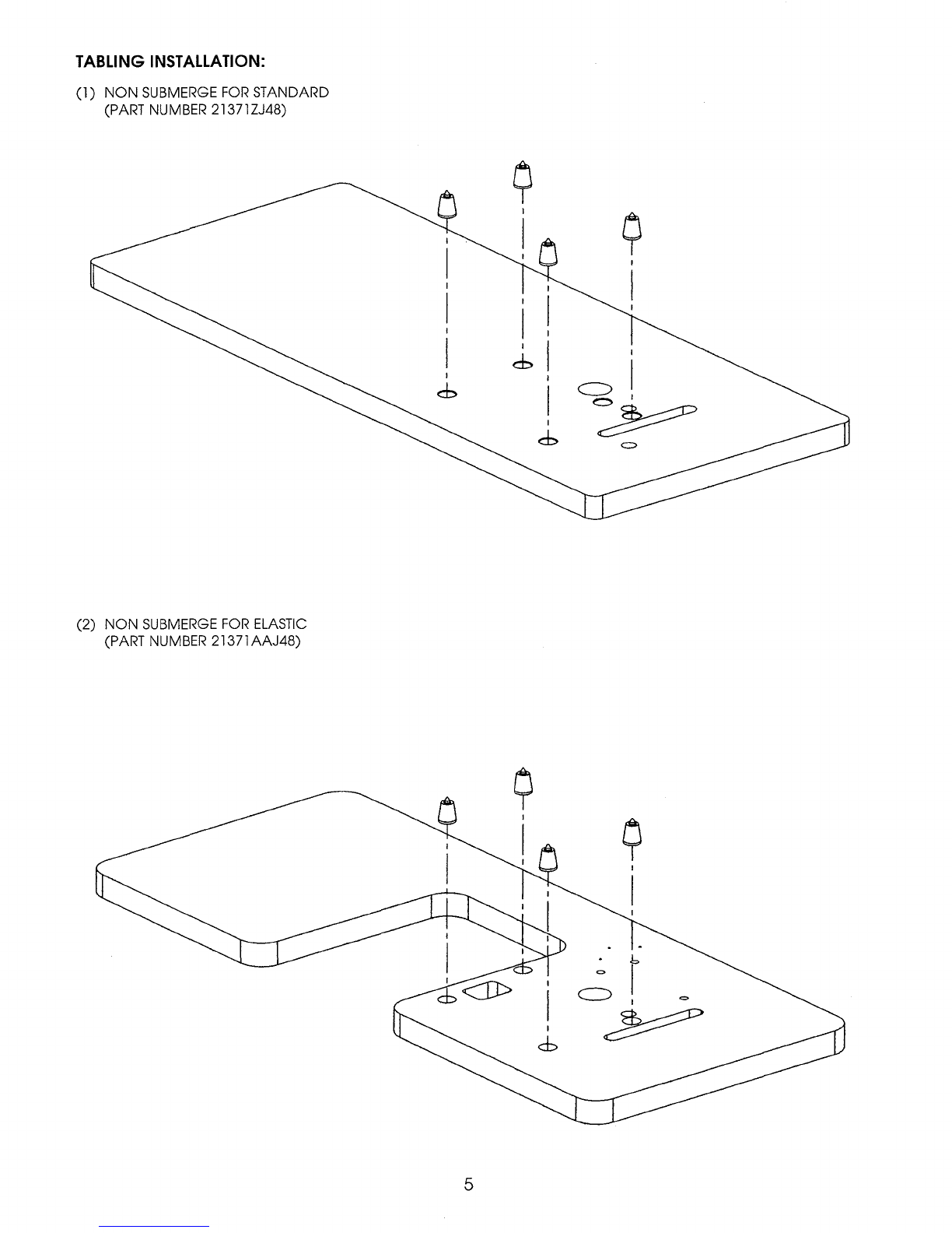
TABLING
INSTALLATION:
...................................
.-
..................................................................................................... 5
CAUTION
AREAS:
...................................................................................................................................................6
OPERATOR'S
DAILY
CHECK
UST:
.................................................................•........................................................... 7
ROTATION:
..............................................................................................................................................................7
OPERATING
CAUTIONS:
.........................................................................................................................................7
OPERATING
CAUTIONS
(CONT.): ..........................................................................................................................8
OPERATING
THE
PEDALS:
.........................................................................................................................................8
LUBRICATION:
.........................................................................................................................................................9
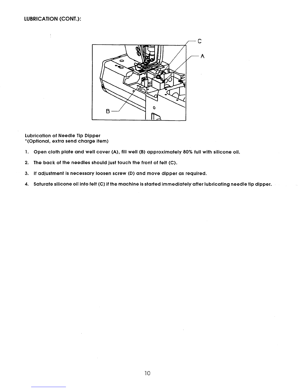
LUBRICATION
(CONT.):
........................................................................................................................................
10
INSERTING
NEEDLES:
.............................................................................................................................................
11
THREADING
THE
MACHINE:
.................................................................................................................................
12
THREADING
THE
MACHINE
(CONT.): ...................................................................................................................
13
DIFFERENTIAL
FEED
MECHANISM:
........................................................................................................................
14
ADJUSTING
THE
STITCH
LENGTH:
.........................................................................................................................
14
PRESSER
FOOT
PRESSURE
AND
LIFTER:
.................................................................................................................
15
ROLLER
PRESSURE
ADJUSTING
KNOB:
.................................................................................................................
15
PULLER
LIFTER
LEVER:
............................................................................................................................................
16
PULLER
STIITCH
LENGTH:
.......................................................................................................................................
17
ADJUSTMENT
OF
LOOPER
GAUGE:
......................................................................................................................
18
ADJUSTMENT
OF
NEEDLE
BAR
HEIGHT:
................................................................................................................
18
ADJUSTMENT
OF
LOOPER
AND
NEEDLE:
.............................................................................................................
19
ADJUSTMENT
OF
NEEDLE
GUARD:
.......................................................................................................................
19
ADJUSTMENT
OF
SPREADER:
................................................................................................................................
20
ADJUSTING
TAKE-UP
CAM: ..................................................................................................................................
21
ADJUSTMENT
OF
THREAD
GUIDE:
........................................................................................................................
22
MAINTENANCE:
....................................................................................................................................................
23
2