JUKI MO-104D User manual

SERVICE MANUAL
MO-114D/104D
2-Needle, 4-Thread Overlock Sewing Machine
MO-114D
MO-104D

Be sure to observe the following to protect against a re, electrical shock, injury or damaged components.
* Be sure to unplug the machine before disassembly, assembly or adjustment of the machine.
* Be sure to use the proper genuine parts when changing any of the machine parts.
CAUTION:
CONTENTS
1. Specications ..................................................................................................1
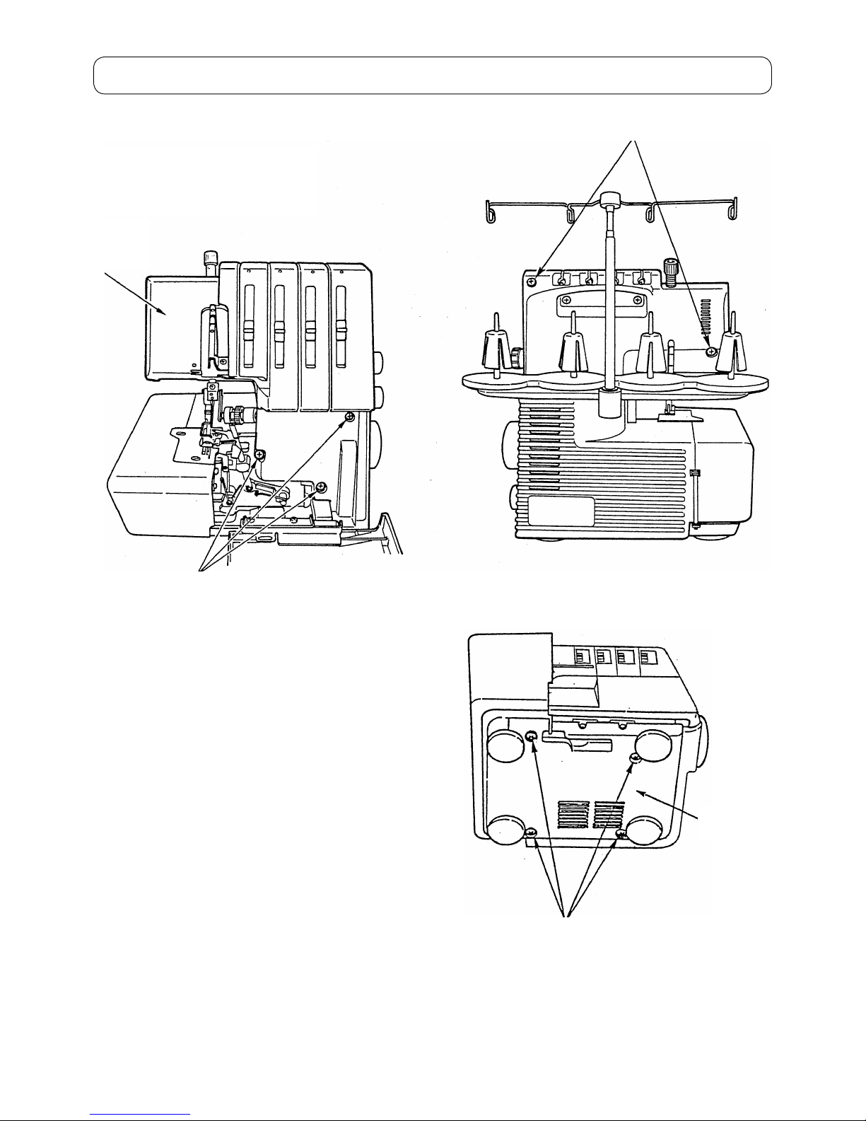
2. Removing order of covers ..............................................................................2
2-1. Front cover ...................................................................................................................2
2-2. Base plate .....................................................................................................................2
2-3. Rear cover ....................................................................................................................3
2-4. Cloth plate ....................................................................................................................3
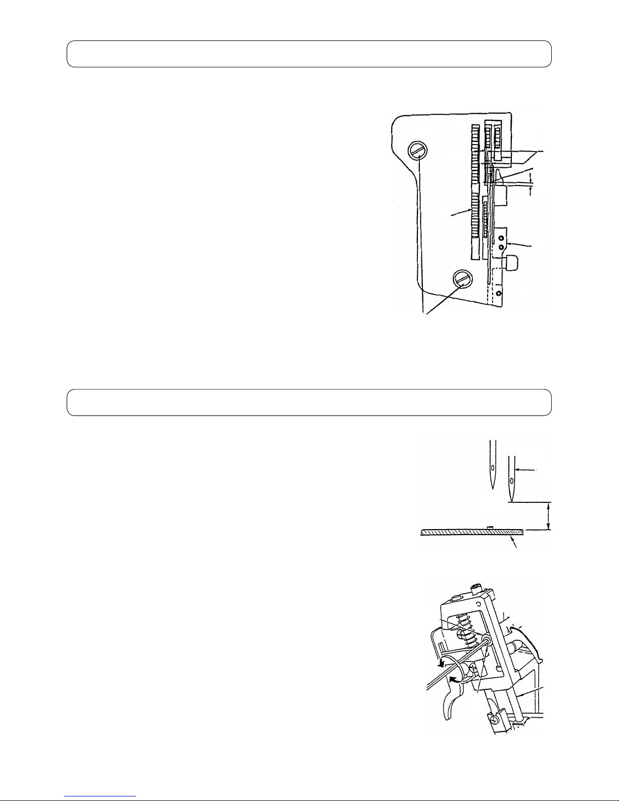
3. Installation of throat plate ..............................................................................4
4. Height of needle bar ........................................................................................4
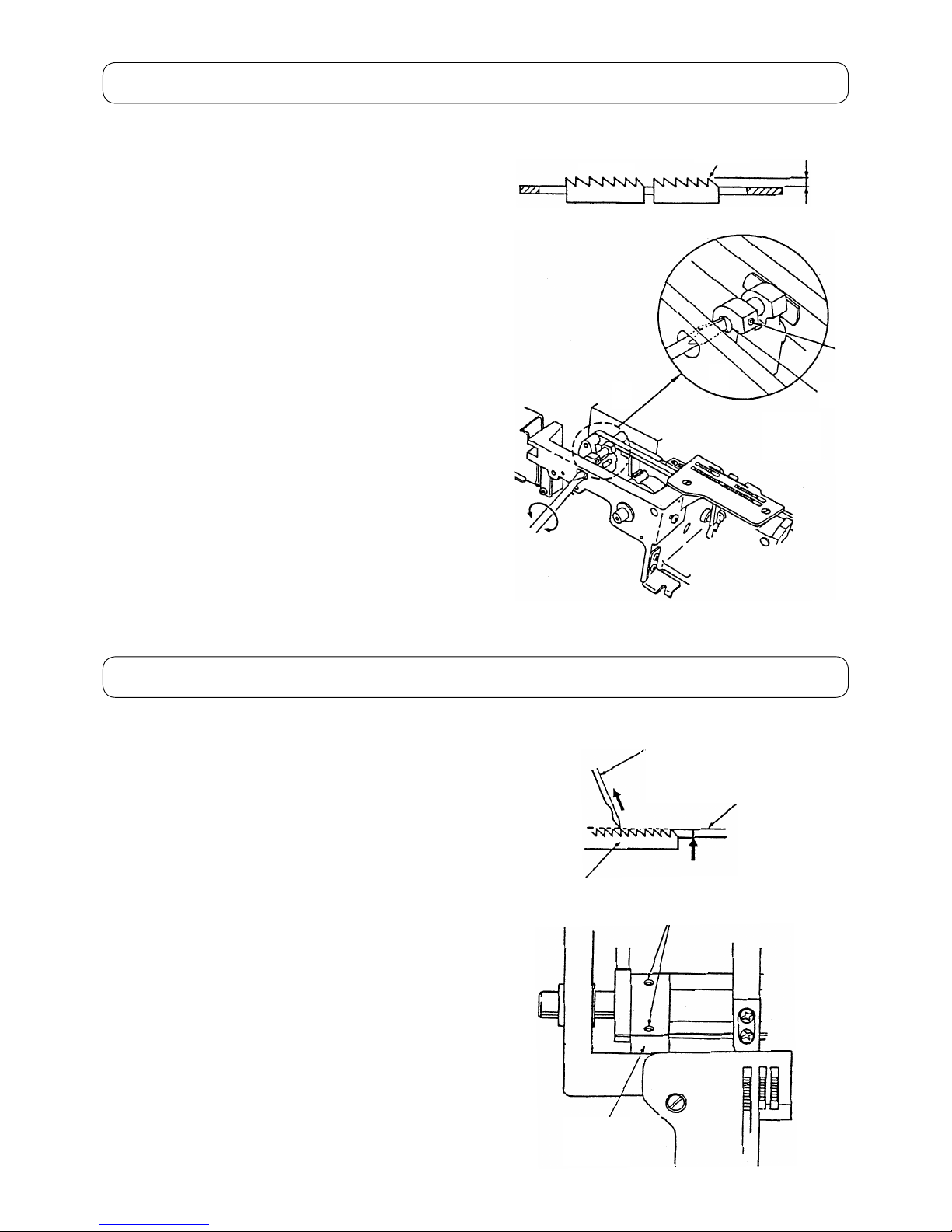
5. Position of feed dog ........................................................................................5
6. Adjusting stroke of main feed dog ................................................................6
7. Adjusting stroke of sub feed dog (MO-114D) ................................................7
8. Height of feed dog ...........................................................................................8
9. Feed dog timing ...............................................................................................8
10. Position of balance weights and cams..........................................................9
11. Projecting amount of upper looper ................................................................9
12. Radius of lower looper ..................................................................................10
13. Adjusting lower looper thread guide lever ..................................................10
14. Adjusting loop lift ..........................................................................................11
15. Timing between upper and lower looper .....................................................12
16. Installation of needle guards ........................................................................13
17. Position of upper looper thread take-up .....................................................13
18. Height and lateral position of presser foot .................................................14
19. Adjusting oating amount of thread tension disk ......................................15
20. Thread tension controller .............................................................................16
21. Position of needle thread take-up ................................................................17
22. Belt tension ....................................................................................................18
23. Position of lower knife ..................................................................................18
24. Engagement of upper knife with lower knife ..............................................19
25. Position of cloth plate ...................................................................................20
26. Adjusting presser foot pressure ..................................................................20

– 1 –
1. Specications
No. Items Description
1 Number of needle and threads 2-needle and 4-thread (with differential feed)
2 Needle 130/705H No. 70/80 (10/12)
3 Overedge width 2-needle, 4-thread : 6 mm
1-needle, 3-thread : 4 mm
Roll hemming : 2 mm
4 Stitch length 1.0 to 4.0 mm (standard : 2.5 mm)
5 Differential feed ratio 1 : 0.5 to 0.7 (standard : 1.2 ± 0.3)
6 Needle bar stroke 27 mm
7 Feed dog height 1.3 mm (standard)
8 Presser foot height 5 mm (standard), 7 mm (two step presser foot)
9 Power consumption 105 W
10 Motor (built-in) Input : 90 W, Output : 42 W (120 V)
Input : 90 W, Output : 44 W (240 V)
11 Light 15 W screw type (120 V)
10 W screw type (240 V)
12 Power switch 2-step rocker switch
13 Sewing speed Max. 1,500 sti/min (SPM)
14 Driving system Timing belt. Machine rotates in the forward (normal) direction
15 Machine size 315 (W) × 290 (D) × 290 (H)
16 Machine weight 7.0 kg
17 Foot control Electronic type

– 2 –
2. Removing order of covers
3
B
2
1
A
2-1. Front cover
○ Remove the setscrews 1(3 locations).
○ Remove the setscrews 2(2 locations).
○ Remove the front cover A.
2-2. Base plate
○ Remove the setscrews 3(4 locations).
○ Remove the base plate B.

– 3 –
6
54
D
C
2-3. Rear cover
○ Remove the setscrews 4(2 locations).
○ Remove the presser foot adjusting screw 5.
○ Raise the presser foot lifting lever 6.
○ Open the cloth plate D.
○ Remove the rear cover C.
7
D
D
<MO-114D>
<MO-104D>
2-4. Cloth plate
○ Remove the setscrews 7(2 locations).
○ Remove the cloth plate D.

– 4 –
3. Installation of throat plate
4. Height of needle bar
[Checking items]
1Throat plate
2Setscrew
3Feed dog
4Center of needle entry
* Check that all needles are laterally equidistant with respect to the nee-
dle slot Ain the throat plate 1.
* Check that the distance between the needle center and the front edge
of the needle slot Ain the throat plate 1is 1.4 mm B.
[How to perform adjustment]
○ Loosen the setscrew 2. Carry out the adjustment by moving the throat
plate 1as described below:
a) The feed dog 3teeth are parallel to the slots in the throat plate 1.
b) The needles are spaced equidistantly with respect to the needle
slot Ain the throat plate 1.
c) The distance between the needle center and the front edge of the
needle slot Ain the throat plate 1is 1.4 mm B.
○ Tighten the setscrews 2.
[Checking items]
1Needle
2Throat plate
* Check that the distance between the top surface of throat plate 2and the
needle 1point with the needle bar at the highest point of its stroke is 10.1 ±
0.15 mm A.
[How to perform adjustment]
○ Loosen the setscrew Bof the needle bar connection Cslightly.
(The needle bar should not slip down.)
○ Turn the handwheel to allow the needle bar Dto reach the highest point of
its stroke.
○ Move needle bar D up and down by hand to adjust dimension Ais obtained.
○ Tighten the setscrew B.
* Check the position of needle entry of the left needle and right needle to the
throat plate 2.
* Check the clearance between the needle 1and the looper, and the clear-
ance between the needle 1and the needle guard.
* The right needle is at the center position of the needle bar, but the left needle
is offset on the left side from the center of the needle bar.
The position of the left needle moves back and forth by turning the needle
bar.
4
B
A
3
2
1
D
C
B
2
1
A

– 5 –
5. Position of feed dog
[Checking items]
1Main feed dog
2Sub feed dog
3Throat plate
* Check that the feed dogs (1and 2) and the slot in the throat plate 3
are parallel with each other.
* The clearances of the right and left side between the feed dogs (1and 2)
and the slot in the throat plate 3are equal.
* Check that the throat plate 3does not come in contact with the main
feed dog 1at the most receded position when the stitch length is 4 mm.
* Check at the most-advanced position in max. main feed and min. sub
feed the clearance between the main feed dog 1and the sub-feed dog
2is 1+0.4
-0.5 mm C.
[How to perform adjustment]
○ Loosen the setscrews Dof the main feed dog 1.
○ Adjust the position of the main feed dog 1so that the throat plate 3
does not come in contact with the main feed dog 1at the most receded
position when the stitch length is 4 mm.
○ Tighten the setscrews D.
○ Loosen the setscrews Eof the sub feed dog.
○ Adjust the position of the sub feed dog 2so that at the most-advanced
position in max. main feed and min. sub feed the clearance between
the main feed dog 1and the sub-feed dog 2is 1+0.4
-0.5 mm C.
○ Tighten the setscrews E.
○ Check that the main feed dog 1and the sub feed dog 2are attached
in parallel.
E
D
3
C
2
B
1
Clearances are equal.

– 6 –
6. Adjusting stroke of main feed dog
[Checking items]
1Feed dog
2Throat plate
* Adjust the stitch length to 1 mm.
* Turn the handwheel to move the feed dog up and down.
Check that the moving amount of feed dog 1is 1.2 ± 0.2
mm Awhen the teeth tip of the feed dog is aligned with the
top surface of throat plate 2during its upward/downward
movement.
[How to perform adjustment]
○ Loosen the setscrews Dof the horizontal feed regulator C.
○ Turn the horizontal feed regulator Cso that the moving
amount of main feed dog 1is 1.2 ± 0.2 mm A.
○ Tighten the setscrews D.
2
1
A
D
C

– 7 –
7. Adjusting stroke of sub feed dog (MO-114D)
[Checking items]
1Main feed dog
2Sub feed dog
3Throat plate
* Adjust the stitch length to 4 mm.
* Set the differential feed ratio at "N".
* Turn the handwheel to move the feed dog up and down. Check that the
difference of clearance (A- A') between the main feed dog 1and the
sub feed dog 2is 0 ± 0.1 mm when the teeth tip of feed dog teeth is
aligned with the top surface of throat plate 3during its upward/down-
ward movement.
[How to perform adjustment]
○ Loosen the setscrew Cof the eccentric stud D.
○ Turn the eccentric stud D to perform adjustment.
○ Tighten the setscrew C.
C
D
2 21 1
A'A
Same line
3
A- A' = 0 ± 0.1 mm
3
AA'
2
1

– 8 –
8. Height of feed dog
9. Feed dog timing
[Checking items]
1Front end of feed dog
* Adjust the stitch length to 2.5 mm. Bring the feed dog to
its highest position. At this time, check that the height of
front end 1of feed dog with respect to the top surface of
the throat plate is 1.3 ± 0.1 mm A.
[How to perform adjustment]
○ Set the feed dog in its highest position.
○ Loosen the setscrew Cof the eccentric stud D.
○ Turn the eccentric stud D to perform adjustment.
○ Tighten the setscrew C.
[Checking items]
1Needle
2Throat plate
3Feed dog
* Adjust the stitch length to 2.5 mm. When the feed dog
3and the needle 1go up, check that the tip of needle
1and the teeth tip of feed dog 3are simultaneously
aligned with the top surface of throat plate 2.
* The position of the needle 1shall be ± 0.2 mm from the
top surface of throat plate 2.
[How to perform adjustment]
○ Loosen the setscrews Aof the feed eccentric cam B.
○ Turn the feed eccentric cam B to perform adjustment.
○ Tighten the setscrews A.
D
C
1
A
3
2
1
B
A

– 9 –
10. Position of balance weights and cams
1Feed cam
2Lower looper and upper knife combined cam
3Upper looper cam
4Needle bar driving cam
5Main shaft
61st setscrew
71st setscrew
7 6
5 4321
11. Projecting amount of upper looper
[Checking items]
1Upper looper
2Needle
* Check that distance (projecting amount) from the center of nee-
dle 2to the blade point of upper looper 1is 4.0 ± 0.2 mm A
when the upper looper 1is in its leftmost position.
[How to perform adjustment]
○ Set the upper looper 1in its leftmost position B.
○ Loosen the setscrew Cof the upper looper arm.
○ Move the upper looper siding shaft D to perform adjustment.
○ Tighten the setscrew Cof the upper looper arm.
D
C
B
2
1
A

– 10 –
12. Radius of lower looper
13. Adjusting lower looper thread guide lever
[Checking items]
1Setscrew of lower looper
2Lower looper shaft
3Lower looper
* Check that the distance from the center of lower looper shaft 2to the
blade point of lower looper 3is 66.0 ± 0.15 mm A.
[How to perform adjustment]
○ Loosen the setscrew 1of the lower looper 3.
○ Move the lower looper 3 up or down to perform adjustment.
○ Tighten the setscrews 1.
[Checking items]
1Lower looper thread guide
2Lower looper
3Groove of lower looper thread guide lever
* Check that the top surface of lower looper 2is aligned with the top
surface of the lower looper thread guide 1when the lower looper thread
guide lever Eis in its highest position.
* Check that the lower looper thread guide lever Eis lowered by hand
when the lower looper 2is in its right most end of its stroke, and the low-
er looper thread guide lever Eautomatically returns to its home position
by turning the handwheel before the blade point of lower looper 2cross-
es the center of needle.
[How to perform adjustment]
○ Loosen the setscrews A.
○ Move the lower looper thread guide arm D up or down to perform adjust-
ment.
○ Tighten the setscrews A.
○ Loosen the setscrew Bof the lower looper thread guide lever plate C.
○ Move the plate C up or down to perform adjustment.
○ Tighten the setscrew B.
3
2
1
66.0 ± 0.15 mm A
E
D
3
2
1
A
To align end faces with each other
E
CB

– 11 –
14. Adjusting loop lift
[Checking items]
1Needle
2 Blade point of lower looper
3Lower looper
4Gauge needle (Cut the top end of needle for use. L = 32.3 mm)
* Check that the clearance between the needle 1and the blade point
2of lower looper is 0.01 to 0.1 mm E.
* Turn the handwheel and check that the blade point 2of lower loop-
er meets with the left side of gauge needle 4when the lower looper
3goes and back.
* The difference between the vertical positions when the lower looper
goes and back shall be 0.2 mm or less.
[How to perform adjustment]
○ Loosen the setscrews Cof the lower looper support arm D.
○ Move the lower looper support arm D back or forth to adjust the
clearance between the needle 1and the blade point 2of lower
looper.
○ Tighten the setscrews C.
○ Adjusting the lower looper cam timing.
• Loosen the setscrews Aof the lower looper cam B.
• Check the position of the blade point 2of lower looper and the
gauge needle 4while turning the lower looper cam B. Change
the position of the cam little by little so that the left side of gauge
needle 4can meet with the blade point 2of lower looper on
both ways of going and back.
• Tighten the setscrews A.
32.3 mm
Gauge needle
E
2
1
B
A
A
4
32
DC C

– 12 –
15. Timing between upper and lower looper
[Checking items]
1Lower looper
2Upper looper
* Check that the clearance between the projecting part of lower
looper 1and the blade point of upper looper 2is 0.5 ± 0.2
mm Awhen the upper looper 2goes up and the blade point
of upper looper 2meets the top end of lower looper 1.
* Check that the front-to-back clearance between the blade point
of upper looper 2and the lower looper 1is 0.1 to 0.3 mm B.
[How to perform adjustment]
○ Loosen the setscrews Eof the upper looper cam D.
○ Rotate the upper looper cam D to perform adjustment A.
○ Tighten the setscrews E.
○ Loosen the setscrew Cof the upper looper 2.
○ Move the upper looper 2 front or back to perform adjustment
B.
○ Tighten the setscrew C.
E
ED
C
2
2
1
1
0.5 ± 0.2 mm A
A
Rear view
F
Arrow view F
Rear view
21
G
21
Arrow view G
0.1 to 0.3 mm B

– 13 –
16. Installation of needle guards
[Checking items]
1Needle guard
2Needle
* Check that the clearance between the needle 2and the front
needle guard 1is 0 to 0.1 mm Awhen the needle bar is at the
lowest position of the stroke.
[How to perform adjustment]
○ Set the needle bar in its lowest position of the stroke.
○ Loosen the setscrews Bof the front needle guard 1.
○ Move the front needle guard 1 to perform adjustment.
○ Tighten the setscrews B.
2
B
1
0 to 0.1 mm A
17. Position of upper looper thread take-up
[Checking items]
1Upper looper thread take-up
2Setscrew
3Looper cover hinge
* Check that the distance between the lower end of upper looper
thread take-up 1and the top surface of looper cover hinge 3
is the dimension A(described below) when the upper looper is
at the lowest position of the stroke.
Dimension A
MO-114D 6.0 ± 0.5 mm
MO-104D 7.5 ± 0.5 mm
[How to perform adjustment]
○ Set the upper looper in its lowest position of the stroke.
○ Loosen the setscrew 2.
○ Adjust the position of upper looper thread take-up 1.
○ Tighten the setscrew 2.
3
2
1
A

– 14 –
18. Height and lateral position of presser foot
[Checking items]
1Throat plate
2Presser foot
* Raise the presser foot using the lifting lever, and check that the dis-
tance between the top surface of throat plate 1and the presser foot
2sole is 5.0 ± 0.2 mm A.
* Check that the presser foot 2is parallel to the feed dog slot in the
throat plate 1.
[How to perform adjustment]
○ Raise the presser foot by lifting the lever.
○ Loosen the setscrew Bof the presser bar guide bracket.
○ Move the presser bar C up or down and turn it to perform adjust-
ment.
○ Tighten the setscrew B.
C
B
2 1
A
Measure the height of presser foot
in the state that the presser foot
sole is parallel to the throat plate.

– 15 –
19. Adjusting oating amount of thread tension disk
[Checking items]
1Tension release actuating bracket
2Setscrew
* Lift the presser foot. Set the thread tension adjustment knob
at "4". At this time, check that a oating amount (clearance be-
tween two disks) of the upper and lower looper thread tension
disks at the top end of thread tension shaft is 0.9+0.3
-0.2 mm.
[How to perform adjustment]
○ Loosen the setscrew 2.
○ Move the tension release actuating bracket 1left or right to
perform adjustment.
○ Tighten the setscrew 2.
21
0.9+0.3 mm
- 0.2

– 16 –
20. Thread tension controller
[Checking items]
* Using Saba C 120, check that the thread tensions are the nu-
meric values shown below. (Scale mark on the knob "4")
Turn up the knob to the scale mark on “9” and then return to
the scale mark on “4” to check the thread tensions.
• Left-hand needle thread------- 0.29 ± 0.05 N (30 ± 5 g)
• Right-hand needle thread----- 0.14 ± 0.03 N (14 ± 3 g)
• Upper looper thread------------ 0.12 ± 0.02 N (12 ± 2 g)
• Lower looper thread------------ 0.24 ± 0.03 N (24 ± 3 g)
[How to perform adjustment]
(For example) when you want to strengthen a standard thread
tension,
○ When you want to strengthen the thread tension by the
amount of A, move the knob to its position.
○ Insert the small-screwdriver into the thread tension controller
from the thread path slot (slit) of the front cover and put it on
the shelf 1inside the front cover.
○ Push the ange part 2of the thread tension pulley in the
direction of the arrow using the tip of the small-screwdriver
and release the engagement of the thread tension drive gear
3with the intermediate gear 4.
○ In this state, return the knob to the standard scale mark on “4.”
○ When you stop pushing the small-screwdriver, the thread
tension drive gear 3engages with the intermediate gear 4
in the original state.
(Caution) After you stop pushing the small-screwdriver,
check that they engage with each other properly
by moving the thread tension knob up and down
just slightly.
5
4
3
2
1
A

– 17 –
21. Position of needle thread take-up
[Checking items]
* To adjust the needle thread loop, adjust the vertical position of the
needle thread take-up guide so that a stitch skipping may not occur
at the time of double fabric sewing.
• Thread to be used ----- Saba C 120
• Fabric to be used ------ Denim 10oz 2-6-2
• Loop amount ------------ 1.5 to 2 mm A
[How to perform adjustment]
Mount the needle thread take-up guide Cwith reference to the follow-
ing position and adjust the clearance between the needle thread take-
up and the thread in accordance with the illustrations shown below.
○ During movement of the needle thread take-up, it shall not interfere
with the front cover and the needle thread take-up guide C.
○ To adjust the needle thread take-up guide C, loosen the setscrew
Bof the needle thread take-up guide Cand move it up and down.
○ The needle thread take-up guide Cshall be mounted at the position
where a washer for the setscrew part of the needle thread take-up
guide Cis aligned with the lower end of the slit eyelet of the needle
thread take-up guide C.
A
C
B
To be aligned

– 18 –
22. Belt tension
23. Position of lower knife
[Checking items]
1 Belt
2Motor
3Nuts
* Sewing speed : 1,500 sti/min
* The belt 1should slacken approx. 3 to 4 mm Aunder a 1.96 N
(200 g) load.
[How to perform adjustment]
○ Loosen the nuts 3of the motor 2.
○ Move the motor 2 to perform adjustment.
○ Tighten the nuts 3.
[Checking items]
1Throat plate
2Lower knife presser plate
3Setscrew
4Lower knife support plate
5Setscrew
6Lower knife
* Check that the distance between the top surface of throat plate 1
and the lower knife 6is 0 to 0.3 mm A.
[How to perform adjustment]
○ Loosen the setscrew 3of the lower knife presser plate and the
setscrew 5of the lower knife support plate.
○ Move the lower knife 6 up or down to perform adjustment.
○ Turn the lower knife support plate 4to be brought into close
contact with the lower end of lower knife 6. Then, tighten the
setscrew 5.
○ Tighten the setscrew 3.
6
5
3
2
1
A
3
2
1
A
This manual suits for next models
1
Table of contents
Other JUKI Sewing Machine manuals

JUKI
JUKI TL-15 User manual

JUKI
JUKI MO-134 User manual

JUKI
JUKI HZL-E71 User manual

JUKI
JUKI LZ-2290A Series User manual

JUKI
JUKI HZL-60ce User manual

JUKI
JUKI LBH-1790 Series User manual

JUKI
JUKI MO-623 User manual

JUKI
JUKI MO-735 User manual

JUKI
JUKI LU-1565N User manual

JUKI
JUKI MO-6000G Series Quick start guide

JUKI
JUKI LK-1900S Series User manual

JUKI
JUKI LK-980 Series Quick start guide

JUKI
JUKI MO-1000 User manual

JUKI
JUKI LU-1508N User manual

JUKI
JUKI MO-634DE User manual

JUKI
JUKI ACF-172-1790 User manual

JUKI
JUKI MF-7923 User manual

JUKI
JUKI AMS-224EN-4530 Manual

JUKI
JUKI SC-956A User manual

JUKI
JUKI DDL-8700A-7 User manual