Jung NRS 0834 Series User manual

1
Manual
Emergency system set
NRS .. 0834 ..
Emergency system set with UPS
NRS .. 0834-2 ..

2
Short description
In accordance with DIN VDE 0834, the emergency system set is meant to be used in
bathrooms for people with disabilities. The DIN VDE 0834 must be considered during
installation and operation of the emergency system.
The set is comprised of:
•Emergency signal NRS .. 0834 RM ..
•Pull cord push-button NRS .. 0834 ZT ..
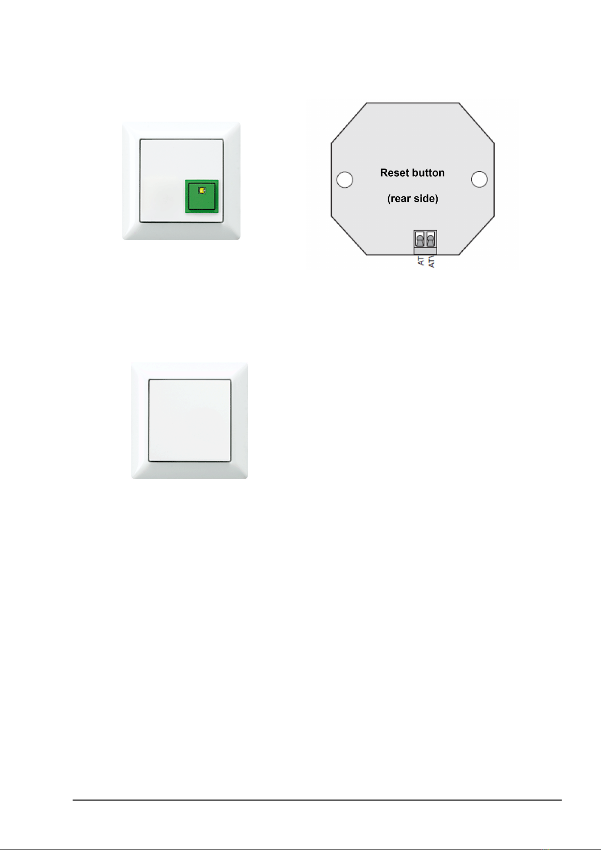
•Reset button NRS .. 0834 AT ..
•Power supply NRS .. 0834 NT ..
Only included in the emergency system set with UPS (NRS .. 0834-2 ..):
•UPS module NRS .. 0834 USV ..
Available separately:
•Service unit NRS .. 0834 DZE ..
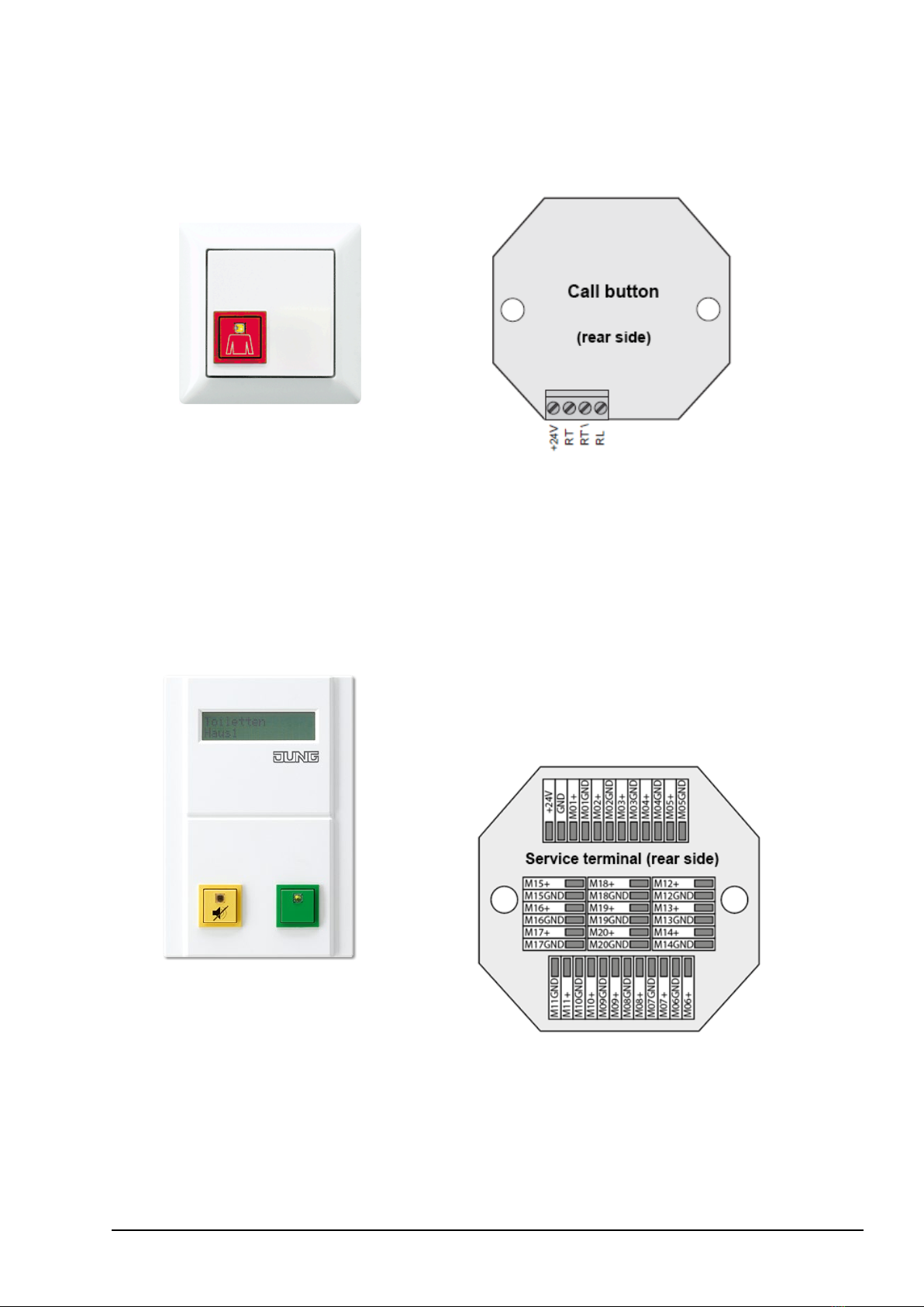
•Call button NRS .. 0834 RT ..
•Service terminal NRS DZT 20 WW
•Surface-mounted housing for service terminal NRS DZT AP WW
•Deflexion pulley set NRS ULR 0834
Spare parts:
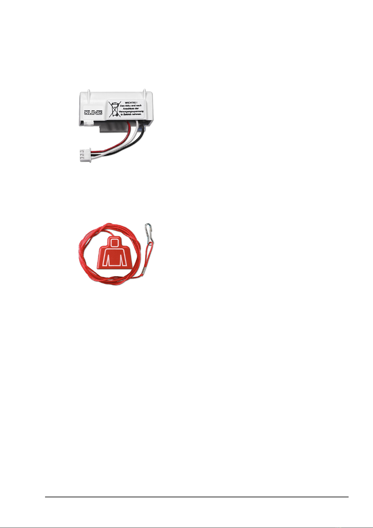
•Accumulator for UPS module NRS AKKU 130
•Pull cord ZS-34 KO5S
Functional description
When an emergency call is triggered with the pull cord, the red light on the push-button
confirms the successful call. The emergency call is indicated visually and acoustically by
the emergency signal. In stand-by mode, a light makes it easier to find the pull cord push-
button.
For other use cases, the visual and acoustic call can be transformed into a continuous
signal, for example, using a jumper. It is also possible to disable the acoustic call.
The unmonitored call can be sent from the emergency signal via a floating contact.
Pressing the reset button stops the emergency call.
If there is no superordinate emergency power supply, the UPS module must be used. The
UPS module ensures that the emergency call is triggered even in the event of power
failure. The accumulator included is easy to replace and available as a spare part. This
emergency power supply is monitored, every disruption is reported.
In battery mode, a short acoustic signal is sent to the emergency signal every 12 seconds.
Two short acoustic signals every 12 seconds are sent to the emergency signal to indicate
an accumulator disturbance.

3
The optional service unit serves to monitor call forwarding. The service unit would not only
indicate the emergency call acoustically but also visually. The call can be muted for
20 seconds or the additional call in the office disabled in absence.
The optional call button also includes lights to be found more easily and to confirm a
successful emergency call.
The service terminal shows unmonitored calls of several emergency calls centrally. It
reports the emergency calls acoustically and visually as plain text. Just as for the service
unit, call forwarding can de disabled on the service terminal in absence or interrupted for
20 seconds. Surface-mounted housing is optionally available.
In accordance with the Dutch standard NEN 1814, the length of the pull cord of the push-
button can be extended to 20 m using the deflexion pulley set. In Germany, this extension
is not obligatory but could be deemed necessary in certain cases. When the pull cord is
installed using the deflexion pulley set, even a person lying in the floor can send an
emergency call pulling at any point of the cord.
The emergency call system is ready for operation as soon as power is supplied. The UPS
module is only able to fully switch to emergency power supply if it was connected to supply
voltage for several hours. It could be up to 6 hours, depending on how long the
accumulator has been charged.

4
Device overview
Emergency signal
NRS .. 0834 RM ..
Visual and acoustic call identification, floating
contact
+24VE +24V external
GNDE GND external
RT Call button
BL Status light confirming successful call
AT Reset button
KA Make contact
KR Break contact
KW Contact input
M Service unit terminal
GND Power supply –
+24V Power supply +
The external connections are intended for downstreamed
components (pull cord push-buttons, reset buttons, ...).
Pull cord push-button
NRS .. 0834 ZT ..
Pull cord push-button with status lights
RLWC Call light WC call
RTWC Pull cord push button WC call (IN)
RTWC\ Pull cord push button WC call (OUT)
+24V Power supply +

5
Reset button
NRS .. 0834 AT ..
Reset button for call silencing
AT Reset button (IN)
AT\ Reset button (OUT)
Power supply
NRS .. 0834 NT ..
With blank cover for flush-mounted installation

6
Only included in the emergency
system set with UPS:
UPS module
NRS .. 0834 USV ..
Optional UPS module for independent
emergency power supply. The plug connector
is to be connected after commissioning. Full
capacity is reached when charged for several
hours. Operation and disturbance of the
accumulator are monitored and reported.
+24V OUT +24V external + (OUT)
GND GND external – (OUT)
M Emergency signal terminal
GND Power supply – (IN)
+24V IN Power supply + (IN)
The set does not include:
Service unit
NRS .. 0834 DZE ..
Optional operation and control unit with
acoustic and visual call, call suppression and
call interruption 20 seconds.
+24V Power supply +
GND Power supply –
M Connection (to emergency signal)

7
The set does not include:
Call button
NRS .. 0834 RT ..
Optional call button with status lights
+24V Power supply +
RT Pull cord push button WC call (IN)
RT\ Pull cord push button WC call (OUT)
RL Call light WC call
The set does not include:
Service terminal
NRS DZT 20 WW
Optional module for unmonitored forwarding of
up to 20 calls. Separate terminals for
20 circuits for closed and open circuit mode.
An additional power supply NRS .. NT 834 .. is
required. A computer and the operating system
Windows is required for configuration.
+24V Power supply +
GND Power supply –
M .. + Reporting circuit +
M .. GND Reporting circuit –

8
The set does not include:
Surface-mounted housing for service
terminal
NRS DZT AP WW
Measurements: 100 x 145 x 25 mm
(W x H x D)
The set does not include:
Deflexion pulley set
NRS ULR 0834
Deflexion pulley set, 20 meters of cord length.
Even a person lying on the floor is able to
reach the pull cord push-button using the
deflexion pulley set. In accordance with the
Dutch standard NEN 1814.

9
Spare part:
Accumulator for UPS module
NRS AKKU 130
Replacement accumulator for the UPS module
Spare part:
Pull cord
ZS-34 KO5S
Pull cord for pull inserts

10
Application
•Emergency system for bathrooms for people with disabilities, in accordance with
DIN VDE 0834
•Acoustic and visual reporting of the call
•Permanent or intermittent sound
•Call triggered via floating contact
•Pull cord push-button with status light
•Reset button
•Power supply
•Only included in the emergency system set with UPS (NRS .. 0834-2 ..):
UPS module for bridging power failures
•Optional service unit with acoustic and visual call, call suppression and call interruption
20 seconds.
•Optional call button with status light
Safety instructions
!
Mounting, installation and commissioning is only permitted for electricians!
When working on systems supplied with AC 230 V, the safety requirements in accordance
with DIN VDE 0100 must be observed.
When installing the emergency system the general safety regulations for
telecommunication systems must be observed according to DIN VDE 0800:
•separate cable routing for mains voltage and extra-low voltage
•minimum distance of 10 cm when cables are routed jointly
•use of separators between high and extra low voltage power lines in cable duct used
jointly
•use of standard telecom cables, e.g. J-Y (St) Y 2x2x0.6
•only when power is off may all connection cables may be connected or disconnected
!
Measures for protection against lightning might be required.

11
Battery safety instructions
!
WARNING! Improper handling of batteries can result in explosion, fire or chemical burn
due to leakage.
•Do not heat or throw batteries into fire.
•Do not reverse polarity, short-circuit or recharge batteries.
•Do not deform or disassemble batteries.
•Replace batteries only with an identical or equivalent type.
•Remove empty batteries immediately and dispose of in an environmentally friendly
manner.
Settings
Settings on the emergency signal
Jumper 1 (JP1)
closed = activated buzzer of the
emergency signal
open = deactivated buzzer
(factory settings)
Jumper 2 (JP2)
closed = signal light and buzzer (also
service unit) with permanent sound
(factory settings)
open = signal light and buzzer intermittent
(also service unit)

12
Installation
Details
•in flush-mounted box
•Installation note UPS module: installation into deep flush box
Installation height in accordance with DIN VDE 0834
(call systems in hospitals, nursing homes and similar facilities)
•Pull cord push-button min. installation height: at least 20 cm
above the shower head
•Operating devices 0.7 to 1.5 m above the floor
•Operating devices with text 1.5 to 1.7 m above the floor
•Devices with installation units 1.6 to 1.8 m above the floor
•Signal lights and text displays 1.5 to 2.2 m above the floor
DIN 18024-2 “Accessibility” also prescribes to install operational elements for wheelchair
users at a height of 0.85 m.
Installation and connection of calling systems is only permitted for trained electricians.
Installation
Installation above the supporting frame without claws
According to DIN VDE 0834 wearing components, i.e. batteries and accumulators, must
be replaced once a year.
Disconnect plug connector before changing the accumulator or decommissioning the
emergency system. This will prevent the accumulator from discharging and short-circuits
during the decommissioning of the accumulator.

13
Installation
Wiring of standard system

14
Connection diagram
Technical data
General
Input voltage: AC 230 V
Ambient temperature: +5 ... +40 °C
Wire: telecom cable J-Y(St) Y 2x2x0.6
Distance emergency signal and service unit: max. 500 m
Connection diameter: single wire, 0.3 ... 1.4 mm
Power supply: 24 V / 250 mA, installation in flush-mounted box 58 mm Ø, cover
Emergency signal: installation in flush-mounted box 58 mm Ø, cover
floating relay contact, 2-way, 24 V / 2 A
Pull cord push-button, reset button,
service unit, call button, UPS module
(only included in emergency system set
with UPS: NRS .. 0834-2 ..): installation in flush-mounted box 58 mm Ø, cover
UPS module
Maximum load, mains-operated: 250 mA
Battery-operated
Output voltage: DC 22.8 V, ± 10 %
Rated load for 1 hour: 130 mA
Maximum load for 15 minutes: 300 mA

15
Example wiring plan:
Emergency system set with additional emergency signal
RT, AT, 24 V and GND are connected in parallel. Typical use case for bathrooms which
are accessible from the corridor but with some distance to the main entrance. One
emergency signal reports from above the bathroom door, another from the main corridor.

16
Example wiring plan:
Emergency system set with additional call button
The additional call button is monitored. Here, the built-in status light gives feedback. For
the function of the status light to be in accordance with the norms, there must not be more
than 3 call or pull cord push-button.

17
Example wiring plan:
Emergency system set with additional pull cord push-button
An additional pull cord push-buttons are available for the emergency system set. For the
function of the status light to be in accordance with the norms, there must not be more
than 3 call or pull cord push-button.

18
Example wiring plan:
Emergency system set with additional reset button
Reset button are connected in parallel.
Example wiring plan:
Emergency system set with additional service unit
Up to 2 service units can be connected in parallel.

19
Example wiring plan: Call triggered by additional push-buttons
Triggering the call additional using another push-button (e.g. in the toilet support bracket)
is possible.
For this, RT must be connected via an NC contact.
The call is triggered at the interruption.

20
Example wiring plan: Unmonitored call
The emergency signals have a floating relay contact (DC 24 V, 1 A) which is suited for
unmonitored calls.
Other manuals for NRS 0834 Series
1
This manual suits for next models
11
Table of contents
Other Jung Security System manuals
Popular Security System manuals by other brands

Melaleuca
Melaleuca Home Security quick start guide

Pima
Pima Sentinel Installation and configuration guide

SAFE-T-ALERT
SAFE-T-ALERT 85-741 user manual

Smanos
Smanos SS1005 user manual

Concept Smoke Screen
Concept Smoke Screen TITANIUM Ti70 Installation and operation manual

Tyco
Tyco Visonic TOWER 10 AM installation instructions