oIn order to change further between operating modes A, B, C and D, press operating mode
button again for longer than 1 second.
Teaching radio transmitter in receiver in operating modes A, C or D
In order for a radio receiver to understand a radio telegram from the radio transmitter, the
receiver has to "learn" this radio telegram. A channel of the radio transmitter can be taught in
any number of receivers. The teaching procedure only results in an assignment in the radio
receiver.
When teaching a transmitter, the range of the receiver is reduced to about 5 m. The distance
between the receiver and the transmitter being taught should therefore be between 0.5 m and 5
m.
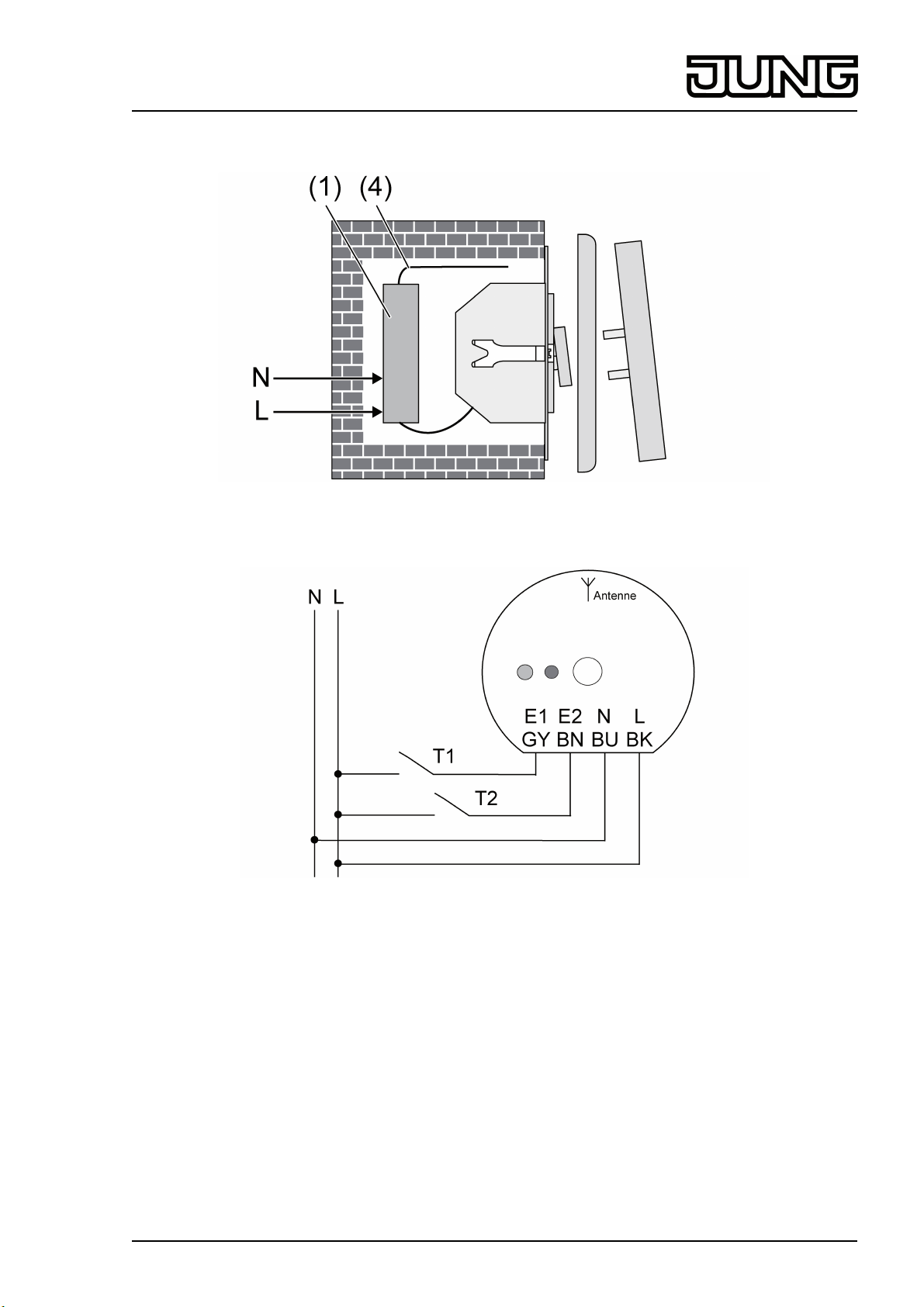
oSwitch receiver to programming mode (see instructions for radio receiver).
oPress connected push-button or switch for longer than 1 second.
oExit programming mode of the receiver (see instructions for the radio receiver).
The radio transmitter has now been taught in the radio receiver.
Teaching radio transmitter in receiver in operating mode B
iBecause the switching telegrams in operating mode B are not suitable for teaching, the
operating mode has to be changed temporarily.
iThis operating mode is not suitable for activation of radio push-button actuators.
oSet transmitter to operating mode A.
oSwitch receiver to programming mode (see instructions for radio receiver).
oPress connected push-button or switch for longer than 1 second.
oExit programming mode of the radio receiver (see instructions for the radio receiver).
oSet radio transmitter to operating mode B.
The radio transmitter has now been taught in the radio receiver.
6 Technical data
Rated voltage AC 230V~
Mains frequency 50 / 60Hz
Ambient temperature -20 ... +55°C
Dimensions Ø×H 52×23 mm
Radio frequency 433.05MHz ... 434.79MHz
Transmission capacity < 10mW
Transmitting range in free field typ. 100m
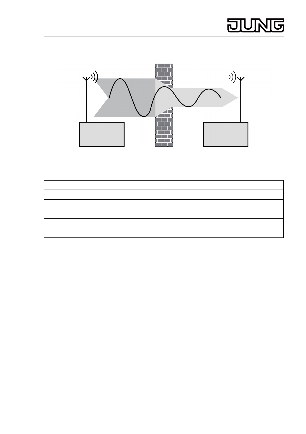
7 Troubleshooting
Radio receiver does not respond, or only sometimes.
Cause: Radio range exceeded. Structural obstacles reduce the range.
Check the installation situation.
Check routing of antenna. Laying the antenna stretched out increases the range.
Using a radio repeater.
8 Conformity
Albrecht Jung GmbH & Co. KG hereby declares that the radio system type
Art. No. FUS22UP
corresponds to the directive 2014/53/EU. You can find the full article number on the device. The
complete text of the EU Declaration of Conformity is available under the Internet address:
www.jung.de/ce
9 Warranty
The warranty follows about the specialty store in between the legal framework as provided for
by law.
9/10
82547943
J0082547943 04.08.2016
Radio Management
Universal radio transmitter, L conductor