Vega VEGABAR 86 User manual

Operating Instructions
Submersible pressure transmitter with
ceramic measuring cell
VEGABAR 86
4 … 20 mA
Document ID: 45506

2
Contents
VEGABAR 86 • 4 … 20 mA
45506-EN-230914
Contents
1 About this document ............................................................................................................... 4
1.1 Function ........................................................................................................................... 4
1.2 Target group ..................................................................................................................... 4
1.3 Symbols used................................................................................................................... 4
2 For your safety ......................................................................................................................... 5
2.1 Authorised personnel ....................................................................................................... 5
2.2 Appropriate use................................................................................................................ 5
2.3 Warning about incorrect use............................................................................................. 5
2.4 General safety instructions............................................................................................... 5
2.5 Conformity........................................................................................................................ 5
2.6 NAMUR recommendations .............................................................................................. 6
2.7 Installation and operation in the USA and Canada ........................................................... 6
2.8 Environmental instructions ............................................................................................... 6
3 Product description ................................................................................................................. 7
3.1 Conguration.................................................................................................................... 7
3.2 Principle of operation........................................................................................................ 7
3.3 Packaging, transport and storage................................................................................... 10
3.4 Accessories.................................................................................................................... 11
4 Mounting................................................................................................................................. 12
4.1 General instructions ....................................................................................................... 12
4.2 Ventilation and pressure compensation.......................................................................... 14
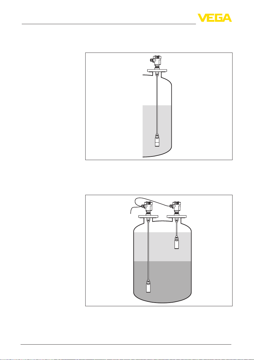
4.3 Level measurement........................................................................................................ 17
4.4 External housing ............................................................................................................ 17
5 Connecting to power supply................................................................................................. 18
5.1 Preparing the connection ............................................................................................... 18
5.2 Connecting..................................................................................................................... 19
5.3 Single chamber housing................................................................................................. 20
5.4 Housing IP66/IP68 (1 bar) .............................................................................................. 21
5.5 External housing ............................................................................................................ 22
5.6 Switch-on phase............................................................................................................. 23
6 Set up with the display and adjustment module ................................................................ 24
6.1 Insert display and adjustment module............................................................................ 24
6.2 Adjustment system......................................................................................................... 25
6.3 Measured value indication.............................................................................................. 26
6.4 Parameter adjustment - Quick setup .............................................................................. 27
6.5 Parameter adjustment - Extended adjustment................................................................ 27
6.6 Menu overview ............................................................................................................... 39
6.7 Save parameter adjustment data.................................................................................... 40
7 Setup with PACTware............................................................................................................. 41
7.1 Connect the PC.............................................................................................................. 41
7.2 Parameterization ............................................................................................................ 41
7.3 Save parameter adjustment data.................................................................................... 42
8 Set up with other systems .................................................................................................... 43
8.1 DD adjustment programs ............................................................................................... 43
8.2 Field Communicator 375, 475 ........................................................................................ 43
9 Diagnostics and servicing .................................................................................................... 44

3
Contents
VEGABAR 86 • 4 … 20 mA
45506-EN-230914
9.1 Maintenance .................................................................................................................. 44
9.2 Diagnosis function.......................................................................................................... 44
9.3 Rectify faults................................................................................................................... 46
9.4 Exchange process module on version IP68 (25 bar) ...................................................... 47
9.5 Exchanging the electronics module................................................................................ 48
9.6 Software update ............................................................................................................. 48
9.7 How to proceed if a repair is necessary.......................................................................... 49
10 Dismount................................................................................................................................. 50
10.1 Dismounting steps.......................................................................................................... 50
10.2 Disposal ......................................................................................................................... 50
11 Supplement ............................................................................................................................ 51
11.1 Technical data ................................................................................................................ 51
11.2 Calculation of the total deviation..................................................................................... 61
11.3 Practical example........................................................................................................... 62
11.4 Dimensions .................................................................................................................... 64
11.5 Industrial property rights................................................................................................. 72
11.6 Trademark ...................................................................................................................... 72
Safety instructions for Ex areas:
TakenoteoftheExspecicsafetyinstructionsforExapplications.
These instructions are attached as documents to each instrument
with Ex approval and are part of the operating instructions.
Editing status: 2023-09-01

4
1 About this document
VEGABAR 86 • 4 … 20 mA
45506-EN-230914
1 About this document
1.1 Function
This instruction provides all the information you need for mounting,
connection and setup as well as important instructions for mainte-
nance,faultrectication,safetyandtheexchangeofparts.Please
read this information before putting the instrument into operation and
keep this manual accessible in the immediate vicinity of the device.
1.2 Target group
This operating instructions manual is directed to trained personnel.
Thecontentsofthismanualmustbemadeavailabletothequalied
personnel and implemented.
1.3 Symbols used
Document ID
This symbol on the front page of this instruction refers to the Docu-
ment ID. By entering the Document ID on www.vega.com you will
reach the document download.
Information, note, tip: This symbol indicates helpful additional infor-
mation and tips for successful work.
Note: This symbol indicates notes to prevent failures, malfunctions,
damage to devices or plants.
Caution: Non-observance of the information marked with this symbol
may result in personal injury.
Warning: Non-observance of the information marked with this symbol
may result in serious or fatal personal injury.
Danger: Non-observance of the information marked with this symbol
results in serious or fatal personal injury.
Ex applications
This symbol indicates special instructions for Ex applications.
• List
The dot set in front indicates a list with no implied sequence.
1 Sequence of actions
Numbers set in front indicate successive steps in a procedure.
Disposal
This symbol indicates special instructions for disposal.

5
2 For your safety
VEGABAR 86 • 4 … 20 mA
45506-EN-230914
2 For your safety
2.1 Authorised personnel
All operations described in this documentation must be carried out
only by trained and authorized personnel.
During work on and with the device, the required personal protective
equipment must always be worn.
2.2 Appropriate use
Model VEGABAR 86 is a pressure transmitter for level and gauge
measurement.
Youcannddetailedinformationabouttheareaofapplicationin
chapter " Product description".
Operational reliability is ensured only if the instrument is properly
usedaccordingtothespecicationsintheoperatinginstructions
manual as well as possible supplementary instructions.
2.3 Warning about incorrect use
Inappropriate or incorrect use of this product can give rise to applica-
tion-specichazards,e.g.vesseloverllthroughincorrectmounting
or adjustment. Damage to property and persons or environmental
contamination can result. Also, the protective characteristics of the
instrument can be impaired.
2.4 General safety instructions
This is a state-of-the-art instrument complying with all prevailing
regulations and directives.The instrument must only be operated in
atechnicallyawlessandreliablecondition.Theoperatingcompany
is responsible for the trouble-free operation of the instrument.When
measuring aggressive or corrosive media that can cause a danger-
ous situation if the instrument malfunctions, the operating company
has to implement suitable measures to make sure the instrument is
functioning properly.
The safety instructions in this operating instructions manual, the
national installation standards as well as the valid safety regulations
and accident prevention rules must be observed.
For safety and warranty reasons, any invasive work on the device
beyond that described in the operating instructions manual may be
carried out only by personnel authorised by us. Arbitrary conversions
ormodicationsareexplicitlyforbidden.Forsafetyreasons,onlythe
accessoryspeciedbyusmustbeused.
To avoid any danger, the safety approval markings and safety tips on
the device must also be observed.
2.5 Conformity
The device complies with the legal requirements of the applicable
country-specicdirectivesortechnicalregulations.Weconrmcon-
formity with the corresponding labelling.

6
2 For your safety
VEGABAR 86 • 4 … 20 mA
45506-EN-230914
The corresponding conformity declarations can be found on our
homepage.
2.6 NAMUR recommendations
NAMUR is the automation technology user association in the process
industry in Germany. The published NAMUR recommendations are
acceptedasthestandardineldinstrumentation.
ThedevicefullstherequirementsofthefollowingNAMURrecom-
mendations:
• NE 21 – Electromagnetic compatibility of equipment
• NE 43 – Signal level for fault information from measuring transduc-
ers
• NE53–Compatibilityofelddevicesanddisplay/adjustment
components
• NE107–Self-monitoringanddiagnosisofelddevices
For further information see www.namur.de.
2.7 Installation and operation in the USA and
Canada
This information is only valid for USA and Canada. Hence the follow-
ing text is only available in the English language.
Installations in the US shall comply with the relevant requirements of
the National Electrical Code (ANSI/NFPA 70).
Installations in Canada shall comply with the relevant requirements of
the Canadian Electrical Code
A Class 2 power supply unit has to be used for the installation in the
USA and Canada.
2.8 Environmental instructions
Protection of the environment is one of our most important duties.
That is why we have introduced an environment management system
with the goal of continuously improving company environmental pro-
tection.Theenvironmentmanagementsystemiscertiedaccording
to DIN EN ISO 14001.
Pleasehelpusfullthisobligationbyobservingtheenvironmental
instructions in this manual:
• Chapter " Packaging, transport and storage"
• Chapter " Disposal"

7
3 Product description
VEGABAR 86 • 4 … 20 mA
45506-EN-230914
3 Product description
3.1 Conguration
The scope of delivery encompasses:
• VEGABAR 86 pressure transmitter
• Ventilation valves, closing screws – depending on version (see
chapter " Dimensions")
The further scope of delivery encompasses:
• Documentation
– Quick setup guide VEGABAR 86
– Testcerticateforpressuretransmitters
– Instructions for optional instrument features
– Ex-specic"Safety instructions" (with Ex versions)
– Ifnecessary,furthercerticates
Information:
Optional instrument features are also described in this operating
instructions manual.The respective scope of delivery results from the
orderspecication.
Thetypelabelcontainsthemostimportantdataforidenticationand
use of the instrument:
• Instrument type
• Information about approvals
• Congurationinformation
• Technical data
• Serial number of the instrument
• QRcodefordeviceidentication
• Numerical code for Bluetooth access (optional)
• Manufacturer information
Tondorderdata,documentsorsoftwarerelatedtoyourdevice,you
have the following options:
• Move to " www.vega.com"andenterinthesearcheldtheserial
number of your instrument.
• Scan the QR code on the type label.
• Open the VEGA Tools app and enter the serial number under "
Documentation".
3.2 Principle of operation
The VEGABAR 86 is a submersible pressure transmitter for level
measurementinwells,basinsandopenvessels.Itsgreatexibility
throughdierentcableandtubeversionsallowstheinstrumenttobe
usedinmanydierentapplications.
Measured products are liquids.
Depending on the instrument version and measurement setup, meas-
ured products can also be viscous or contain abrasive substances.
Scope of delivery
Type label
Documents and software
Application area
Measured products

8
3 Product description
VEGABAR 86 • 4 … 20 mA
45506-EN-230914
The VEGABAR 86 is suitable for the measurement of the following
process variables:
• Level
Fig. 1: Level measurement with VEGABAR 86
Depending on the version, the VEGABAR 86 is also suitable for
electronicdierentialpressuremeasurement.Forthis,theinstrument
is combined with a Secondary Device.
Fig. 2: Electronic dierential pressure measurement via a Primary/Secondary
combination
Youcannddetailedinformationintheoperatinginstructionsofthe
respective Secondary Device.
Measured variables
Electronicdierential
pressure

9
3 Product description
VEGABAR 86 • 4 … 20 mA
45506-EN-230914
The sensor element is the CERTEC®measuring cell with robust
ceramicdiaphragm.Theprocesspressuredeectstheceramic
diaphragm and causes a capacitance change in the measuring cell.
This capacitance change is converted into an electrical signal and
outputted as measured value via the output signal.
The measuring cell is available in two sizes:
• CERTEC®(ø 28 mm) with sensor 32 mm
• Mini-CERTEC®(ø 17.5 mm) with sensor 22 mm
A temperature sensor in the ceramic diaphragm of the CERTEC®or
on the ceramic base of the Mini-CERTEC®measuring cell detects the
actual process temperature.The temperature value is output via:
• The display and adjustment module
• The current output or the additional current output
• The digital signal output
Even extreme jumps in process temperature are immediately de-
tected by the CERTEC®measuring cell. The values in the ceramic
diaphragm are compared with those on the ceramic base body. Within
a few measuring cycles, the intelligent sensor electronics compen-
sates for otherwise unavoidable measurement deviations caused by
temperature shocks in the range. Depending on the adjusted damp-
ing, these cause only slight and brief changes in the output signal. 1)
The measuring cell design depends on the selected pressure type.
Relative pressure: the measuring cell is open to the atmosphere.
The ambient pressure is detected in the measuring cell and compen-
sated.Itthushasnoinuenceonthemeasuredvalue.
Absolute pressure: the measuring cell contains vacuum and is
encapsulated. The ambient pressure is not compensated and does
henceinuencethemeasuredvalue.
Relative pressure, climate-compensated: the measuring cell is
evacuated and encapsulated. The ambient pressure is detected
through a reference sensor in the electronics and compensated. It
thushasnoinuenceonthemeasuredvalue.
The following illustration shows the installation of the ceramic measur-
ing cell in the sensor as well as the sealing concept.
Measuring system pres-
sure
Measuring system tem-
perature
Pressure types
Seal concept
1) At temperatures above 100 °C the function is automatically deactivated, at
temperatures below 95 °C it is automatically reactivated.

10
3 Product description
VEGABAR 86 • 4 … 20 mA
45506-EN-230914
1
2
3
4
5
Fig. 3: Front-ush installation of the ceramic measuring cell with double seal
1 Housing, sensor
2 Measuring cell
3 Lateral seal for measuring cell
4 Additional, front seal for measuring cell
5 Diaphragm
3.3 Packaging, transport and storage
Your instrument was protected by packaging during transport. Its
capacity to handle normal loads during transport is assured by a test
based on ISO 4180.
The packaging consists of environment-friendly, recyclable card-
board. For special versions, PE foam or PE foil is also used. Dispose
of the packaging material via specialised recycling companies.
Transport must be carried out in due consideration of the notes on the
transport packaging. Nonobservance of these instructions can cause
damage to the device.
The delivery must be checked for completeness and possible transit
damage immediately at receipt. Ascertained transit damage or con-
cealed defects must be appropriately dealt with.
Up to the time of installation, the packages must be left closed and
stored according to the orientation and storage markings on the
outside.
Unless otherwise indicated, the packages must be stored only under
the following conditions:
• Not in the open
• Dry and dust free
• Not exposed to corrosive media
• Protected against solar radiation
• Avoiding mechanical shock and vibration
• Storage and transport temperature see chapter " Supplement -
Technical data - Ambient conditions"
• Relative moisture 20 … 85 %
With instrument weights of more than 18 kg (39.68 lbs) suitable and
approved equipment must be used for lifting and carrying.
Packaging
Transport
Transport inspection
Storage
Storage and transport
temperature
Lifting and carrying

11
3 Product description
VEGABAR 86 • 4 … 20 mA
45506-EN-230914
3.4 Accessories
The instructions for the listed accessories can be found in the down-
load area on our homepage.
The display and adjustment module is used for measured value indi-
cation, adjustment and diagnosis.
The integrated Bluetooth module (optional) enables wireless adjust-
ment via standard adjustment devices.
The interface adapter VEGACONNECT enables the connection of
communication-capable instruments to the USB interface of a PC.
The VEGADIS 82 is suitable for measured value indication of
4 … 20 mA and 4 … 20 mA/HART sensors. It is looped into the signal
cable.
The overvoltage arrester B81-35 is used instead of the terminals in
the single or double chamber housing.
The protective cover protects the sensor housing against soiling and
intense heat from solar radiation.
Screwedangesareavailableindierentversionsaccordingtothe
following standards: DIN 2501, EN 1092-1, BS 10, ASME B 16.5,
JIS B 2210-1984, GOST 12821-80.
Welded sockets are used to connect the devices to the process.
Threaded and hygienic adapters enable simple adaptation of devices
withstandardthreadedttingstoprocess-sidehygieneconnections.
Display and adjustment
module
VEGACONNECT
VEGADIS 82
Overvoltage protection
Protective cover
Flanges
Welded socket, threaded
and hygienic adapter

12
4 Mounting
VEGABAR 86 • 4 … 20 mA
45506-EN-230914
4 Mounting
4.1 General instructions
Note:
For safety reasons, the instrument must only be operated within the
permissibleprocessconditions.Youcannddetailedinformationon
the process conditions in chapter " Technical data" of the operating
instructions or on the type label.
Hence make sure before mounting that all parts of the instrument ex-
posed to the process are suitable for the existing process conditions.
These are mainly:
• Active measuring component
• Processtting
• Process seal
Process conditions in particular are:
• Process pressure
• Process temperature
• Chemical properties of the medium
• Abrasionandmechanicalinuences
Protect your instrument against moisture ingress through the following
measures:
• Use a suitable connection cable (see chapter " Connecting to
power supply")
• Tighten the cable gland or plug connector
• Lead the connection cable downward in front of the cable entry or
plug connector
This applies mainly to outdoor installations, in areas where high
humidity is expected (e.g. through cleaning processes) and on cooled
or heated vessels.
Note:
Make sure that during installation or maintenance no moisture or dirt
can get inside the instrument.
To maintain the housing protection, make sure that the housing lid is
closed during operation and locked, if necessary.
Deviceswiththreadedttingarescrewedintotheprocessttingwith
a suitable wrench via the hexagon.
See chapter " Dimensions" for wrench size.
Warning:
The housing or the electrical connection may not be used for screw-
ing in! Depending on the device version, tightening can cause dam-
age, e. g. to the rotation mechanism of the housing.
Avoid damages on the device by lateral forces, for example by vibra-
tions.Itisthusrecommendedtoxthedeviceswithprocesstting
Process conditions
Protection against mois-
ture
Screwing in
Vibrations

13
4 Mounting
VEGABAR 86 • 4 … 20 mA
45506-EN-230914
thread G½ of plastic at the installation site via a suitable measuring
instrument holder.
If there is strong vibration at the mounting location, the instrument
version with external housing should be used. See chapter " External
housing".
Thepermissibleprocesspressurerangeisspeciedonthetypelabel
with "MWP" (Maximum Working Pressure), see chapter " Congura-
tion".This applies even if a measuring cell with a measuring range
(order-related) higher than the permissible pressure range of the
processttingisinstalled.
Inaddition,atemperaturederatingoftheprocesstting,e.g.with
anges,canlimitthepermissibleprocesspressurerangeaccording
to the respective standard.
The permissible process pressure range is stated on the type label.
The instrument should only be operated with these pressures if the
mountingaccessoryusedalsofullsthesevalues.Thisshouldbeen-
suredbysuitableanges,weldedsockets,tensionringswithClamp
connections, sealings, etc.
Higher process temperatures often mean also higher ambient
temperatures. Make sure that the upper temperature limits stated in
chapter " Technical data" for the environment of the electronics hous-
ing and connection cable are not exceeded.
2
1
Fig. 4: Temperature ranges
1 Process temperature
2 Ambient temperature
Depending on the transmitter, the VEGABAR 86 is supplied with a
protective cap or a transport and mounting protection.
Permissible process
pressure (MWP) - Device
Permissible process
pressure (MWP) - Mount-
ing accessory
Temperature limits
Transport and mounting
protection

14
4 Mounting
VEGABAR 86 • 4 … 20 mA
45506-EN-230914
1
2
Fig. 5: VEGABAR 86, transport and mounting protection
1 Transmitter
2 Transport and mounting protection
Remove this protection after mounting and before setting up the
instrument.
In case of slightly contaminated measured media, the transport and
mounting protection can remain on the instrument as an impact pro-
tection during operation.
4.2 Ventilation and pressure compensation
Thelterelementintheelectronicshousinghasthefollowingfunc-
tions:
• Ventilation of the electronics housing
• Atmospheric pressure compensation (with relative pressure meas-
uring ranges)
Caution:
Thelterelementcausesatime-delayedpressurecompensation.
When quickly opening/closing the housing cover, the measured value
can change for approx. 5 s by up to 15 mbar.
Foraneectiveventilation,thelterelementmustbealwaysfreefrom
buildup. In case of horizontal mounting, turn the housing so that the
lterelementpointsdownwardaftertheinstrumentisinstalled.This
provides better protection against buildup.
Caution:
Donotuseahigh-pressurecleaner.Thelterelementcouldbedam-
aged, which would allow moisture into the housing.
Thefollowingparagraphsdescribehowthelterelementisarranged
inthedierentinstrumentversions.
Filter element - Function

15
4 Mounting
VEGABAR 86 • 4 … 20 mA
45506-EN-230914
1 2 3
6
6
6 6
6
5
4
Fig. 6: Position of the lter element
1 Plastic, stainless steel single chamber (precision casting)
2 Aluminium - single chamber
3 Stainless steel single chamber (electropolished)
4 Plastic double chamber
5 Aluminium, stainless steel double chamber housing (precision casting)
6 Filter element
With the following instruments a blind plug is installed instead of the
lterelement:
• Instruments in protection IP66/IP68 (1 bar) - ventilation via capillar-
ies in non-detachable cable
• Instruments with absolute pressure
→ Turnthemetalringinsuchawaythatthelterelementpoints
downward after installation of the instrument. This provides better
protection against buildup.
Filter element - Position
Ex d version

16
4 Mounting
VEGABAR 86 • 4 … 20 mA
45506-EN-230914
1
2
Fig. 7: Position of the lter element - Ex d version
1 Rotatable metal ring
2 Filter element
With absolute pressure measuring ranges, a blind plug is used
insteadofthelterelement.
The Second Line of Defense (SLOD) is a second level of the process
separation in form of a gas-tight leadthrough in the housing neck,
preventing products from penetrating into the housing.
With these instruments, the process assembly is completely en-
capsulated. An absolute pressure measuring cell is used so that no
ventilation is required.
With relative pressure measuring ranges, the ambient pressure is
detected and compensated by a reference sensor in the electronics.
1
2
1
2
Fig. 8: Position of the lter element - gastight leadthrough
1 Filter element
2 Gas-tight leadthrough
Filter element - Position
Second Line of Defense

17
4 Mounting
VEGABAR 86 • 4 … 20 mA
45506-EN-230914
1
Fig. 9: Position of the lter element - IP69K version
1 Filter element
Instruments with absolute pressure have a blind plug mounted
insteadofthelterelement.
4.3 Level measurement
Keep the following in mind when setting up the measuring system:
• Donotmounttheinstrumentclosetothellingstreamoremptying
area
• Mount the instrument so that it is protected against pressure
shocks from the stirrer
4.4 External housing
1
2
3
4
Fig. 10: Arrangement measurement loop, external housing
1 Sensor
2 Connection cable sensor, external housing
3 External housing
4 Signal cable
Filter element - Position
IP69K version
Measurement setup
Conguration

18
5 Connecting to power supply
VEGABAR 86 • 4 … 20 mA
45506-EN-230914
5 Connecting to power supply
5.1 Preparing the connection
Always keep in mind the following safety instructions:
• Carryoutelectricalconnectionbytrained,qualiedpersonnel
authorised by the plant operator
• If overvoltage surges are expected, overvoltage arresters should
be installed
Warning:
Only connect or disconnect in de-energized state.
Power supply and current signal are carried on the same two-wire
cable.Theoperatingvoltagecandierdependingontheinstrument
version.
Thedataforpowersupplyarespeciedinchapter"Technical data".
Provide a reliable separation between the supply circuit and the
mains circuits according to DIN EN 61140 VDE 0140-1.
Power the instrument via an energy-limited circuit acc. to IEC 61010-
1, e.g. via Class 2 power supply unit.
Keepinmindthefollowingadditionalfactorsthatinuencetheoperat-
ing voltage:
• Lower output voltage of the power supply unit under nominal load
(e.g. with a sensor current of 20.5 mA or 22 mA in case of fault
signal)
• Inuenceofadditionalinstrumentsinthecircuit(seeloadvaluesin
chapter " Technical data")
The instrument is connected with standard two-wire cable without
shielding. If electromagnetic interference is expected which is above
the test values of EN 61326-1 for industrial areas, shielded cable
should be used.
Use cable with round cross section for instruments with housing and
cable gland. Use a cable gland suitable for the cable diameter to
ensurethesealeectofthecablegland(IPprotectionrating).
If shielded cable is required, we recommend connecting the cable
screening on both ends to ground potential. In the sensor, the cable
screening is connected directly to the internal ground terminal.The
ground terminal on the outside of the housing must be connected to
the ground potential (low impedance).
In Ex systems, the grounding is carried out according to the installa-
tion regulations.
In electroplating plants as well as plants for cathodic corrosion protec-
tionitmustbetakenintoaccountthatsignicantpotentialdierences
exist.This can lead to unacceptably high currents in the cable screen
if it is grounded at both ends.
Safety instructions
Voltage supply
Connection cable
Cable screening and
grounding

19
5 Connecting to power supply
VEGABAR 86 • 4 … 20 mA
45506-EN-230914
Note:
Themetallicpartsoftheinstrument(processtting,sensor,concen-
tric tube, etc.) are connected with the internal and external ground
terminal on the housing. This connection exists either directly via
the conductive metallic parts or, in case of instruments with external
electronics, via the screen of the special connection cable.
Youcanndspecicationsonthepotentialconnectionsinsidethe
instrument in chapter " Technical data".
Metric threads:
In the case of instrument housings with metric thread, the cable
glands are screwed in at the factory. They are sealed with plastic
plugs as transport protection.
Note:
You have to remove these plugs before electrical connection.
NPT thread:
In the case of instrument housings with self-sealing NPT threads, it is
not possible to have the cable entries screwed in at the factory. The
free openings for the cable glands are therefore covered with red dust
protection caps as transport protection.
Note:
Prior to setup you have to replace these protective caps with ap-
proved cable glands or close the openings with suitable blind plugs.
On plastic housings, the NPT cable gland or the Conduit steel tube
must be screwed into the threaded insert without grease.
Max. torque for all housings, see chapter " Technical data".
5.2 Connecting
The voltage supply and signal output are connected via the spring-
loaded terminals in the housing.
Connection to the display and adjustment module or to the interface
adapter is carried out via contact pins in the housing.
Information:
The terminal block is pluggable and can be removed from the
electronics.To do this, lift the terminal block with a small screwdriver
and pull it out. When reinserting the terminal block, you should hear it
snap in.
Proceed as follows:
1. Unscrew the housing lid
2. If a display and adjustment module is installed, remove it by turn-
ing it slightly to the left
3. Loosen compression nut of the cable gland and remove blind
plug
4. Remove approx. 10 cm (4 in) of the cable mantle, strip approx.
1 cm (0.4 in) of insulation from the ends of the individual wires
Cable glands
Connection technology
Connection procedure

20
5 Connecting to power supply
VEGABAR 86 • 4 … 20 mA
45506-EN-230914
5. Insert the cable into the sensor through the cable entry
Fig. 11: Connection steps 5 and 6 - Single chamber housing
6. Insert the wire ends into the terminals according to the wiring plan
Information:
Solidcoresaswellasexiblecoreswithwireendsleevesareinsert-
eddirectlyintotheterminalopenings.Incaseofexiblecoreswithout
end sleeves, press the terminal from above with a small screwdriver,
the terminal opening is then free.When the screwdriver is released,
the terminal closes again.
7. Check the hold of the wires in the terminals by lightly pulling on
them
8. Connect the shielding to the internal ground terminal, connect the
external ground terminal to potential equalisation
9. Tighten the compression nut of the cable entry gland. The seal
ring must completely encircle the cable
10. Reinsert the display and adjustment module, if one was installed
11. Screw the housing lid back on
Theelectricalconnectionisnished.
5.3 Single chamber housing
The following illustration applies to the non-Ex as well as to the Ex ia
version.
Other manuals for VEGABAR 86
14
Table of contents
Other Vega Transmitter manuals

Vega
Vega VEGABAR 82 User manual

Vega
Vega VEGABAR 86 User manual

Vega
Vega VEGAWELL 52 User manual

Vega
Vega VEGABAR 83 User manual

Vega
Vega RMT-10 User manual

Vega
Vega VEGABAR 54 User manual

Vega
Vega VEGABAR 82 User manual

Vega
Vega VEGADIF 85 User manual

Vega
Vega VEGABAR 82 User manual

Vega
Vega VEGADIF 85 User manual

Vega
Vega VEGABAR 82 User manual

Vega
Vega VEGABAR 82 User manual

Vega
Vega VEGABAR 86 User manual

Vega
Vega VEGABAR 51 User manual

Vega
Vega VEGABAR 53 User manual

Vega
Vega VEGABAR 83 User manual

Vega
Vega VEGABAR S 14 User manual

Vega
Vega VEGABAR 86 User manual

Vega
Vega VEGABAR 83 User manual

Vega
Vega VEGABAR 81 User manual