4 Commissioning
4.1 Basic commissioning procedure
Preconditions:
During commissioning, the respective devices must have a distance of 10 to 50 cm to each
other.
Each device can only be part of one network.
The luminaire shall be operated using a Philips Hue Bridge or an Osram Lightify Gateway
and transmitters.
oCommission the luminaire with a bridge or gateway.
oAdd the transmitter to the network of the bridge or gateway.
iIf the transmitter already belongs to a network, reset the transmitter beforehand, see
Chapter 4.6.
iThe procedure depends on the app used and may deviate from the procedure described
herein. Up-to-date information can be found on our website.
oOpen the network of the bridge or gateway.
Philips Hue Bridge Osram Lightify Gateway
Start Philips Hue app. Start Osram Lightify app.
Select "Settings". Select "Devices".
Select "My lamps" Press "+".
Select "Connect new lights". Select "Add lights/plugs".
Select "Automatic search". Press "→".
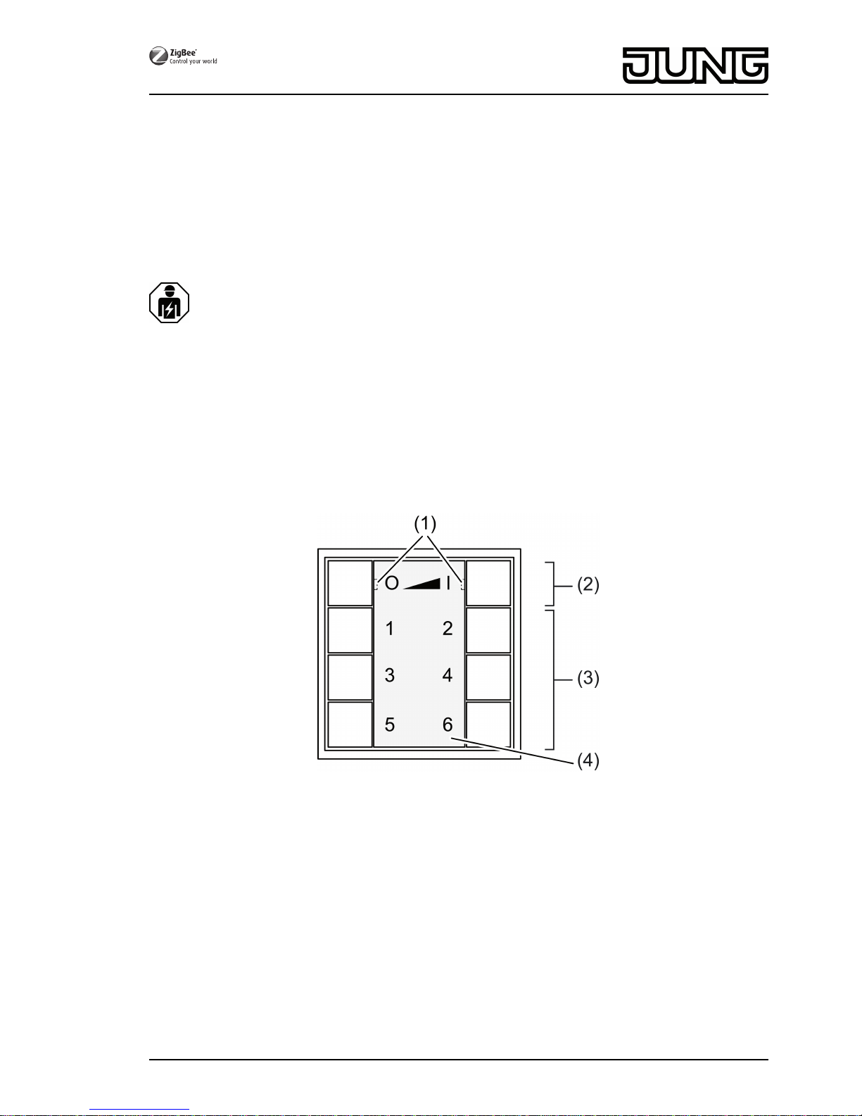
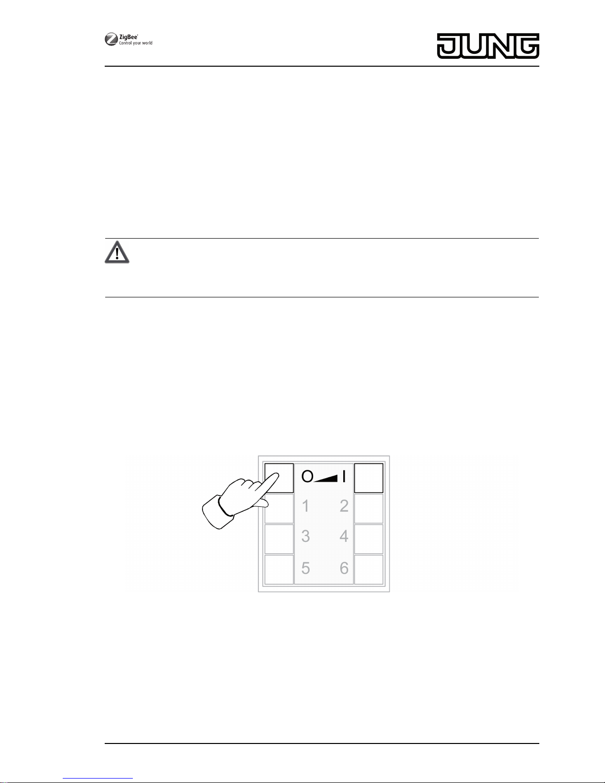
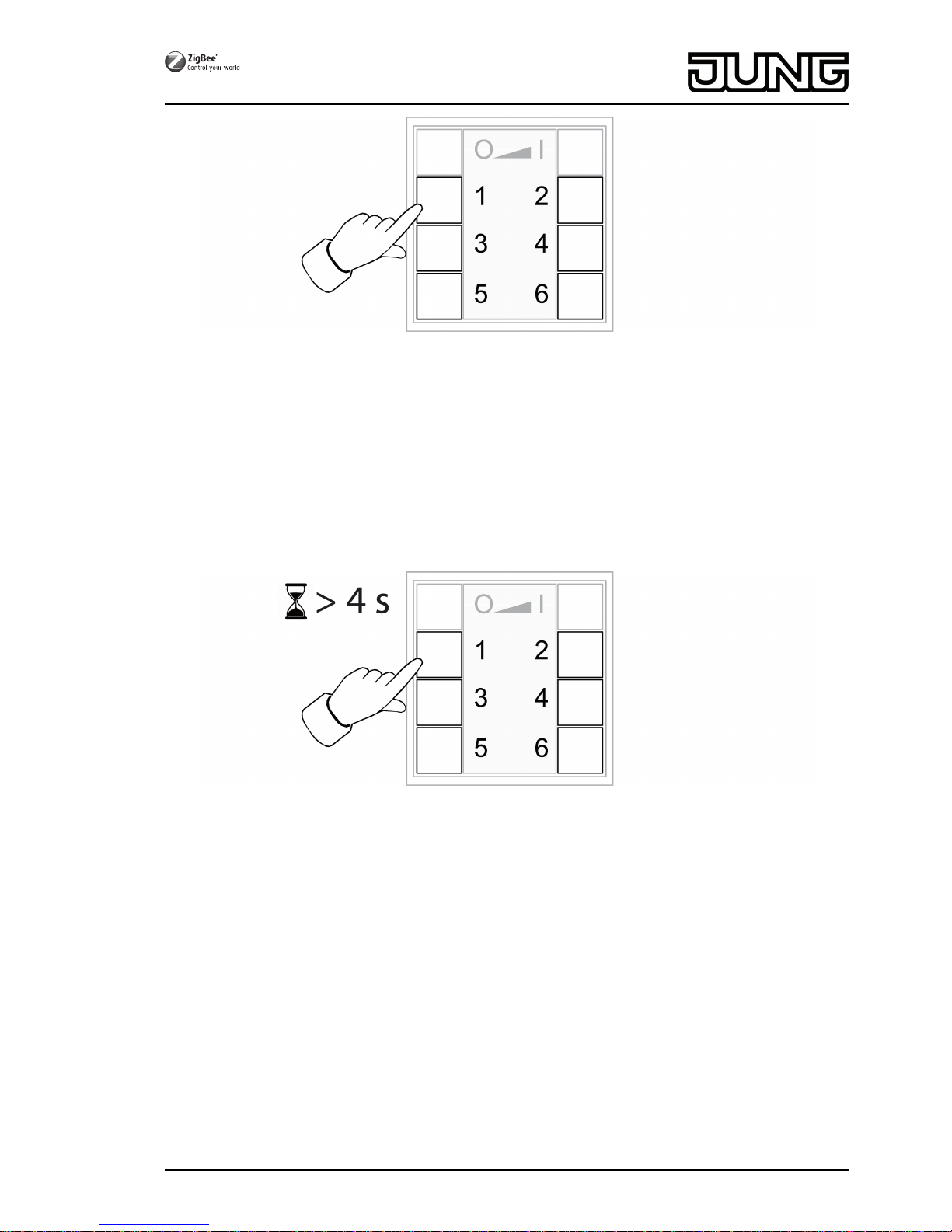
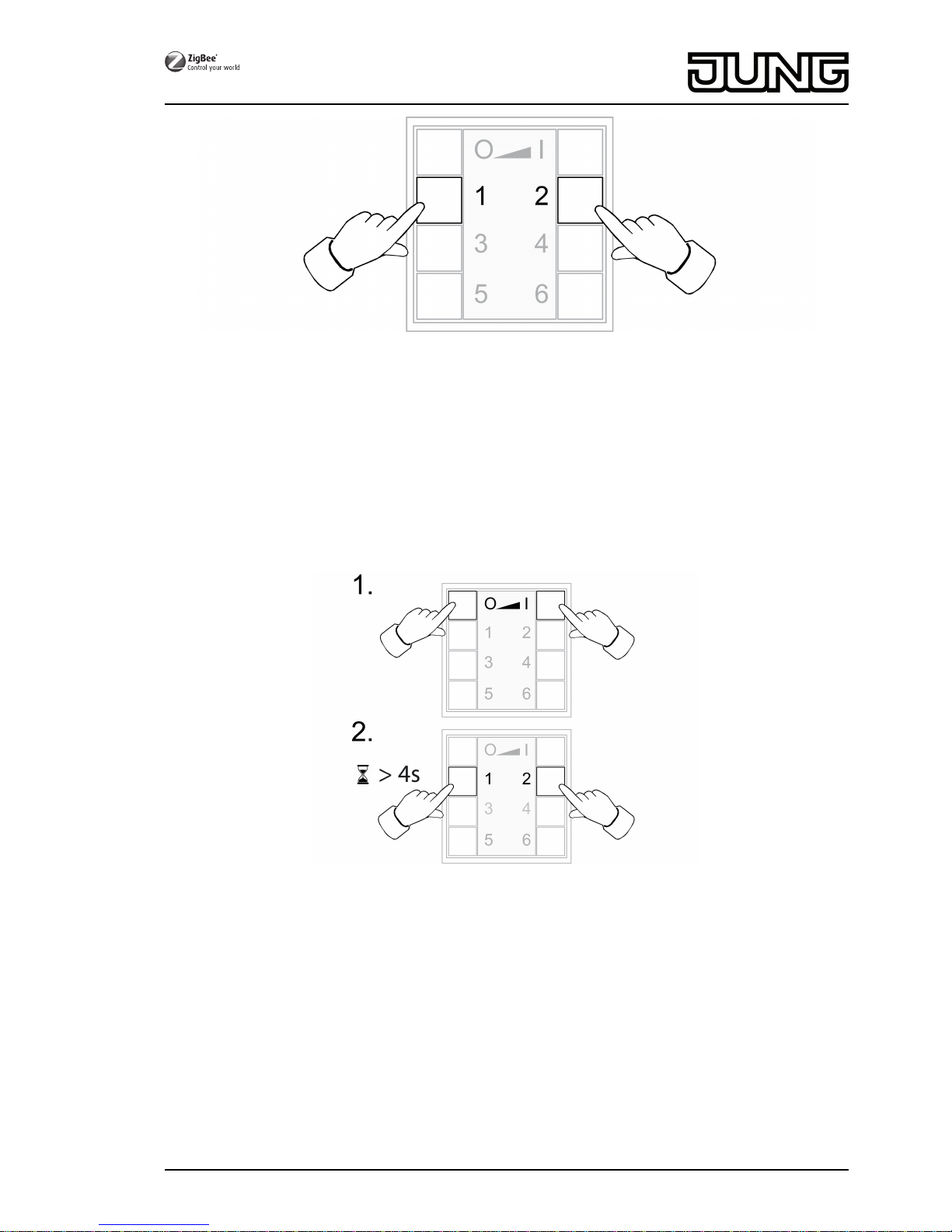
oPress the Ƌ and ƍ buttons on the new transmitter simultaneously until the LEDs
flash green.
iAfter approx. 10 seconds the transmitter searches for an open network.
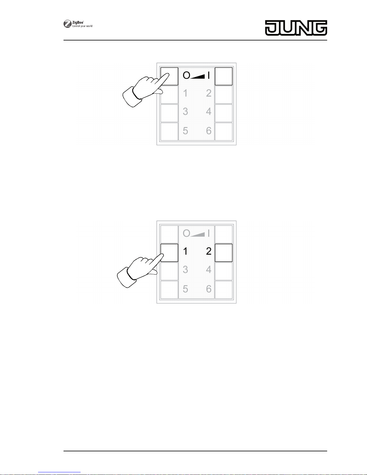
LEDs light up green for 3 seconds. The transmitter has joined the network of the bridge or
gateway.
LEDs flash red quickly for 10 seconds. The transmitter has not joined the network.
oConnect the transmitter to a luminaire, see Chapter 4.2.
The luminaire shall exclusively be operated using a transmitter without connection to a
Philips Hue Bridge or Osram Lightify Gateway.
The luminaire has default settings.
oConnect the luminaire to a transmitter, see chapter 4.2.
or the luminaire belongs to another network.
oReset luminaire, see chapter 4.5.
oConnect the luminaire to a transmitter, see chapter 4.2.
iFor additional luminaires, repeat the corresponding actions.
The luminaire should be operated with several transmitters without a connection to a
Philips Hue Bridge or Osram Lightify Gateway
Precondition:
The luminaire is already connected to a transmitter, see chapter 4.2.
oAdd a new transmitter to the network, see chapter 4.3.
oConnect the luminaire to the new transmitter, see chapter 4.2.
7/17
32596203
J0082596203 23.05.2016
ZigBee radio transmitter module 4-gang