Jungle Jim’s JUNGLE JACK V2 User manual

Jungle Jim’s Accessory Products, Inc. 550 O’Byrne Avenue, Louisville, KY 40223
1-888-844-JIMS or log onto the web site at www.junglejimsap.com Jungle Jack V2 Instructions, Rev. 10/17/22
JUNGLE JACK V2
ASSEMBLY
INSTRUCTIONS
(PATENT PENDING)

Jungle Jim’s Accessory Products, Inc. 550 O’Byrne Avenue, Louisville, KY 40223
1-888-844-JIMS or log onto the web site at www.junglejimsap.com Jungle Jack V2 Instructions, Rev. 10/17/22
IMPORTANT: READ BEFORE OPERATION OF THE JUNGLE JACK
1. Please read ALL instructions before using your Jungle Jack. The following are safety specifics,
but do not limit yourself to just these. Please use common sense!
2. Be sure machine is not running, when using Jungle Jack.
3. Never use Jungle Jack on inclined, uneven or unstable ground. (i.e. grass, dirt, gravel or
soft asphalt)
4. NEVER place your head underneath the machine, while using the Jungle Jack.
5. All personnel must stay clear of the machine while lifting or lowering the machine with
the Jungle Jack.
6. In the event that the Jungle Jack should fall for any reason, be sure that you are not
underneath the machine.
7. When lifting any piece of machinery, make sure the lifting tooth contacts the machine
on a strong part of the frame that will support the weight of the machine (please see
attached drawing).
8. Before implementing the safety arm, place jack stands underneath the mower.
9. DO NOT work on any machine, supported by the Jungle Jack, without the Safety Arm
locked down.
10. The Jungle Jack has a capacity of 800 lbs. at the lifting point. Exceeding this weight
could cause serious injury or death.
DO NOT exceed the rated capacity.
11. Never operate the Jungle Jack while tired or on medication.
Please scan QR Code for video on how to assemble and use
the Jungle Jack V2

Jungle Jim’s Accessory Products, Inc. 550 O’Byrne Avenue, Louisville, KY 40223
1-888-844-JIMS or log onto the web site at www.junglejimsap.com Jungle Jack V2 Instructions, Rev. 10/17/22
LIFTING INSTRUCTIONS
Lifting instructions for the front end of commercial walk behind and zero turn mowers with large baffles on
the deck. Note: Follow this same process when lifting from the rear of the mower. Make sure the tooth
doesn’t come in contact with pulleys or belts when lifting from the rear. This can cause serious damage to
the mower.
Securely connect the Jungle Jack to the mower
deck with the hook as shown.
Apply steady force to the handle to initiate
lifting. While lifting, twist the right grip towards
you to release the safety Arm. For heavy
machines use the foot assist pedal to aid lifting.
Continue applying force until the Jungle Jack is
lying flat on the ground. The safety arm should
fall and lock into place.
DO NOT work on any machine supported by the Jungle
Jack without the safety arm in position. Once work is
complete, twist the right grip again to disengage the
release pin and raise the Jack. The Safety Arm will go
back into storage position once Jack is in upright
position.

Jungle Jim’s Accessory Products, Inc. 550 O’Byrne Avenue, Louisville, KY 40223
1-888-844-JIMS or log onto the web site at www.junglejimsap.com Jungle Jack V2 Instructions, Rev. 10/17/22
JUNGLE JACK PARTS LIST
Item #
Part #
Part Description
QTY
1
JJ-LFAR
Large Foot Assist Reinforcement
1
4
706
1.250 SQ. Tubing Plastic Cap
1
5
208
3/8-16 x 2 ½ ” Hex Cap Screw
3
7
209
3/8-16 x 3” Hex Cap Screw
3
8
803
3/8" x 2¾" Clevis Pin
1
9
805
0.093" x 2" Hitch Pin
1
10
802
3/8" x 2¼" Clevis Pin
1
11
807
1/8" x 1" Cotter Pin
3
12
818
3/8" x 2-7/8" W/ Detent Ring Pin
1
13
JJ-VINYL
3/8" x 1½" x 1¼" Vinyl
1
14
409
¾" 3/4"ID x 1¼" OD Washer
4
15
JJ-FA
FOOT ASSIST
1
16
JJ-TSPACER
TOOTH SPACER
2
17
JJ-V2TOOTH
Jack Tooth
1
18
828
NEW TOOTH SPRING RETURN
2
19
302
3/8"X16 NYLON LOCK NUT
6
20
227
1/4-20X2.25 HEX CAP SCREW
1
21
314
1/4-20 LOCKNUT
2
22
JJ-SAA3
JUNGLE JACK SAFETY ARM
1
23
JJ-QRP
QUICK RELEASE PIN
1
24
JJ-CABLE
PIN RELEASE CABLE
1
25
JJ-SLB
JUNGLE JACK SPRING LOCK BRACKET
1
26
JJ-JB3
Jungle Jack, Brace 3
1
27
JJ-FRAME3
FRAME ASSEMBLY
1
28
JJ-HANDLE
JACK HANDLE
1
29
JJ-CTB
JUNGLE JACK CABLE TENSION BOLT
1
30
829
JACK LOCK PIN SPRING
1
31
260
1/4-20 X 1/2" HEX CAP SCREW
1
32
261
M5X10MM SOCKET CAP SCREW
1
33
262
1/4-20 X 1 3/4 HEX CAP SCREW
1
34
JJ-THAGRIPL
TWIST HANDLE ASSEMBLY LEFT GRIP
1
35
JJ-THAGRIPR
TWIST HANDLE RIGHT GRIP
1
36
912
JACK TIRES
2
37
JJ-THA
TWIST HANDLE ASSEMBLY
1

Jungle Jim’s Accessory Products, Inc. 550 O’Byrne Avenue, Louisville, KY 40223
1-888-844-JIMS or log onto the web site at www.junglejimsap.com Jungle Jack V2 Instructions, Rev. 10/17/22
JUNGLE JIMS JUNGLE JACK ASSEMBLY (For Heavier Mowers)
3
7
37

Jungle Jim’s Accessory Products, Inc. 550 O’Byrne Avenue, Louisville, KY 40223
1-888-844-JIMS or log onto the web site at www.junglejimsap.com Jungle Jack V2 Instructions, Rev. 10/17/22
ASSEMBLY
1. Place part #14 (409) washer onto main frame part (# JJ-
FRAME3) Jack Frame followed by part #36 (912) Tire, then
follow with an additional part #14 (409) washer. Add part #11
(807) cotter pin to secure. Repeat on next side.
2. Slide part #30 (829) lock pin spring
onto part #23(JJ-QRP) quick release pin. Insert from the right
side (in the closest hole to the tires) into the Jack frame side as
shown.
3. Place part #25 (JJ-SLB) spring lock
bracket onto part #23 (JJ-QRP) quick
release pin, behind end of spring. Attach
part #25 (JJ-SLB) spring lock bracket with
part #31 (260) ¼” - 20 x ½”HCS from
inside the frame as shown.
4. Attach part #26 (JJ-JB3) brace to the bottom of
the frame using part #7 (209) 3/8” x 3” HCS and part
#19 (302) 3/8” x 16” Nylon Lock Nut.
5. Attach part #28 (JJ-HANDLE) handle and part #1
(JJ-LFAR) large foot assist to the top of the frame
using part #5 (208) 3/8” x 2 ½ ” HCS and part #19
(302) 3/8” x 16” Nylon Lock Nut in the middle of the
three holes.
*BE SURE TO ROUTE THE (#JJ-CABLE) PIN RELEASE
CABLE BEHIND THE HEX CAP SCREWS

Jungle Jim’s Accessory Products, Inc. 550 O’Byrne Avenue, Louisville, KY 40223
1-888-844-JIMS or log onto the web site at www.junglejimsap.com Jungle Jack V2 Instructions, Rev. 10/17/22
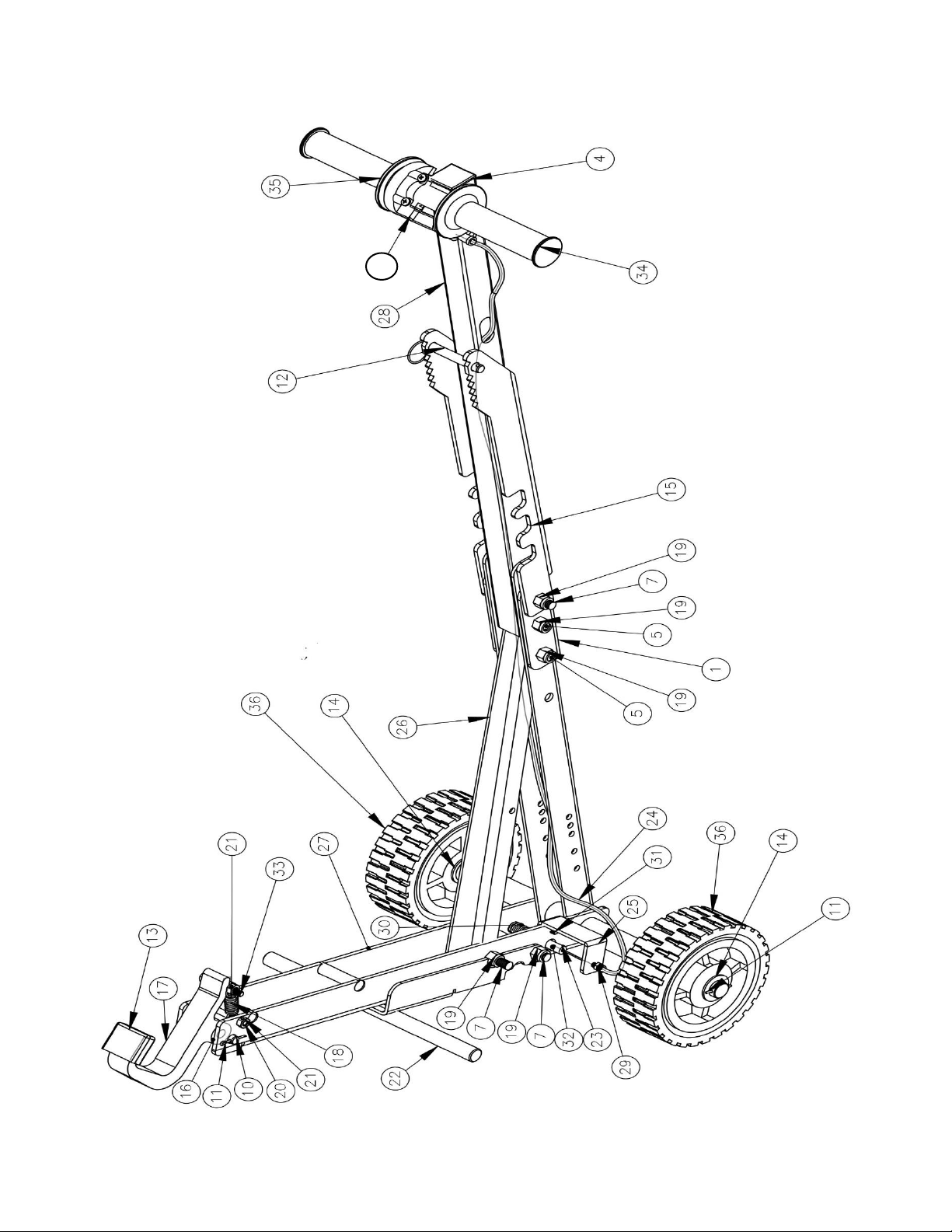
6. Next attach the part #26 (JJ-JB3) brace to the top of the frame
and part #1 (JJ-LFAR) large foot assist using the lowest of the
three holes using part #5 (208) 3/8” x 2 ½ ” HCS and part #19
(302) 3/8” x 16” Nylon Lock Nut.
**Depending on your body stature and weight of your
mower, you may want to have the foot assist higher for
heavier mowers, or lower for lighter mowers.
7.a. For lighter mowers you would then use a
#7 (208) 3/8” x 2 ½ ” HCS and part #19 (302)
3/8” x 16” Nylon Lock Nut at the top of the three consecutive holes
to secure the handle and large foot assist to the frame. Then attach
part #15 (JJ-FA) to the main frame using the hole below the 3
consecutive holes with a #5 (209) 3/8” x 3 ” HCS and part #19 (302)
3/8” x 16” Nylon Lock Nut. See picture to
the left.
b. For heavier mowers you would use
part #7 (209) 3/8” x 3” HCS and part #19
(302) 3/8” x 16” Nylon Lock Nut to
mount part #15 (JJ-FA) foot assist to the
frame and large foot assist using the top
of the three holes. You will end having an extra #5 (208)
3/8” x 2 ½ ” HCS and part #19 (302) 3/8” x 16” Nylon Lock
Nut. See picture to the right.
8. Attach part #22 (JJ-SAA3) Safety
Arm over the Quick Release Pin
then attach using a through the hole above the Quick Release
Pin using part #7 (209) 3/8” x 3” HCS and part #19 (302) 3/8” x
16” Nylon Lock Nut. *** Be sure not to overtighten as the arm
must move freely.

Jungle Jim’s Accessory Products, Inc. 550 O’Byrne Avenue, Louisville, KY 40223
1-888-844-JIMS or log onto the web site at www.junglejimsap.com Jungle Jack V2 Instructions, Rev. 10/17/22
9. Attach part #29 (JJ-CTB) cable tensioner bolt
into part #25 (JJ-SLB) spring lock bracket. See picture
to left.
10. Insert part #24 (JJ-CABLE) through part #29 (JJ-
CTB) cable tensioner bolt and into part #23 (JJ-QRP)
quick release pin. Make sure there is not any slack in
the entire cable line or the pin will not engage. Next,
insert part #32 (261) M5 X 10 MM Socket Head Screw
into #23 (JJ-QRP)
quick release pin and
tighten with provided
Allen Wrench.
Tighten the part #37 Twist handle assembly with a
Philips head Screwdriver. See picture to the right.
Test the Quick Release
Safety Arm by twisting part
#35 (JJ-THAGRIPR) right grip
back towards you and make
sure the quick release pin
retracts. If the Safety Arm
does not release/engage
(fall down), the safety arm
could be too tight. Loosen
the #7 (209) 3/8” x 3” HCS
and part #19 (302) 3/8” x
16” Nylon Lock Nut.
****Hitch Pin Part#9 (805)
and Clevis Pin Part#8 (803)
are still provided in case you wish to use the Jack Safety Arm the traditional version or in
case you break your Cable. Always use the Safety Arm while using the Jungle Jack.

Jungle Jim’s Accessory Products, Inc. 550 O’Byrne Avenue, Louisville, KY 40223
1-888-844-JIMS or log onto the web site at www.junglejimsap.com Jungle Jack V2 Instructions, Rev. 10/17/22
11.Attach part #17 (JJ-TOOTHV2) Tooth to the frame
by using part #10 (802) 3/8” x 2 ¼” Clevis Pin and
part #11 (807) 1/8” x 1 Cotter Pin. You want to
place one #16 (JJ-TSPACER) on each side of the
tooth INSIDE the frame.
12.Next to attach the springs part #18 (828 x 2), you
will take part #33 (262) ¼” - 20 X 1 ¾” HCS slide
one part #18 (828) spring on, then feed the screw
with the spring through the top hole of the tooth.
Next slide the other spring #18 (828) on and
tighten with part #21 (314) ¼” – 20 Locknut.
13. Finally, you will attach the two #18 (828) springs to
the Jack frame by using part #20 (227) ¼ - 20 X 2.25 HCS and
tighten with part #21 (314) ¼” – 20 Locknut as shown to the
left.
Refer to the following illustrations for the proper placement of the Jack Tooth under the mower deck or rear
frame. This will ensure proper weight distribution to avoid possible tipping.
Correct Placement
Incorrect Placement
JACK TOOTH
MOWER
DECK
Table of contents