Juniper JATP400 Installation instructions

JATP400 Appliance Hardware Guide
Published
2021-05-17

Juniper Networks, Inc.
1133 Innovaon Way
Sunnyvale, California 94089
USA
408-745-2000
www.juniper.net
Juniper Networks, the Juniper Networks logo, Juniper, and Junos are registered trademarks of Juniper Networks, Inc.
in the United States and other countries. All other trademarks, service marks, registered marks, or registered service
marks are the property of their respecve owners.
Juniper Networks assumes no responsibility for any inaccuracies in this document. Juniper Networks reserves the right
to change, modify, transfer, or otherwise revise this publicaon without noce.
JATP400 Appliance Hardware Guide
Copyright © 2021 Juniper Networks, Inc. All rights reserved.
The informaon in this document is current as of the date on the tle page.
YEAR 2000 NOTICE
Juniper Networks hardware and soware products are Year 2000 compliant. Junos OS has no known me-related
limitaons through the year 2038. However, the NTP applicaon is known to have some diculty in the year 2036.
END USER LICENSE AGREEMENT
The Juniper Networks product that is the subject of this technical documentaon consists of (or is intended for use
with) Juniper Networks soware. Use of such soware is subject to the terms and condions of the End User License
Agreement ("EULA") posted at hps://support.juniper.net/support/eula/. By downloading, installing or using such
soware, you agree to the terms and condions of that EULA.
ii

Table of Contents
About This Guide | vii
1
Overview
JATP400 System Overview | 2
JATP400 Appliance Descripon | 2
JATP400 Appliance Transceiver Interface | 3
JATP400 Field-Replaceable Units | 3
JATP400 Chassis | 4
JATP400 Appliance Front Panel Descripon | 4
JATP400 Appliance Back Panel Descripon | 10
2
Site Planning, Preparaon, and Specicaons
Overview of Preparing the Site for the JATP400 | 17
JATP400 Site Guidelines and Requirements | 17
General Site Installaon Guidelines for the JATP400 Appliance | 18
JATP400 Appliance Physical Specicaons | 18
JATP400 Appliance Rack and Clearance Requirements | 20
Addional Hardware Requirements | 21
3
Inial Installaon and Conguraon
JATP400 Installaon Overview | 25
Overview of Installing the JATP400 Appliance in a Rack | 25
Tools and Parts Required for Installing the JATP400 Appliance | 25
Unpacking the JATP400 | 26
Overview of Unpacking the JATP400 | 26
Unpacking the JATP400 | 27
Verifying the JATP400 Parts Received | 27
iii

Installing the JATP400 in a Rack | 29
Installing the JATP400 Appliance | 29
Connecng the JATP400 to Power | 35
Connecng the JATP400 Appliance to Earth Ground | 35
Connecng AC Power Source to the JATP400 Appliance | 35
Connecng DC Power to the JATP400 Appliance | 37
Connecng the JATP400 Appliance to a Management Device | 38
Performing the Inial Soware Conguraon for the JATP400 | 39
Selecng the Form Factor | 39
Conguring the IP Address and Domain Name Servers | 41
Conguring the Device Host Name | 41
Conguring the Alternate Exhaust Interface | 42
Conguring the Device Basic Aributes | 43
Accessing the JATP Interface | 44
Conguring IPMI | 46
4
Maintaining Components
Maintaining JATP400 Power System | 52
Maintaining the JATP400 Power Supply | 52
Replacing an AC Power Supply on the JATP400 Appliance | 52
Replacing AC Power Supply Cables on the JATP400 Appliance | 53
Replacing a DC Power Supply on the JATP400 Appliance | 54
Replacing DC Power Supply Cables on the JATP400 Appliance | 55
Maintaining the JATP400 Hard Disk Drive | 56
Maintaining the JATP400 RAID Array | 56
Replacing a Hard Drive on the JATP400 Appliance | 56
5
Troubleshoong Hardware
iv

Contacng Juniper Networks Technical Assistance Center | 61
6
Returning the Chassis or Components
Returning the JATP400 Chassis or Components | 63
Locang the Serial Number on a JATP400 Chassis | 63
Contacng Customer Support to Obtain Return Material Authorizaon | 63
Packing a JATP400 for Shipping | 64
7
Safety and Compliance Informaon
General Safety Guidelines and Warnings | 68
Denions of Safety Warning Levels | 69
Qualied Personnel Warning | 71
Warning Statement for Norway and Sweden | 71
Fire Safety Requirements | 72
Installaon Instrucons Warning | 73
Chassis Liing Guidelines for the JATP400 Appliance | 74
Restricted Access Warning | 74
Ramp Warning | 76
Rack-Mounng and Cabinet-Mounng Warnings | 76
Grounded Equipment Warning | 80
Radiaon from Open Port Apertures Warning | 81
Laser and LED Safety Guidelines and Warnings | 82
Maintenance and Operaonal Safety Guidelines and Warnings | 85
General Electrical Safety Guidelines and Warnings | 91
Acon to Take Aer an Electrical Accident | 92
Prevenon of Electrostac Discharge Damage | 93
AC Power Electrical Safety Guidelines | 94
v

AC Power Disconnecon Warning | 95
DC Power Disconnecon Warning | 96
DC Power Grounding Requirements and Warning | 98
DC Power Wiring Sequence Warning | 99
DC Power Wiring Terminaons Warning | 100
Mulple Power Supplies Disconnecon Warning | 101
TN Power Warning | 102
JATP400 Agency Approvals and Compliance Statements | 103
Agency Approvals for the JATP400 Appliance | 103
Compliance Statements for Acousc Noise for the JATP400 Appliance | 106
vi

About This Guide
Use this guide to install hardware and perform inial soware conguraon, roune maintenance, and
troubleshoong for the Juniper Networks Advanced Threat Prevenon 400 (JATP400) appliance. Aer
compleng the installaon and basic conguraon procedures covered in this guide, refer to the JATP
Soware documentaon for informaon about further soware conguraon.
RELATED DOCUMENTATION
How to Set Up Your JATP400 Appliance
vii

JATP400 System Overview
IN THIS SECTION
JATP400 Appliance Descripon | 2
JATP400 Appliance Transceiver Interface | 3
JATP400 Field-Replaceable Units | 3
JATP400 Appliance Descripon
IN THIS SECTION
Benets of the JATP400 Appliance | 2
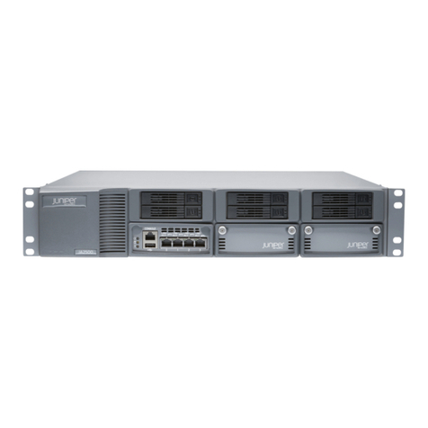
Juniper Networks Advanced Threat Prevenon 400 (JATP400) appliance is an advanced threat
prevenon plaorm that is designed to idenfy and prevent targeted aacks across mulple threat
vectors. The appliance can be deployed as a Core device, Trac Collector, Email Collector, Manager of
Central Managers (MCM), Secondary Core, or as an All-In-One device.
The JATP400 appliance is a 1-rack-unit (1-U), rack-mountable chassis with hot-swappable dual AC
power supplies (or oponal dual DC power supplies), four hot-swappable hard disk drives that support
RAID, 32-GB memory, two 10-Gigabit Ethernet interfaces, two 10-Gigabit Ethernet SFP+ interfaces, and
four 1-Gigabit Ethernet interfaces.
Benets of the JATP400 Appliance
•Mulvector trac inspecon—Provides connuous, mulstage detecon and analysis of Web, e-
mail, and lateral spread trac moving through the network.
•Mulstage threat detecon—Monitors network trac to idenfy threats as they progress through
the kill chain, detecng phishing, exploits, malware downloads, command and control
communicaons, and internal threats.
2

•Mulstage threat analysis—Performs stac, payload, machine learning, and behavior analyses, as well
as malware reputaon analysis, and connuously adapts to the changing threat landscape by
leveraging Juniper Networks Global Security Service, a cloud-based service that oers the latest
threat detecon and migaon informaon.
•Threat analycs—Oers a holisc view of identy and threat acvity gathered from a diverse set of
sources such as Acve Directory, endpoint anvirus, rewalls, secure Web gateways, intrusion
detecon systems, and endpoint detecon and response tools. The analycs component receives
data from these sources, idenes advanced malicious traits, and correlates the events to provide
complete visibility into a threat’s kill chain.
•Integraon with third-party devices—The JATP400 appliance supports an open API architecture,
which enables it to integrate with several third-party security devices to seamlessly and
automacally migate threats.
JATP400 Appliance Transceiver Interface
Two 10-Gigabit Ethernet SFP+ ports on the rear panel of the JATP400 appliance support SFP+
transceivers. Table 1 on page 3 lists the details of supported transceiver type.
Table 1: JATP400 Appliance Transceiver Type
Transceiver Type Card Model Descripon
SFP+ UNIV-SFPP-DUAL-SR Dual Rate 10GBASE-SR/1000BASE-SX
UNIV-SFPP-DUAL-LR Dual Rate 10GBASE-LR/1000BASE-LX
JATP400 Field-Replaceable Units
Field-replaceable units (FRUs) are hardware components that can be replaced at the customer site. Hot-
swappable FRUs are the components that you can remove and replace without powering o the device
or disrupng the funcons of the device.
JATP400 appliance supports FRUs: power supply and hard disk drive.
3
RELATED DOCUMENTATION
JATP400 Chassis | 4
Overview of Preparing the Site for the JATP400 | 17
JATP400 Installaon Overview | 25
JATP400 Chassis
IN THIS SECTION
JATP400 Appliance Front Panel Descripon | 4
JATP400 Appliance Back Panel Descripon | 10
JATP400 Appliance Front Panel Descripon
Figure 1 on page 4 shows the front panel components of the JATP400 appliance.
Figure 1: JATP400 Front Panel
Table 2 on page 5 lists the front panel components of the JATP400 appliance.
4

Table 2: JATP400 Front Panel Components
Callout Component Descripon
1 Front Bezel Protects the appliance.
2 Lock Locks the appliance.
3 Chassis LEDs Provides the colors and states, and
the status they indicate.
4 RESET buon Reboots the appliance.
5 Power buon Powers on or powers o the
appliance.
Use the main power buon to apply
or remove power from the power
supply to the server. Turning o
system power with this buon
removes the main power but
maintains standby power. To
perform many maintenance tasks,
you must also unplug system before
servicing.
6 Hard drive Four 2-TB hard disk drives.
5

Figure 2 on page 6 shows the front panel LEDs of the JATP400 appliance.
Figure 2: JATP400 Front Panel LEDs
Table 3 on page 6 lists the front panel LEDs of the JATP400 appliance.
Table 3: JATP400 Front Panel LEDs
Callout LEDs Descripon
1 UID Depressing the UID (unit idener)
buon illuminates an LED on both
the front and rear of the chassis for
easy system locaon in large stack
conguraons. The LED will remain
on unl the buon is pushed a
second me.
6

Table 3: JATP400 Front Panel LEDs
(Connued)
Callout LEDs Descripon
2Informaon • Solid red—Indicates an overheat
condion, which might be
caused due to cable congeson.
TIP: Check the roung of the
cables if they are obstrucng the
airow from the system.
• Red (blinking)—Indicates a fan
failure. Check for an inoperave
fan.
• Red (slowly blinking)—Indicates a
power failure. That is, the power
is received but the power supply
is not funconing. Check for a
non-operaonal power supply.
• Solid blue —Indicates local User
ID (UID) funcon is acvated.
Use this funcon to locate the
server in a rack mount
environment.
• Blue (blinking)—Indicates Remote
UID is on. Use this funcon to
idenfy that the server is used
from a remote locaon.
3GLAN2 • Flashing—Indicates network
acvity on LAN port 2.
• Steady—Indicates link.
7

Table 3: JATP400 Front Panel LEDs
(Connued)
Callout LEDs Descripon
4 GLAN1 • Flashing—Indicates network
acvity on LAN port 1.
• Steady—Indicates link.
5 Hard drive Indicates acvity on a hard drive
when flashing.
6 Power For AC power supply:
• Solid green—Indicates that the
appliance is receiving power.
• Solid amber—Indicates that the
power supply is plugged in and
turned o, or the system is o
but in an abnormal state.
For DC power supply:
• Solid green—Indicates that the
appliance is receiving power.
• Solid amber—Indicates that the
power supply is plugged in and
turned o, or the system is o
but in an abnormal state.
• Amber (blinking)—Indicates that
the system power supply
temperature has reached 63° C.
NOTE: The system powers down
automacally when the power
supply temperature reaches 70°
C and restarts when the power
supply temperature goes below
60° C.
8

Table 4 on page 9 lists the JATP400 hard disk drive port LEDs.
Table 4: JATP400 HDD Port LEDs
LEDs Descripon
Acvity (top) • Solid green—Indicates that the SAS drive is
installed.
• Green (blinking)—Indicates the I/O acvity.
Status (boom) • Solid red—Indicates failed drive for Serial Aached
SCSI (SAS), Serial Advanced Technology Aachment
(SATA), or Non-volale memory express (NVMe)
with Rapid Storage Technology enterprise (RSTe)
support.
• Red (blinking):
• At 1 Hz—Indicates rebuild drive for SAS/SATA
with RSTe support.
• Two blinks and one stop at 1 Hz—Indicates hot
spare for SAS/SATA with RSTe support.
• On for ve seconds, then o—Indicates power
on for SAS/SATA with RSTe support.
• At 4 Hz—Indicates idenfy drive for SAS/SATA
with RSTe support.
• Solid green—Indicates that it is safe to remove
NVMe device.
• Amber (blinking at 1 Hz)—Indicates aenon state.
NOTE: Do not remove NVMe device.
9

JATP400 Appliance Back Panel Descripon
Figure 3 on page 10 shows the back panel components of the JATP400 appliance.
Figure 3: JATP400 Back Panel
Table 5 on page 10 lists the back panel components of the JATP400 appliance.
Table 5: JATP400 Back Panel Components
Callout Components Descripon
1 Power supply Provides power to all components.
2 USB port Port 1 of USB 2.0.
3 Dedicated IPMI LAN port One RJ-45 dedicated Intelligent
Plaorm Management Interface
(IPMI) LAN port.
4 USB port Port 7 of USB 3.0.
5 GLAN1 10-Gigabit Ethernet LAN port (eth6).
NOTE: This port is not supported.
6 GLAN2 10-Gigabit Ethernet LAN port (eth7).
NOTE: This port is not supported.
10

Table 5: JATP400 Back Panel Components
(Connued)
Callout Components Descripon
7 1-Gigabit Ethernet LAN port RJ-45 port, eth0, management
interface.
8 1-Gigabit Ethernet LAN port RJ-45 port, eth4.
eth1 when this port is used as 1-
Gigabit Ethernet copper port.
9 1-Gigabit Ethernet LAN port RJ-45 port, eth2, alternate exhaust
interface.
Use the alternate exhaust interface
for external connecvity in threat
detecon.
NOTE: You can congure alternate
exhaust interface only for Core or All-
In-One appliance.
10 1-Gigabit Ethernet LAN port RJ-45 port, eth3.
11 10-Gigabit Ethernet SFP+ port eth5.
NOTE: You can use this port as either
Fiber or Copper port based on type
of SFP used.
11

Table 5: JATP400 Back Panel Components
(Connued)
Callout Components Descripon
12 10-Gigabit Ethernet SFP+ port eth1. By default, this port is a 10-
Gigabit Ethernet ber monitoring
port.
NOTE: You can change this port to 1-
Gigabit Ethernet copper port for
trac monitoring through the
following command:
# set trac-monitoring-ifc 1gb_ifc
Aer you reboot the appliance, the
eth4 interface becomes the eth1
interface and this port becomes eth4.
13 VGA port One VGA port. Use this connecon
for VGA display.
14 USB port Port 8 of USB 3.0.
15 USB port Port 2 of USB 2.0.
16 COM port One DB-9 COM port.
NOTE: This port is not supported.
Figure 4 on page 12 shows the back panel 10-Gigabit Ethernet port LEDs of the JATP400 appliance.
Figure 4: JATP400 10-Gigabit Ethernet Port LEDs
12

Table 6 on page 13 lists the JATP400 10-Gigabit Ethernet port LEDs.
Table 6: JATP400 10-Gigabit Ethernet Port LEDs
Callout LEDs Descripon
1 Link • Green—Indicates that the speed of the
connecon is 10 Gbps.
• Amber—Indicates that the speed of the
connecon is 1 Gbps.
2Acvity • Green (blinking)—Indicates that there is
acvity on this port.
•O—Indicates no trac.
Figure 5 on page 13 shows the back panel 1-Gigabit Ethernet port LEDs of the JATP400 appliance.
Figure 5: JATP400 1-Gigabit Ethernet Port LEDs
Table 7 on page 13 lists the JATP400 1-Gigabit Ethernet port LEDs.
Table 7: JATP400 1-Gigabit Ethernet Port LEDs
Callout LEDs Descripon
1Acvity • Yellow (blinking)—Indicates that there is acvity on this port.
•O—Indicates no acvity.
13
Other manuals for JATP400
1
Table of contents
Other Juniper Chassis manuals

Juniper
Juniper Day One+ QFX5700 User manual

Juniper
Juniper CTP1000 Series Installation instructions

Juniper
Juniper CTP150 User manual

Juniper
Juniper MX960 User manual

Juniper
Juniper PTX10008 User manual

Juniper
Juniper Junos Space JA2500 Installation instructions

Juniper
Juniper PTX3000 Installation instructions

Juniper
Juniper Junos Space JA1500 User manual
Popular Chassis manuals by other brands

Hewlett Packard Enterprise
Hewlett Packard Enterprise Apollo 4510 Gen10 Setup and installation guide

Honeywell
Honeywell 2450Cm Series Quick installation guide

Advantech
Advantech IPC-602 manual

Supermicro
Supermicro SC213LTQ user manual

Jou Jye
Jou Jye NU-0528i Assembly instructions

Supermicro
Supermicro Supero SC809LT-780B user manual