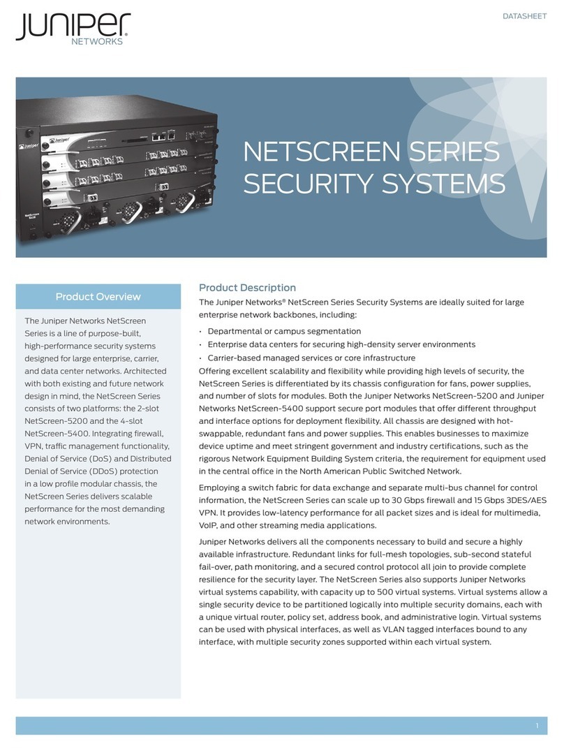
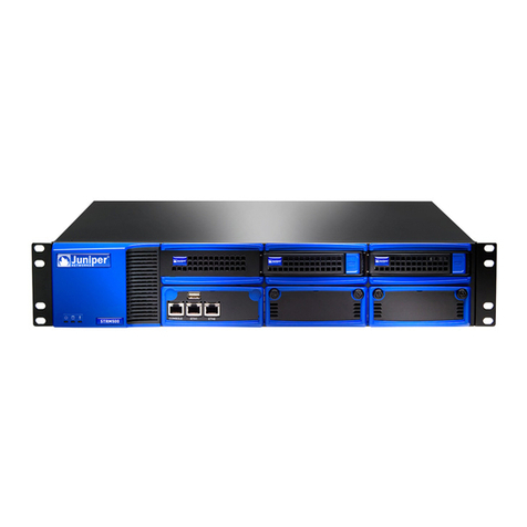
Juniper ISG 2000 User manual

Juniper Networks, Inc.
1194 North Mathilda Avenue
Sunnyvale, CA 94089
USA
408-745-2000
www.juniper.net
Part Number: 093-1524-000, Rev. A
ISG 2000
User’s Guide
ScreenOS 5.0.0-IDP1

ii
Copyright Notice
Copyright © 2005 Juniper Networks, Inc. All rights reserved.
Juniper Networks, the Juniper Networks logo, NetScreen, NetScreen Technologies, the NetScreen logo, NetScreen-Global Pro, ScreenOS, and GigaScreen
are registered trademarks of Juniper Networks, Inc. in the United States and other countries.
The following are trademarks of Juniper Networks, Inc.: Deep Inspection, ERX, ESP, Instant Virtual Extranet, Internet Processor, J-Protect, JUNOS,
JUNOScope, JUNOScript, JUNOSe, M5, M7i, M10, M10i, M20, M40, M40e, M160, M320, M-series, MMD, NetScreen-5GT, NetScreen-5XP,
NetScreen-5XT, NetScreen-25, NetScreen-50, NetScreen-100, NetScreen-204, NetScreen-208, NetScreen-500, NetScreen-5200, NetScreen-5400,
NetScreen-IDP 10, NetScreen-IDP 100, NetScreen-IDP 500, NetScreen-IDP 1000, IDP 50, IDP 200, IDP 600, IDP 1100, ISG 1000, ISG 2000,
NetScreen-Global Pro Express, NetScreen-Remote Security Client, NetScreen-Remote VPN Client, NetScreen-SA 1000 Series, NetScreen-SA 3000 Series,
NetScreen-SA 5000 Series, NetScreen-SA Central Manager, NetScreen Secure Access, NetScreen-SM 3000, NetScreen-Security Manager,
GigaScreen ASIC, GigaScreen-II ASIC, NMC-RX, SDX, Stateful Signature, T320, T640, and T-series.
Information in this document is subject to change without notice.
No part of this document may be reproduced or transmitted in any form or by any means, electronic or mechanical, for any purpose, without receiving
written permission from:
Juniper Networks, Inc.
ATTN: General Counsel
1194 N. Mathilda Ave.
Sunnyvale, CA 94089
FCC Statement
The following information is for FCC compliance of Class A devices: This equipment has been tested and found to comply with the limits for a Class A
digital device, pursuant to part 15 of the FCC rules. These limits are designed to provide reasonable protection against harmful interference when the
equipment is operated in a commercial environment. The equipment generates, uses, and can radiate radio-frequency energy and, if not installed and
used in accordance with the instruction manual, may cause harmful interference to radio communications. Operation of this equipment in a residential
area is likely to cause harmful interference, in which case users will be required to correct the interference at their own expense.
The following information is for FCC compliance of Class B devices: The equipment described in this manual generates and may radiate radio-frequency
energy. If it is not installed in accordance with NetScreen’s installation instructions, it may cause interference with radio and television reception. This
equipment has been tested and found to comply with the limits for a Class B digital device in accordance with the specifications in part 15 of the FCC
rules. These specifications are designed to provide reasonable protection against such interference in a residential installation. However, there is no
guarantee that interference will not occur in a particular installation.
If this equipment does cause harmful interference to radio or television reception, which can be determined by turning the equipment off and on, the user
is encouraged to try to correct the interference by one or more of the following measures:
Reorient or relocate the receiving antenna.
Increase the separation between the equipment and receiver.
Consult the dealer or an experienced radio/TV technician for help.
Connect the equipment to an outlet on a circuit different from that to which the receiver is connected.
Caution: Changes or modifications to this product could void the user's warranty and authority to operate this device.
Disclaimer
THE SOFTWARE LICENSE AND LIMITED WARRANTY FOR THE ACCOMPANYING PRODUCT ARE SET FORTH IN THE INFORMATION PACKET THAT SHIPPED
WITH THE PRODUCT AND ARE INCORPORATED HEREIN BY THIS REFERENCE. IF YOU ARE UNABLE TO LOCATE THE SOFTWARE LICENSE OR LIMITED
WARRANTY, CONTACT YOUR JUNIPER NETWORKS REPRESENTATIVE FOR A COPY.

Table of Contents iii
Table of Contents
About This Guide v
Content Summary........................................................................................... vi
CLI Conventions.............................................................................................. vi
Terminology................................................................................................... vii
IDP Requirements and Documentation......................................................... viii
ISG 2000 Upgrade .................................................................................. viii
IDP Configuration through NetScreen-Security Manager......................... viii
NetScreen Product Documentation Guide ....................................................... ix
Technical Support ............................................................................................ x
Chapter 1 Configuring 1
Before Beginning..............................................................................................2
Console Connection and Login.........................................................................3
Basic Configuration ..........................................................................................4
System Clock and Console Timeout .................................................................5
Admin Name and Password.............................................................................5
Security Zones and Interfaces ..........................................................................6
Binding Interfaces to Zones .......................................................................8
Interface Modes.........................................................................................9
Configuring Interfaces .............................................................................10
Untrust Zone Interface ......................................................................10
DMZ Interface ...................................................................................11
Trust Zone Interface..........................................................................11
MGT Interface ...................................................................................11
DNS and Default Route ..................................................................................12
Policies...........................................................................................................13
Addresses ................................................................................................13
Services ...................................................................................................13
Intrusion Detection and Protection ................................................................15
Minimum Configuration for a NetScreen-Security Manager
Connection .......................................................................................15
IPSec VPN ......................................................................................................16
ISG 2000 ...........................................................................................17
Remote Peer .....................................................................................18
Summary of CLI Commands ..........................................................................19
CLI Commands – Example Firewall Configuration...................................19
CLI Commands – Example Route-Based VPN Configuration....................20
Returning the Device to Factory Default Settings ...........................................21

iv Table of Contents
ISG 2000 User’s Guide
Chapter 2 Installing 23
Connecting the Device to a Network ..............................................................24
Equipment Rack Mounting.............................................................................26
Equipment Rack Installation Guidelines...................................................26
Equipment Rack Accessories and Required Tools....................................26
Rear-and-Front Mount .............................................................................27
Mid-Mount ...............................................................................................28
Chapter 3 Hardware and Servicing 29
The Front Panel .............................................................................................30
LED Dashboard .......................................................................................32
The Rear Panel...............................................................................................33
Replacing Interface Modules ..........................................................................33
Removing Interface Modules ...................................................................34
Inserting Interface Modules .....................................................................35
Connecting and Disconnecting Gigabit Ethernet Cables .................................36
Replacing a Mini-GBIC Transceiver.................................................................38
Replacing Power Supplies ..............................................................................39
Replacing AC Power Supplies ..................................................................39
Replacing DC Power Supplies ..................................................................41
Replacing the Fan Tray ..................................................................................44
Replacing the Fan Tray Filter...................................................................45
Appendix A Specifications 47
ISG 2000 Attributes........................................................................................47
Electrical Specifications..................................................................................47
Environmental Specifications.........................................................................48
NEBS Certifications ........................................................................................48
Safety Certifications .......................................................................................48
EMI Certifications...........................................................................................48
Connectors.....................................................................................................49
Index.......................................................................................................................... 51

v
About This Guide
This guide describes how to install, configure, and service the ISG 2000. It presents
an example of a basic installation and configuration that secures resources in the
Trust and DMZ security zones, sets up a MGT zone for device administrators, and
defines a route-based VPN tunnel between the ISG 2000 and a remote peer (see
Figure 1). You can use this example as a reference as you perform similar tasks.
Figure 1: Example Configuration
This guide makes the following assumptions:
You are adding the ISG 2000 to an existing network.
You have an account with an Internet service provider (ISP) that has provided
you with two sets of IP addresses:
An outside address in the ISP’s domain (1.1.1.1 in our example)
A range of addresses in your domain (such as 1.2.2.1–1.2.2.6)
You have a registered domain name (such as “jnpr.net”).
NOTE: Intrusion Detection and Prevention (IDP) requires the installation of at least one
security module, an advanced license key, and an IDP license key. To configure
IDP on the ISG 2000, you must use NetScreen-Security Manager.
HA
FLASH
PWR
FAN
ALARM
MOD1
TEMP
MOD2
STATUS
MOD3 ISG 2000
®
POWER STATUS
1 2 3 4
LINK/ACTIVITY
10/100
UNTRUSTED
DMZ
ISP
Untrust Zone
Internet
LAN
10.2.2.0/24
VPN
Tunnel
Policies
ethernet1/1
1.1.1.1/30
ethernet2/1
10.1.1.1/24
NAT mode
LAN
10.1.1.0/24
Trust Zone
MGT Zone
10.2.2.0/28
ethernet1/2
1.2.2.1/29
LAN
1.2.2.0/29
HTTP Server
www.jnpr.net
1.2.2.2:80
Mail Relay Server
smtp.jnpr.net
1.2.2.3:25
Remote Peer
ISP
Default GW: 1.1.1.2
DNS #1: 2.2.2.5
DNS #2: 2.2.2.6
MGT
10.2.2.1/28
Note: The rook icon represents
a security zone interface.

ISG 2000 User’s Guide
vi Content Summary
Content Summary
This guide contains the following chapters and appendix:
Chapter 1, “Configuring” provides instructions for making a console connection
to the ISG 2000, logging in, and performing a basic yet complete firewall and
VPN configuration.
Chapter 2, “Installing” provides instructions for cabling the ISG 2000 to the
network, mounting the device in a rack, and connecting the power supplies.
Chapter 3, “Hardware and Servicing” provides a detailed overview of the ISG
2000 and procedures for replacing interface modules, power supplies, and the
fan tray.
Appendix A, “Specifications” provides a list of physical specifications about the
ISG 2000, its modules, and its power supplies.
CLI Conventions
The following conventions are used when presenting the syntax of a command line
interface (CLI) command:
Anything inside square brackets [ ] is optional.
Anything inside braces { } is required.
If there is more than one choice, each choice is separated by a pipe ( | ). For
example,
set interface { ethernet1/1 | ethernet1/2 | ethernet2/1 } manage
means “set the management options for the ethernet1/1, ethernet1/2, or
ethernet2/1 interface”.
Variables appear in italic. For example:
set admin user name_str password pswd_str
When a CLI command appears within the context of a sentence, it is in bold
(except for variables, which are always in italic). For example: “Use the get
system command to display the serial number of a NetScreen device.”
NOTE: When typing a keyword, you only have to type enough letters to identify the word
uniquely. For example, typing set adm u joe p j12fmt54 is enough to enter the
command set admin user joe password j12fmt54. Although you can use this
shortcut when entering commands, all the commands documented here are
presented in their entirety.

Terminology vii
:
Terminology
The following list contains acronyms and terminology used throughout this guide:
CLI command line interface, a tool for configuring ScreenOS through a
console, Telnet, or secure shell (SSH) connection
DMZ demilitarized zone, a predefined security zone for resources such as
Web servers to which you allow access from unknown hosts
function zone a conceptual location for interfaces providing specific functionality,
such as device management access or high availability (HA) links
Global zone a security zone without an interface that acts as a virtual storage
space for mapped IP (MIP) and virtual IP (VIP) addresses
hot swappable able to be recognized by a system when connected and disconnected
without having to turn off and on the system
IDP Intrusion Detection and Prevention, a technology for performing
deep packet inspection and taking preventive action
IKE Internet Key Exchange, a protocol for securely yet publicly
negotiating keys to authenticate and encrypt/decrypt traffic
IPSec Internet Protocol Security, a suite of related protocols for
cryptographically securing communications at the IP packet layer
license key a key (in the form of an alphanumeric string) that unlocks features or
capacities within ScreenOS
MGT zone a function zone from which administrators can connect to the ISG
2000 exclusively for management purposes
mini-GBIC a gigabit interface converter that fits in a removable transceiver
NAT mode an operational mode for Layer 3 interfaces that translates the source
IP address of packets
NetScreen-Security
Manager
a management application that configures and monitors multiple
devices over a local or wide area network (LAN or WAN) environment
Null zone a virtual storage space for interfaces not bound to a zone
policy a rule that permits, denies, rejects, or tunnels specified types of
traffic unidirectionally between two points
route-based VPN tunnel a VPN tunnel bound to a tunnel interface to which a route points
Route mode an operational mode for Layer 3 interfaces that routes IP packets
through the ISG 2000 without modifying the packet header content
security zone a collection of one or more network segments requiring the
regulation of interzone and intrazone traffic through policies
ScreenOS the operating system of the ISG 2000
Transparent mode an operational mode for Layer 2 interfaces that forwards traffic like a
switch or bridge
Trust zone a predefined security zone for protected network resources to which
you typically do not allow access from unknown hosts
tunnel interface a logical interface that you bind to a route-based VPN tunnel
Untrust zone a predefined security zone for unknown network hosts typically in a
WAN such as the Internet
WebUI Web user interface, a graphical user interface for configuring
ScreenOS through a Web browser

ISG 2000 User’s Guide
viii IDP Requirements and Documentation
IDP Requirements and Documentation
You can upgrade the ISG 2000 to support Intrusion Detection and Prevention (IDP)
and then use NetScreen-Security Manager to configure IDP on the device.
ISG 2000 Upgrade
To run IDP on the ISG 2000, you must set up the device as follows:
Upgrade the OS loader to v.1.1.5 or later.
Load the following license keys and firmware:
Advanced license key
IDP license key
ScreenOS 5.0.0-IDP1
Install at least one security module.
To obtain the upgrade kit and security modules, contact your value added reseller
(VAR). For information about upgrading the ISG 2000 to support IDP, refer to the
ISG 2000 Field Upgrade Guide, which is included in the ISG 2000 upgrade kit.
IDP Configuration through NetScreen-Security Manager
To configure IDP on the ISG 2000, you must use NetScreen-Security Manager 2004
FP3r3 or later.
For information on configuring IDP on the ISG 2000 through NetScreen-Security
Manager, refer to the following documentation:
NetScreen-Security Manager 2004 FP3-IDPr1 Installer's Guide – Instructions on
installing NetScreen-Security Manager
ISG 2000 Getting Started with IDP Guide – General instructions to help you get
started configuring IDP with NetScreen-Security Manager
IDP Deployment Strategies – Advanced IDP implementation scenarios
NetScreen-Security Manager 2004 FP3-IDPr1 Administrator's Guide – Complete
reference guide for NetScreen-Security Manager
NetScreen-Security Manager Online Help – Step-by-step configuration details
complementing the information in the administrator’s guide
The NetScreen-Security Manager documentation is available on the Juniper
Networks Web site: www.juniper.net/techpubs.
NOTE: NetScreen-Security Manager 2004 FP3r3 can operate on Solaris 9, Red Hat Linux
9.0, and Red Hat Enterprise Linux 3.0 operating systems.

NetScreen Product Documentation Guide ix
:
NetScreen Product Documentation Guide
To obtain technical documentation for Juniper Networks NetScreen products, see
the product documentation CD-ROM that ships with the ISG 2000.
Figure 2: NetScreen Product Documentation CD-ROM
You can also get documentation for the following Juniper Networks technologies
and products by visiting www.juniper.net/techpubs/:
NetScreen-Security Manager
Security devices
ScreenOS
NetScreen-Remote VPN client
Intrusion Detection and Prevention (IDP)
Another resource is the WebUI Help. When logged in to the ISG 2000 through the
WebUI, click the Help button to learn more about ScreenOS features:
Figure 3: WebUI Help
If you find any errors or omissions in this guide, please contact us at
techpubs-comments@juniper.net, or complete and submit the documentation
feedback form at www.juniper.net/techpubs/docbug/docbugreport.html.
NetScreen Concepts & Examples ScreenOS Reference Guide
:
Extensive coverage of all major ScreenOS features, with
both conceptual background information and configuration
examples
NetScreenCLIReferenceGuide
: Compendium of all command
line reference (CLI) commands, with command syntax and
explanations of all keywords
NetScreen Messages Reference Guide
: Collection of the
messages that appear in the event log, with their meanings
and recommended actions
Getting Started Guides and User’s Guides
:
Platform-specific guides for connecting a
NetScreen device to a network and then
configuring it
Other Resources
:
• FIPS-certified and Common Criteria-certified images and
documentation
• Help files
• SNMP MIB files
• Dictionary file for external authentication servers
• NetScreen device installation steps
• More …
You can access context-sensitive Help by clicking the Help
button in the upper right corner of the WebUI …
… or by selecting Help > Online Help from the menu column.
The Help menu option also provides shortcuts to online
product registration and the NetScreen knowledgebase.

ISG 2000 User’s Guide
xTechnical Support
Technical Support
If you need any technical support, you can visit the Juniper Networks Customer
Support Center (CSC). There are many useful resources at the CSC, such as
A searchable knowledgebase containing solutions to over 2000 customer
questions
The latest ScreenOS firmware downloads
To have access to CSC resources, you must first create a customer account and
register your NetScreen product. To set up such an account, go to
www.juniper.net/entitlement/setupAccountInfo.do and follow the online
instructions.
After you have a customer account, you can create and submit technical support
cases for any product under warranty or with a valid support contract.
To open a support case, do the following:
1. Visit www.juniper.net/support.
2. In the Login to Support Center area, enter the user name and password that you
created while setting up your customer account.
3. Open a support case by clicking Case Management and then filling in the
online form. Include the output from the get tech and get license commands.
Also, if the network is complex, include a network diagram.
You can also open a support case by calling 1-888-314-JTAC (within the United
States) or 1-408-745-9500 (outside the United States).
NOTE: Release Notes are part of a firmware download.
NOTE: You need the serial number of the ISG 2000 to complete the account setup and
device registration.

1
Chapter 1
Configuring
This chapter describes how to make a console connection to the ISG 2000, log in,
and perform a basic configuration.
This chapter includes the following main configuration sections:
“Before Beginning” on page 2
“Console Connection and Login” on page 3
“Basic Configuration” on page 4
“System Clock and Console Timeout” on page 5
“Admin Name and Password” on page 5
“Security Zones and Interfaces” on page 6
“DNS and Default Route” on page 12
“Policies” on page 13
“Intrusion Detection and Protection” on page 15
“IPSec VPN” on page 16
“Summary of CLI Commands” on page 19
“Returning the Device to Factory Default Settings” on page 21
Table 1: Important Default Configuration Settings
Default MGT IP address: 192.168.1.1/24
Default ethernet IP addresses: 0.0.0.0/0
Default username: netscreen
Default password: netscreen
NOTE: You must register your product at
www.juniper.net/support/ so that you can
activate specific services, such as Intrusion Detection and Prevention (IDP).
After registering your product, purchase a license key from your value added
reseller (VAR), and then use NetScreen-Security Manager, the WebUI, or
the CLI to load the key. For information about registering your product and
obtaining and loading license keys, see the Fundamentals volume in the
NetScreen Concepts & Examples ScreenOS Reference Guide on the documentation
CD that ships with the ISG 2000.
NOTE: For information on different configuration options such as virtual systems and
high availability, see the NetScreen Concepts & Examples ScreenOS Reference Guide.

ISG 2000 User’s Guide
2Before Beginning
Before Beginning
Before setting up the ISG 2000, you must make a few preparations.
1. Consider the network topology and the resources that you want to protect so
that you can decide where to put the ISG 2000. You want to make sure that all
traffic on which you want to enforce policies flows through the device. (A typical
network topology showing where to put the ISG 2000 is shown in Figure 1 on
page v, and on Figure 5 on page 4.)
2. Plan out the IP addresses and—where applicable—host.domain names that you
want each host to use. The devices in this guide use the following addresses:
ISG 2000
Untrust zone interface (ethernet1/1): 1.1.1.1/30
DMZ zone interface (ethernet1/2): 1.2.2.1/29
Trust zone interface (ethernet2/1): 10.1.1.1/24
MGT zone interface (MGT): 10.2.2.1/28
HTTP server: 1.2.2.2, www.jnpr.net
Mail relay server: 1.2.2.3, smtp.jnpr.net/pop3.jnpr.net
Trust zone hosts dynamically receive their addresses and DNS settings
from a stand alone DHCP server. Their default gateway is 10.1.1.1.
Network security administrators make an out-of-band connection to the
MGT interface on the ISG 2000. Their workstations are in the 10.2.2.0/28
subnet, completely separate from the rest of the network.
3. Obtain the IP addresses of the default gateway and external Domain Name
System (DNS) servers from the ISP. This guide uses the following addresses:
Default gateway: 1.1.1.2
Primary DNS server: 2.2.2.5
Secondary DNS server: 2.2.2.6
4. Communicate the IP addresses and host.domain names of the mail and web
servers to your ISP. After an ISP administrator adds this information to its DNS
servers, they can then answer DNS queries for them.
5. Ensure that the hosts in the Trust zone use 10.1.1.1 as their default gateway,
and that the servers in the DMZ use 1.2.2.1.
6. This guide assumes you configure the ISG 2000 through a console connection
from the serial port on your workstation to the console port on the ISG 2000.
You need the following:
VT100 terminal emulator such as Hilgraeve HyperTerminal installed on
your workstation (HyperTerminal is provided on all Windows operating
systems.)
The RJ-45 straight-through ethernet cable and DB9 adapter that ship with
the ISG 2000
Documentation CD that ships with the ISG 2000
For other device configuration methods, see the Administration volume in the
NetScreen Concepts & Examples ScreenOS Reference Guide.
NOTE: You must use NetScreen-Security Manager to configure Intrusion Detection and
Prevention (IDP) on the ISG 2000. See “Minimum Configuration for a
NetScreen-Security Manager Connection” on page 15.

Console Connection and Login 3
Chapter 1: Configuring
Console Connection and Login
To begin configuring the ISG 2000, make a console connection between your
workstation and the ISG 2000 and run a vt100 terminal emulator program.
1. Connect the power cable to the ISG 2000 and turn on the power.
2. Connect the female end of the supplied DB-9 adapter to the serial port (or Com
port) of your workstation.
3. Connect one end of the RJ-45 ethernet cable into the console port of the ISG
2000 and the other end of the cable to the DB-9 adapter.
Figure 4: Console Connection
4. Start a serial terminal emulation session. Use the following settings:
Baud Rate to 9600
Parity to No
Data Bits to 8
Stop Bit to 1
Flow Control to none
5. Press the Enter key to see the login prompt.
6. At the login prompt, enter netscreen
7. At the password prompt, enter netscreen
HA
FLASH
PWR
FAN
ALARM
MOD1
TEMP
MOD2
STATUS
MOD3 ISG 2000
Connect the Rj-45 ethernet
cable to the console port.
Rear of Workstation
Plug the DB-9 adapter into the serial port,
and then connect the ethernet cable to the adapter.
NOTE: The login (admin name) and password are both case-sensitive. To change the login
name and password, see “Admin Name and Password” on page 5.

ISG 2000 User’s Guide
4Basic Configuration
Basic Configuration
The following sections contain the CLI commands for setting up the ISG 2000 as a
firewall and VPN termination point for the network shown in Figure 5. By entering
these commands, you can perform a basic configuration of the ISG 2000 so that it
can perform firewall and VPN functions.
Figure 5: Basic Firewall and VPN Configuration
HA
FLASH
PWR
FAN
ALARM
MOD1
TEMP
MOD2
STATUS
MOD3 ISG 2000
®
POWER STATUS
1 2 3 4
LINK/ACTIVITY
10/100
UNTRUSTED
DMZ
ISP
Untrust Zone
Internet
LAN
10.2.2.0/24
VPN
Tunnel
Policies
ethernet1/1
1.1.1.1/30
ethernet2/1
10.1.1.1/24
NAT mode
LAN
10.1.1.0/24
Trust Zone
MGT Zone
10.2.2.0/28
ethernet1/2
1.2.2.1/29
LAN
1.2.2.0/29
HTTP Server
www.jnpr.net
1.2.2.2:80
Mail Relay Server
smtp.jnpr.net
1.2.2.3:25
Remote Peer
ISP
Default GW: 1.1.1.2
DNS #1: 2.2.2.5
DNS #2: 2.2.2.6
MGT
10.2.2.1/28
The NetScreen-ISG 2000 permits
selected traffic between zones.
A route-based VPN tunnel provides
secure bidirectional traffic between
the NetScreen-ISG 2000 and a remote peer.
Note:
The rook icon represents
a security zone interface.

System Clock and Console Timeout 5
Chapter 1: Configuring
System Clock and Console Timeout
You need to set the system clock so that the event log entries have the correct
date/time stamps. Also, the correct date/time is essential if the device has to check
the validity of digital certificates.
You can also change the timeout value for an idle console connection. By default,
the ISG 2000 automatically closes a console connection if it is idle for 10 minutes.
You can change this to a higher or lower interval, or disable the timeout completely.
1. Set the system clock with the following command:
set clock dd/mm/yyyy hh:mm:ss
where dd/mm/yyyy = day/month/year, and hh:mm:ss = hour/minute/second
(for example: 07/15/2005 16:40:55).
save
After you enter the save command, the ISG 2000 saves the current
configuration to flash memory. If you reset the device without saving the latest
configuration, the ISG 2000 loads the previously saved configuration.
2. (Optional) By default, the console times out and terminates automatically after
10 minutes of idle time. To change this timeout interval, enter the following:
set console timeout number
save
where number is the length of idle time in minutes before session termination.
To prevent any automatic termination, specify a value of 0. This setting is
convenient for performing an initial configuration, but Juniper Networks does
not recommend permanently disabling the console timeout.
Admin Name and Password
Because all NetScreen products use the same admin name and password
(netscreen), it is highly advisable to change your login information immediately. To
change your login information, enter the following commands:
set admin name name_str
set admin password pswd_str
save
NOTE: To see other options for setting the system clock, refer to the Fundamentals
volume in the NetScreen Concepts & Examples ScreenOS Reference Guide.
NOTE: For information on creating multiple administrators with different administrative
levels, refer to the Administration volume in the NetScreen Concepts & Examples
ScreenOS Reference Guide.
If you want to return the ISG 2000 to its default configuration (including the default
login name and password), see “Returning the Device to Factory Default Settings”
on page 21.

ISG 2000 User’s Guide
6Security Zones and Interfaces
Security Zones and Interfaces
A security zone is a collection of one or more network segments requiring the
regulation of inbound and outbound traffic through policies. You use security zones
to separate network segments of differing trust levels and control the flow of traffic
between them by the policies that you set.
Figure 6: Three Security Zones
The ISG 2000 ships with seven predefined security zones—including the Global
zone, which is used mainly for holding mapped IP (MIP) and virtual IP (VIP)
addresses. For information on all zone types and their uses, see the Fundamentals
volume in the NetScreen Concepts & Examples ScreenOS Reference Guide.
To view all the predefined zones, enter the get zone command, as shown below.
get zone
Total 13 zones created in vsys Root - 7 are policy configurable.
Total policy configurable zones for Root is 7.
ID Name Type Attr VR Default-IF VSYS
0 Null Null Shared untrust-vr hidden Root
1 Untrust Sec(L3) Shared trust-vr null Root
2 Trust Sec(L3) trust-vr null Root
3 DMZ Sec(L3) trust-vr null Root
4 Self Func trust-vr self Root
5 MGT Func trust-vr mgt Root
6 HA Func trust-vr null Root
10 Global Sec(L3) trust-vr null Root
11 V1-Untrust Sec(L2) trust-vr v1-untrust Root
12 V1-Trust Sec(L2) trust-vr v1-trust Root
13 V1-DMZ Sec(L2) trust-vr v1-dmz Root
14 VLAN Func trust-vr vlan1 Root
16 Untrust-Tun Tun trust-vr hidden.1 Root
HA
FLASH
PWR
FAN
ALARM
MOD1
TEMP
MOD2
STATUS
MOD3 ISG 2000
Policies
Security Zone
Security Zone
Security Zone
Three security zones requiring interzone policies
for traffic to flow from one zone to another.
The security zones can be Layer 3
zones or Layer 2 zones.

Security Zones and Interfaces 7
Chapter 1: Configuring
There are three predefined security zones for interfaces operating at the Network
Layer (Layer 3) in the Open Systems Interconnection (OSI) Model and three
predefined security zones for interfaces operating at the Data Link Layer (Layer 2):
Predefined Layer 3 security zones: Untrust, Trust, and DMZ
Predefined Layer 2 security zones: V1-Untrust, V1-Trust, and V1-DMZ
The example in this guide uses the three predefined Layer 3 security zones.
Figure 7: Untrust, DMZ, and Untrust Security Zones
You can define more security zones by using the following command:
set zone name zone [ l2 id_num ]
For information on creating zones, see the chapter on zones in the Fundamentals
volume in the NetScreen Concepts & Examples ScreenOS Reference Guide.
HA
FLASH
PWR
FAN
ALARM
MOD1
TEMP
MOD2
STATUS
MOD3 ISG 2000
Untrust Zone
DMZ Zone
Trust Zone
Note: This illustration shows the typical uses of each zone. However, this arrangement is
not compulsory. You can customize their uses to best suit your network environment.
This zone typically contains the public
network that the NetScreen-ISG 2000
protects against.
This zone typically contains
your public-facing resources,
such as web servers.
This zone typically contains your
protected internal resources.

ISG 2000 User’s Guide
8Security Zones and Interfaces
Binding Interfaces to Zones
The ISG 2000 supports different types of interface modules in four interface module
bays. The leftmost interface in the module in the upper left bay is ethernet1/1. The
interface to the right of ethernet1/1 is ethernet1/2. If there are more interfaces in
that module, they are numbered ethernet1/3, ethernet1/4, and so on. As you can
see, the first number represents the position of the interface module in one of the
four bays, and the second number represents the position of the interface in that
module from left to right.
Figure 8: Interface Numbers
As you can see in the output from the get interface command below, none of the
interface module interfaces are prebound to a security zone. They are all in the Null
zone.
get interface
A - Active, I - Inactive, U - Up, D - Down, R - Ready
Interfaces in vsys Root:
Name IP Address Zone MAC VLAN State VSD
mgt 192.168.1.1/24 MGT 0010.db58.bb80 – D –
eth1/1 0.0.0.0/0 Null 0010.db58.bb87 – D –
eth1/2 0.0.0.0/0 Null 0010.db58.bb88 – D –
eth1/3 0.0.0.0/0 Null 0010.db58.bb89 – D –
eth1/4 0.0.0.0/0 Null 0010.db58.bb8a – D –
eth2/1 0.0.0.0/0 Null 0010.db58.bb9d – D –
eth2/2 0.0.0.0/0 Null 0010.db58.bb9e – D –
eth3/1 0.0.0.0/0 Null 0010.db58.bb8d – D –
eth3/2 0.0.0.0/0 Null 0010.db58.bb8e – D –
eth4/1 0.0.0.0/0 Null 0010.db58.bb81 – D –
eth4/2 0.0.0.0/0 Null 0010.db58.bb82 – D –
eth4/3 0.0.0.0/0 Null 0010.db58.bb83 – D –
eth4/4 0.0.0.0/0 Null 0010.db58.bb84 – D –
vlan1 0.0.0.0/0 VLAN 0010.db58.bb8f 1 D –
13
24
Interface Module Bays
e1/1 e1/2 e1/3 e1/4
e4/1 e4/2 e4/3 e4/4
e3/1 e3/2
e2/1 e2/2

Security Zones and Interfaces 9
Chapter 1: Configuring
Before you can make use of an interface, you must bind it to a security zone. The
interface then becomes a point of ingress and egress for traffic to and from that
zone. You can bind a single interface to only one security zone, although that one
zone can support multiple different interfaces. To bind an interface to a zone, use
the following command:
set interface interface zone zone
in which interface and zone are the names of the objects you want to bind together.
For example:
set interface ethernet1/1 zone untrust
set interface ethernet1/2 zone dmz
set interface ethernet2/1 zone trust
save
Figure 9: Interfaces Bound to Security Zones
Interface Modes
An ISG 2000 security zone interface can operate in one of three modes: NAT mode,
Route mode, or Transparent mode. NAT mode and Route mode operate at the
Network Layer (Layer 3) in the OSI Model. Transparent mode operates at the Data
Link Layer (Layer 2). Although some interfaces can function in NAT mode while
others concurrently function in Route mode—both modes operating at Layer 3—
the ISG 2000 does not support different interfaces operating concurrently at Layer 3
and Layer 2.
Layer 3 (Route mode and NAT mode) – When you bind an interface to a Layer 3
security zone and give it an IP address, it can operate in either NAT or Route mode.
When an interface is in NAT mode, the NetScreen device translates the source IP
address and source port number on all packets arriving at that interface. When an
interface is in Route mode, the NetScreen device performs Layer 3 routing
operations without modifying the source IP address or port number.
NOTE: The interface names that appear in the get interface output depend on the type
of interface modules installed in the ISG 2000. Most likely the output you see
differs from that shown here.
HA
FLASH
PWR
FAN
ALARM
MOD1
TEMP
MOD2
STATUS
MOD3 ISG 2000
Untrust Zone
DMZ Zone
Trust Zone
ethernet1/2
ethernet1/1
ethernet2/1 Note:
The rook icon represents
a security zone interface.

ISG 2000 User’s Guide
10 Security Zones and Interfaces
When you bind an interface to a Layer 2 security zone, it does not have an IP
address and operates in Transparent mode. The NetScreen device forwards traffic
arriving at an interface in Transparent mode essentially like a Layer 2 bridge. That
is, the NetScreen device uses the MAC address in the Layer 2 header to forward
traffic out onto another segment in the same broadcast domain.
By default, no ISG 2000 security zone interfaces have IP addresses and all are in the
Null zone. The Null zone is a function zone that holds interfaces until you bind them
to a security zone. To make a security zone interface operational, you must bind it
to a security zone and, if it is a Layer 3 security zone, assign it an IP address.
Configuring Interfaces
After you bind an interface to a security zone, you can assign it an IP address. and
configure other settings for that interface. To assign an IP address to an interface,
use the following command:
set interface interface ip ip_addr/netmask
where interface is the name of the interface, and ip_addr/netmask is the IP address
and netmask that you assign it.
To set management options on an interface, use the following command:
set interface
interface
manage
[
ident-reset
|
ping
|
snmp
|
ssh
|
ssl
|
telnet
|
web
]
in which you can specify one or none of the options following the keyword
manage. If you enter just set interface interface manage, the command enables all
the interface options except ident-reset. If you want to enable a subset of all the
options, you can repeatedly enter the command, each time specifying a different
management option.
Untrust Zone Interface
In our example, ethernet1/1 is bound to the Untrust zone. The ISP provided the
address for this interface: 1.1.1.1/30. Because this interface is going to face
unknown and potentially malicious entities in the public network, you do not
enable any management options on this interface.
set interface ethernet1/1 ip 1.1.1.1/30
save
To review the settings for ethernet1/1, enter the following command:
get interface ethernet1/1
This command produces the following output:
Interface ethernet1/1:
number 7, if_info 57400, if_index 0, mode route
link up, phy-link up/full-duplex
NOTE: For more information about interface modes, see the chapter on interface modes
in the Fundamentals volume in the NetScreen Concepts & Examples ScreenOS
Reference Guide.
Table of contents
Other Juniper Security System manuals
Popular Security System manuals by other brands

EDS
EDS EDA-T Series installation manual

Cisco
Cisco ASA 5506W-X Hardware installation guide

Klaxon
Klaxon Super M installation instructions

brennenstuhl
brennenstuhl BrematicPRO THS 868 01 IP44 Instructions for use

SafeNet
SafeNet eSafe XG-210 quick start guide

Felsenmeer
Felsenmeer SHALOSH ECO operating instructions