manuals.online logo
Brands
  1. Home
  2. •
  3. Brands
  4. •
  5. Juniper
  6. •
  7. Switch
  8. •
  9. Juniper EX Series User manual

Juniper EX Series User manual

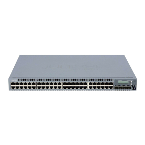
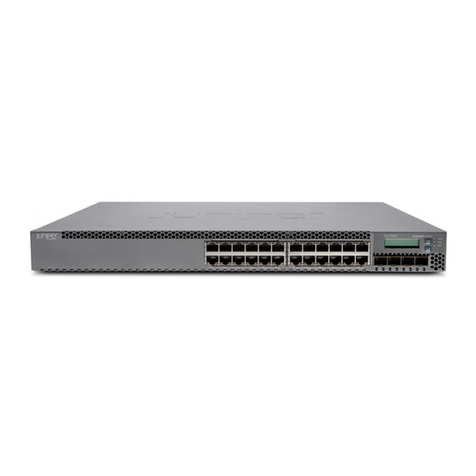
EX3400 Switch Quick Start
See the complete EX Series documentation at
http://www.juniper.net/documentation/.
To mount the Juniper Networks EX3400 Ethernet Switch on
two posts of a rack, you need:
zTwo mounting brackets and eight mounting screws
(provided)
zScrews to secure the chassis to the rack (not provided)
zPhillips (+) screwdriver, number 2 (not provided)
To connect the switch to earth ground, you need:
zA grounding cable (minimum 14 AWG (2 mm²), minimum
90°C wire), a grounding lug (Panduit LCC10-14BWL or
equivalent), a pair of 10-32x0.25-in. screws with #10
split-lock washer, and a pair of #10 flat washers—none provided
To connect power to the switch, you need:
zPower cord with a plug appropriate for your geographical location (provided) and a
power cord retainer strip (provided)
To perform initial configuration of the switch, you need:
zEthernet cable with an RJ-45 connector attached (provided)
zRJ-45 to DB-9 serial port adapter (provided)
zManagement host, such as a laptop or PC, with an Ethernet port (not provided)
Register product serial numbers on the Juniper Networks website and update the
installation base data if there is any addition or change to the installation base or if the
installation base is moved. Juniper Networks will not be held accountable for not meeting
the hardware replacement service-level agreement for products that do not have
registered serial numbers or accurate installation base data.
Register your product(s) at https://tools.juniper.net/svcreg/SRegSerialNum.jsp.
Update your install base at
https://www.juniper.net/customers/csc/management/updateinstallbase.jsp.
The fan modules and the power supplies in EX3400 switches are hot-removable and
hot-insertable field-replaceable units (FRU): You can remove and replace them without
powering off the switch or disrupting switch functions.
CAUTION:
Do not mix power supplies and fan modules with different airflow labels (AIR IN
(AFI) and AIR OUT (AFO)) in the same chassis.
WARNING: Ensure that you understand how to prevent electrostatic discharge
(ESD) damage. Attach the ESD grounding strap to your bare wrist, and connect the
strap to the ESD point on the chassis.
Part 1: Mount the Switch on Two Posts of a Rack
You can mount an EX3400 switch on a desk or a level surface, on two or four posts of a
rack or cabinet, or on a wall. This guide describes the procedure to mount the switch on
two posts of a rack.
Two persons are required for this procedure.
1. Place the rack in its permanent location, allowing adequate clearance for airflow and
maintenance, and secure it to the building structure.
NOTE: When you mount multiple units on a rack, mount the heaviest unit at the bottom
and mount the other units from bottom to top in decreasing order of weight.
2. Align the mounting brackets along the front of the side panels of the chassis.
3. Attach the brackets to the chassis by using the mounting screws. Tighten the screws.
4. Have one person grasp both sides of the switch, lift the switch, and position it in the
rack, aligning the mounting bracket holes with the threaded holes in the rack rail.
Align the bottom hole in each mounting bracket with a hole in each rail, making sure
that the chassis is level.
5. Have the second person secure the switch to the rack by using the appropriate
screws. Tighten the screws.
Part 2: Connect Power to the Switch
NOTE: We recommend that you connect DC or AC-powered systems to earth ground.
The power cord inlet and earthing terminal are on the rear panel of the switch.
1. Secure the grounding lug over the earthing terminal on the rear panel by using
washers and screws.
2. Push the end of the retainer strip into the slot above the power cord inlet until the strip
snaps into place. Ensure that the loop in the retainer strip faces toward the power
cord.
g022238
Juniper Networks, Junos, Steel-Belted Radius, NetScreen, and ScreenOS are registered trademarks of Juniper Networks, Inc. in the United States and other countries. The Juniper Networks Logo, the Junos logo, and JunosE are
trademarks of Juniper Networks, Inc. All other trademarks, service marks, registered trademarks, or registered service marks are the property of their respective owners. Juniper Networks assumes no responsibility for any inaccuracies
in this document. Juniper Networks reserves the right to change, modify, transfer, or otherwise revise this publication without notice. Products made or sold by Juniper Networks or components thereof might be covered by one or more
of the following patents that are owned by or licensed to Juniper Networks: U.S. Patent Nos. 5,473,599, 5,905,725, 5,909,440, 6,192,051, 6,333,650, 6,359,479, 6,406,312, 6,429,706, 6,459,579, 6,493,347, 6,538,518, 6,538,899,
6,552,918, 6,567,902, 6,578,186, and 6,590,785. Copyright © 2016, Juniper Networks, Inc. All rights reserved. Part Number: 530-069043, Revision 01, April 2016.
3. Press the small tab on the retainer strip to loosen the loop. Slide the loop until you
have enough space to insert the power cord coupler into the power cord inlet.
4. Insert the power cord coupler firmly into the power cord inlet.
5. Slide the loop toward the power supply until it is snug against the base of the coupler.
6. Press the tab on the loop and draw out the loop into a tight circle.
7. If the power source outlet has a power switch, set it to the off (0) position.
8. Insert power cord plug into the power source outlet.
9. If the power source outlet has a power switch, set it to the on (|) position.
Part 3: Perform Initial Configuration
NOTE: To run the EZSetup script, the switch must have the factory-default configuration
as the active configuration. If you have configured anything on the switch and want to run
EZSetup, you must revert the switch to the factory-default configuration. See the EX
Series documentation at https://www.juniper.net/documentation for reverting to
factory-default configuration.
To connect and configure the switch from the management host:
1. Set the following values on the management host: baud rate—9600; flow
control—none; data—8; parity—none; stop bits—1; DCD state—disregard.
2. Connect the console port to the management host by using the Ethernet cable with
an RJ-45 connector attached and the RJ-45 to DB-9 serial port adapter.
NOTE: You can also use the mini-USB port to connect the switch to the management
host (see the EX Series documentation at www.juniper.net/documentation).
3. At the Junos OS shell prompt root%, type EZSetup.
4. (Optional) Enter the hostname.
5. Enter the root password that you want to use for the switch. Reenter the root
password when prompted.
6. Enable services such as SSH and Telnet.
NOTE: You will not be able to log in to the switch as the root user through Telnet. Root
login is allowed only through SSH.
7. Use the Management Options page to select the management scenario:
−In-band Management—Use the automatically created VLAN, default, for
management.
Select this option to configure all data interfaces as members of the default VLAN.
Click Next. Specify the management IP address and the default gateway.
−In-band Management—Create a new VLAN for management.
Select this option to create a management VLAN. Specify the VLAN name, VLAN
ID, management IP address, and default gateway for the new VLAN. Select the
ports that must be part of this VLAN.
−Out-of-band Management—Configure the management port.
Select this option to configure only the management interface. Specify the IP
address and default gateway for the management interface.
8. (Optional) Specify the SNMP read community, location, and contact to configure
SNMP parameters.
9. (Optional) Specify the system date and time. Select the time zone from the list.
10.The configured parameters are displayed. Enter yes to commit the configuration. The
configuration is committed as the active configuration for the switch.
You can now log in by using the CLI to continue configuring the switch.
Safety Warnings Summary
This is a summary of safety warnings. For a complete list of warnings, including
translations, see the EX Series documentation at http://www.juniper.net/documentation/.
WARNING: Failure to observe these safety warnings can result in personal injury
or death.
zPermit only trained and qualified personnel to install or replace switch components.
zPerform only the procedures described in this quick start and the EX Series
documentation. Other services must be performed only by authorized service
personnel.
zBefore mounting the switch, read the planning instructions in the EX Series
documentation to make sure that the site meets power, environmental, and clearance
requirements for the switch.
zBefore connecting the switch to a power source, read the installation instructions in the
EX Series documentation.
zMounting an EX3400 switch in a rack requires one person to lift the switch and a
second person to install the mounting screws.
zIf the rack has stabilizing devices, install them in the rack before mounting or servicing
the switch in the rack.
zBefore installing or after removing an electrical component, always place it
component-side up on an antistatic mat placed on a flat, stable surface or in an
antistatic bag.
zDo not work on the switch or connect or disconnect cables during electrical storms.
zBefore working on equipment that is connected to power lines, remove jewelry,
including rings, necklaces, and watches. Metal objects heat up when connected to
power and ground and can cause serious burns or become welded to the terminals.
Power Cable Warning (Japanese)
The power cord provided with the switch is only for this product. Do not use this cable for
another product.
Contacting Juniper Networks
For technical support, see http://www.juniper.net/support/requesting-support.html.

g040300

Other manuals for EX Series

15

This manual suits for next models

1

Other Juniper Switch manuals

Juniper QFX10002-36Q User manual

Juniper

Juniper QFX10002-36Q User manual

Juniper QFX5200-48Y User manual

Juniper

Juniper QFX5200-48Y User manual

Juniper QFX5220-128C User manual

Juniper

Juniper QFX5220-128C User manual

Juniper EX2200 Series User manual

Juniper

Juniper EX2200 Series User manual

Juniper EX4550 User manual

Juniper

Juniper EX4550 User manual

Juniper QFX3500 User manual

Juniper

Juniper QFX3500 User manual

Juniper EX2200 Series Guide

Juniper

Juniper EX2200 Series Guide

Juniper EX4650 Series Installation instructions

Juniper

Juniper EX4650 Series Installation instructions

Juniper EX8200 Series Instruction Manual

Juniper

Juniper EX8200 Series Instruction Manual

Juniper EX Series User manual

Juniper

Juniper EX Series User manual

Juniper EX3200 Series Installation instructions

Juniper

Juniper EX3200 Series Installation instructions

Juniper EX8200 Series Instruction Manual

Juniper

Juniper EX8200 Series Instruction Manual

Juniper EX4600 Installation instructions

Juniper

Juniper EX4600 Installation instructions

Juniper EX 3200 User manual

Juniper

Juniper EX 3200 User manual

Juniper EX4550 Installation instructions

Juniper

Juniper EX4550 Installation instructions

Juniper EX2300 Series User manual

Juniper

Juniper EX2300 Series User manual

Juniper EX2200 Series Installation instructions

Juniper

Juniper EX2200 Series Installation instructions

Juniper EX 3200 24T User manual

Juniper

Juniper EX 3200 24T User manual

Juniper QFX5120 Series User manual

Juniper

Juniper QFX5120 Series User manual

Juniper EX9208 Installation instructions

Juniper

Juniper EX9208 Installation instructions

Juniper EX8200 Series Quick start guide

Juniper

Juniper EX8200 Series Quick start guide

Juniper EX4100 Installation instructions

Juniper

Juniper EX4100 Installation instructions

Juniper EX3400 User manual

Juniper

Juniper EX3400 User manual

Juniper EX4600 User manual

Juniper

Juniper EX4600 User manual

Popular Switch manuals by other brands

gofanco USBCMST2DP user guide

gofanco

gofanco USBCMST2DP user guide

CTC Union JB220 Series product manual

CTC Union

CTC Union JB220 Series product manual

Clearaudio Smart phono headphone V2 user manual

Clearaudio

Clearaudio Smart phono headphone V2 user manual

H3C S5500-SI Series Operation manual

H3C

H3C S5500-SI Series Operation manual

Zektor HDVI5 user guide

Zektor

Zektor HDVI5 user guide

VEVOR WS-USR-D instruction manual

VEVOR

VEVOR WS-USR-D instruction manual

Horstmann ChannelPlus H11XL Series 2 User operating instructions

Horstmann

Horstmann ChannelPlus H11XL Series 2 User operating instructions

Airlink101 ASW324V2 Quick installation guide

Airlink101

Airlink101 ASW324V2 Quick installation guide

Icy Box IB-Hub1405 Quick installation guide

Icy Box

Icy Box IB-Hub1405 Quick installation guide

Zamel Ledix WDN-01 quick guide

Zamel

Zamel Ledix WDN-01 quick guide

Kramer VS-21H-IR user manual

Kramer

Kramer VS-21H-IR user manual

QNAP QSW-M7308R-4X Quick installation guide

QNAP

QNAP QSW-M7308R-4X Quick installation guide

S&C Omni-Rupter Series Installation and operation

S&C

S&C Omni-Rupter Series Installation and operation

Allied Telesis CentreCOM FS980M Series Quick installation guide

Allied Telesis

Allied Telesis CentreCOM FS980M Series Quick installation guide

Siemens 3KD Series operating instructions

Siemens

Siemens 3KD Series operating instructions

Barksdale BDS3000 operating instructions

Barksdale

Barksdale BDS3000 operating instructions

Allied Telesis x530 Series installation guide

Allied Telesis

Allied Telesis x530 Series installation guide

H3C s5820x series OAA Command Reference

H3C

H3C s5820x series OAA Command Reference

manuals.online logo
manuals.online logoBrands
  • About & Mission
  • Contact us
  • Privacy Policy
  • Terms and Conditions

Copyright 2025 Manuals.Online. All Rights Reserved.