JUNO JDK8830A User manual

MANUALE DI INSTALLAZIONE, USO E MANUTENZIONE I
INSTALLATION, USE AND MAINTENANCE HANDBOOK GB
MANUEL D’INSTRUCTIONS POUR L’INSTALLATION, L’EMPLOI ET L’ENTRETIEN
F
HANDBUCH FÜR INSTALLATION, BEDIENUNG UND WARTUNG D
INSTRUCTIES VOOR MONTAGE, GEBRUIK EN ONDERHOUD NL
MANUAL DE INSTRUCCIONES, USO Y MANTENIMIENTO E
MANUAL DE INSTRUÇÕES, UTILIZAÇÃO E MANUTENÇÃO P
All manuals and user guides at all-guides.com
all-guides.com

2
C ntenuti - C ntenents - S mmaire - Inhalt - Inh ud - C ntenid - C nteúd
Generalità .................................................. 4
General Information .................................. 10
Generalites ................................................ 16
Allgemeines ............................................... 22
Algemeen ................................................... 29
Generalidades .......................................... 35
Informações Gerais .................................. 41
Componenti .............................................. 4
Components ............................................. 10
Composants .............................................. 16
Bauelemente .............................................. 22
Onderdelen ................................................ 29
Componentes ........................................... 35
Componentes ............................................ 41
A ertenze per la Sicurezza ...................... 4
Safety Warnings ........................................ 10
Conseils concernant la Securite .............. 16
Sicherheitshinweise ................................. 22
Waarschuwingen oor de eiligheid ........ 29
Ad ertencias de seguridad ...................... 35
Precauções de segurança ........................ 41
Installazione .............................................. 5
Installation ................................................. 11
Installation ................................................. 17
Montage des Gerätes ................................ 23
Montage ..................................................... 30
Instalacion ................................................. 36
Instalação .................................................. 42
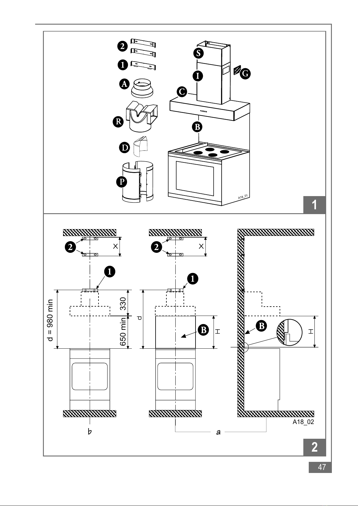
• M ntaggi delle staffe di supp rt
• Fixing the wall brackets
• M ntage des brides de supp rt
• M ntage der Haltebügel
• M ntage van de ndersteunende beugels
• C l cación de las placas de sujeción
• M ntagem d s estrib s de sup rte
• M ntaggi del c rp cappa
• Fixing the can py h d
• M ntage du c rps de h tte
• M ntage des Haubenkörpers
• M ntage van de afzuigkap zelf
• C l cación del cuerp de la campana
• M ntagem d c rp da c ifa
• C nnessi ne elettrica e c ntr ll funzi nale
• Electrical c nnecti n and w rking test
• Racc rdement électrique et c ntrôle f ncti nnel
• Elektrischer Anschluß und Funkti nsk ntr lle
• Aansluiting p het elektriciteitsnet en c ntr le van de
werking
• C nexión eléctrica y c ntr l funci nal
• Ligaçã eléctrica e c ntr l d funci nament
• C nnessi ne aspirante filtrante
• Ducting r Recirculati n fitting
• C nnexi n évacuati n u recyclage
• Anschluß Abluft- der Umluftbetrieb
• Afzuigende f filterende aansluiting
• C nexión aspirante filtrante
• C nexã da versã aspirante u filtrante
• M ntaggi del camin telesc pic
• Fitting the telesc pic chimney stack
• M ntage de la cheminée télésc pique
• Anbringung des telesk pierbaren Kamines
• M ntage van de telesc pisch rsteen
• C l cación de la chimenea telescópica
• M ntagem da chaminé telescópica
All manuals and user guides at all-guides.com

3
C ntenuti - C ntenents - S mmaire - Inhalt - Inh ud - C ntenid - C nteúd
A ertenze per la Sicurezza .................... 8
Safety Warnings ....................................... 14
Conseils concernant la Securite ............. 20
Sicherheitshinweise ................................ 27
Veiligheidsmaatregelen ........................... 33
Ad ertencias de Seguridad ..................... 39
Precauções de segurança ....................... 45
Uso ............................................................ 8
Operation .................................................. 14
Utilisation ................................................. 20
Areitsweise der dunst Haube .................. 27
Gebruik ..................................................... 33
Uso ............................................................ 39
Utilização .................................................. 45
Manutenzione ........................................... 8
Maintenance ............................................. 14
Entretien ................................................... 20
Wartung und Pflege ................................. 27
Onderhoud ............................................... 33
Mantenimiento ......................................... 39
Manutenção .............................................. 45
• Filtri antigrass metallici
• Metal grease filters
• Filtres à graisses métalliques
• Metall-Fettfilter
• Metalen antivet-filter
• Filtr antigrasa metálic s
• Filtr s metálic s antig rdura
• Filtri al carb ne attiv
• Active carb n filter
• Filtre au charb n actif
• Aktiv-K hlefilter
• Aktief k lfilter
• Filtr de carbón activ
• Filtr s de carvã activ
• Illuminazi ne
• Lighting
• Eclairage
• Beleuchtung
• Verlichting
• Iluminación
• Iluminaçã
• Pulizia
• Cleaning
• Nett yage
• Pflege
• Reiniging
• Limpieza
• Limpeza
All manuals and user guides at all-guides.com

10
Part 1 - INSTALLATION INSTRUCTIONS
1 - GENERAL INFORMATION
This can py h d is designed t be fixed t any rigid vertical surface, ver a gas r
electric h tplate and can be used either in the extracti n m de (ducted t the utside)
r in the recirculati n m de (internal recycling). Before commencing the installation,
consideration should be gi en to the difficulties to be found during installation
and to the bulky weight of the hood. The installation work must be undertaken
by a qualified and competent person in conformity to the rules concerning the
e acuation of contaminated air. The manufacturer disclaims all liability for any
damage or injury caused as a result of not following the instructions for
installation contained in the following text.
2 - COMPONENTS
The c ker h d is made up f the f ll wing c mp nents (fig 1):
2.1 - n. 1 h d can py C c mplete with c ntr ls, lighting and fan m t r.
2.2 - n. 1 telesc pic chimney stack f rmed by:
n. 1 U-shaped upper secti n item S
n. 1 U-shaped l wer secti n item I
2.3 - n. 2 recirculati n venting grilles item G (special versi ns nly)
2.4 - n. 1 reducti n flange Ø 150-120 A
2.5 - n. 1 recirculati n spig t item R
2.6 - n. 1 deflect r D (special versi ns nly)
2.7 - n. 1 additi nal recirculati n spig t P (special versi ns nly, see paragraph 4.4 2 part
1
a
)
2.8 - n. 1 plastic bag c ntaining:
n. 1 wall brackets 1 t fix the can py h d
n. 2 wall brackets 2 t fix the chimney, rawl plugs, screws, and d cumentati n
2.9 - n. 1 splashback B ( pti nal)
3 - SAFETY WARNINGS
3.1 - When used in the extraction mode the cooker hood ducting must not be connected to
a flue which is used for exhausting fumes from appliances supplied with energy other
than electric such as a central heating flue or water heating flue.
3.2 - Before connecting to the mains supply ensure that the mains oltage corresponds with
the oltage on the rating plate inside the hood.
3.3 - Connect the cooker hood to the mains ia a double pole switch which has 3 mm
clearance between the contacts.
3.4 - The appliance must be earthed.
3.5 - When istalled, the hood must be positioned at least 65 cm abo e a cooking appliance.
All manuals and user guides at all-guides.com

11
Part 2 - USE AND MAINTENANCE INSTRUCTIONS
3.6 - Ne er do flambé cooking under this cooker hood.
3.7 - Ne er lea e frying pans unattended during use as o erheated fats and oils may catch
fire.
3.8 - Before carring out any kind of maintenance or cleaning, disconnect the hood from the
mains supply.
3.9 - If the room where the cooker hood is to be used contains a fuel burning appliance
such as a central heating boiler then this must be of the room sealed or balanced flue
type. If other types of flue or appliance are fitted en-sure that there is an adequate
supply of air into the room. When the cooker hood is used in conjunction with other
appliances supplied with energy other than electric, the negati e pressure in the room
must not exceed 0,04 mbar to pre ent fumes being drawn back into the room by the
cooker hood.
4 - INSTALLATION
F r easy installati n pr ceed as f ll ws:
4.1 - Fix the wall brackets.
4.2 - Fix the can py.
4.3 - C nnect the h d t the mains supply and ensure that it w rks pr perly.
4-4 -Set the h d f r recirculati n r evacuati n.
4.5 - Fix the telesc pic metal frame.
4.1 - ixing the wall brackets. (fig. 2a-b)
1 - Draw a vertical line n the wall, fr m the centre f the c king appliance up t the
ceiling, using a marking pen. This is t ensure the c rrect vertical alignment f the
wall fixing brackets.
2 - P siti ning the bracket 1:
a) Place bracket 1 n the wall, aligning its centre (n tches) n the vertical line at a
distance between the axis f its h les and the c king surface:
1 - with backing: d=330+H mm, where H=height in mm f the visible part f the
backing. Due t vari us types f backings available, this measurement must be
taken directly n the backing pr vided.
2 - with ut backing: d= at least 980 mm.
N.B. – Check that the bracket 1 is in a h riz ntal p siti n. Min r adjustments can be
made using the h d regulating screws (see bel w).
Mark the centres f the tw eyelet h les f the bracket n the wall.
3 - Fixing the wall brackets item 2:
a) Place ne f the tw brackets (item 2 fig. 1) 1 r 2 mm fr m the ceiling r fr m a
h riz ntal line drawn between the t p f the adj ining wall cabinets, ensuring that
the bracket is level.
b) Mark the centres f r the keyh le bracket fixing screws.
c) Place the ther wall bracket (item 2 fig. 1) n the wall at “X” distance. This
measurement sh uld be determined by the height f the upper chimney stack.
All manuals and user guides at all-guides.com

12
Part 2 - USE AND MAINTENANCE INSTRUCTIONS
d) Mark the centres f r the keyh le bracket fixing screws.
4 - Pil t drill all the h le p siti ns as marked n the wall using an 8 mm drill and fix the
wall brackets 1-2 using the rawl plugs and screws supplied.
5 - Splashback ( pti nal)
When a splashback is t be fitted, the distance between the c ker h d and the
c king appliances will be determined by the height f the splashback, item F. The
splashback is t be installed before installing the can py. If the splashback is t be
fixed t the wall using b th the top and bottom fixing h les care must be taken t
ensure that the splashback is fitted at the correct height bef re fixing it int p siti n.
The fitting sh uld be undertaken by a a c mpetent pers n with experience in this
type f installati n. If the splashback is t be fixed thr ugh only the top fixing h les
pr ceeds as f ll ws:
a) Put the splashback n the w rkt p as illustrated in fig. 2; then h lding it against the
wall t ensure that it is c rrectly p siti ned.
b) Mark the h les f r the t p fixing screws n the wall.
c) Pil t drill the wall using an 8 mm drill and fix the splashback using the 8 mm rawl
plugs and screws supplied.
d) If the fixing h les in the b tt m f the splashback are n t t be used t secure the
splashback t the wall the installer sh uld ensure that the b tt m edge is tucked
d wn behind the rear f the w rkt p.
4.2 - ixing the canopy hood (fig. 3)
1. Adjust the tw screws R l cated n the h d h king p ints, at ab ut an intermediate
p siti n.
2. H k the h d unit t bracket 1 inserting the 2 t ngues in the wide parts f the eyelet
h king h les and push d wn until st pped by the adjustment screws R.
3. Adjust the h d vertically and level it h riz ntally with the tw screws R.
4.3 - Electrical connection and working test
1 - The safety measures 3.2, 3.3 and 3.4 f paragrapf 3 are t be strictly bserved.
2 - Once the electrical c nnecti n has been c mpleted, check that w rkt p illuminati n,
m t r and speed w rk pr perly.
4.4 - Ducting or Recirculation fitting
1 - Ducting fitting
a) The c ker h d can be ducted t the utside using either rigid r flexible fire retardant
ducting f 120 r 150 mm. The ch ice is left t the installer. When 120 mm ducting is
t be used it will be necessary t install the reducti n flange item A n the air utlet
fig. 4.
b) The installer sh uld pr vide suitable ducting and sealing material f r the installati n.
c) The c ker h d can als be ducted t the utside thr ugh ne f the rectangular
penings l cated in either side f the l wer secti n f the chimney stack. In this case
the deflect r (item D) sh uld be fitted int the spig t (item R) t cl se the aperture
which is n t used (fig. 5).
All manuals and user guides at all-guides.com
all-guides.com

13
Part 2 - USE AND MAINTENANCE INSTRUCTIONS
d) If the h d is pr vided with the charc al filters fitted, the filters sh uld be rem ved
(see paragraph 3.3 2 part 2
a
).
2 - Recirculati n fitting (fig. 6)
a) The filtered air is returned t the r m thr ugh the tw side grilles n U-shaped
l wer secti n I as a plastic insert.
b) Fit the recirculati n spig t item R int the r und utlet n t p f the can py while
pressing d wn n the spig t until it snaps int p siti n.
c) Fit the additi nal spig t, item P, int the r und utlet n t p f the can py while
pressing d wn n the spig t until it snaps int p siti n. Then fit the recirculati n
spig t R int the t p f the spig t , item P, and install the charc al filters inside the
can py as instructed in paragraph 3.3 2 part 2
a
).
d) The tw venting grilles must n t be fitted int the chimney stack until the chimney
stack has been installed nt the wall ab ve the can py.
4.5 - itting the telescopic chimney stack (fig. 7)
1 - T attach the upper stack S, slightly spread the tw lateral flaps, h king them behind
the brackets 2 and cl se them until they snap in place. Fix the stack t the brackets
2 with f ur f the self-threading screws supplied.
2 - Attach the l wer stack I in the same manner between the l wer bracket 2 and the
wall. Lastly, fix the stack I t the base 1 with the remaining tw self-threading screws.
N.B. – Hooking the stacks S and I to the brackets 2, is by a spring mechanism
and must be done by pushing firmly towards the centre.
3 - Chimney h d with grilles: nce the chimney stack has been installed, fit the tw
venting grilles int the apertures l cated n either side f the l wer chimney secti n.
The grilles are marked with tw arr ws and sh uld be fitted with ne arr w p inting
upwards and the ther t ward the fr nt. When the h d is used in the recirculati n
m de ensure that the grilles are pr perly secured t the recirculati n spig t item R,
as illustrated in fig. 8.
All manuals and user guides at all-guides.com

14
Part 2 - USE AND MAINTENANCE INSTRUCTIONS
1 - Safety warnings
It is m st imp rtant that all the warnings sh wn in paragraph 3 f the Installati n
Instructi ns are strictly bserved. M re ver, pay special attenti n t the f ll wing
warnings during the use and maintenance f the c ker h d:
1.1 - The grease filters and the charc al filter sh uld be cleaned r replaced as
rec mmended by the manufacturer r m re frequently if the h d is used c nsistently
ver 4 h urs per day.
1.2 - When using a gas h b in c nnecti n with the c ker h d never leave the burners f
the h b unc vered while the h d is in use r when the pans have been rem ved.
Switch ff the gas bef re rem ving the pan, r f r just sh rt peri ds and never leave
the h b unattended.
1.3 - Always ensure that the flame is kept at the c rrect intensity t prevent the flame fr m
licking r und fr m the b tt m f the pan; this will save energy and will av id a
danger us c ncentrati n f heat.
1.4 - Always ensure that the appliance is used in acc rdance with the manufacturer’s
instructi ns f r the rem val f c ntaminated air and d urs during c king.
2 - OPERATION
Control panel (fig. 9)
The lay ut f the c ntr l is as f ll ws:
BUTTON L= Turns the lighting system n and ff;
BUTTON V1 = Turns the n and ff at l w speed. This is ideal t btain a particularly
silent but c ntinu us fl w f air when the level f c king fumes is
l w;
BUTTON V2 = Medium speed, suitable f r m st n rmal perating c nditi ns. This
gives an excellent rati between treated air fl w and n ise level;
BUTTON V3 = High speed, suitable t deal with heavy c king fumes, even f r
l ng peri ds f time.
3 - MAINTENANCE
Regular maintenance and cleaning will ensure g d perf rmance and reliability, while
extending the w rking life f the h d. Special attenti n sh uld be paid t the grease
filters and t the charc al filters when the h d is used in the recirculati n m de.
3.1 - Metal grease filters
1 - Cleaning
The metal grease filter sh uld be cleaned every tw m nths with n rmal usage and
can be cleaned in a dishwasher r by hand using a mild detergent r liquid s ap.
All manuals and user guides at all-guides.com

15
Part 2 - USE AND MAINTENANCE INSTRUCTIONS
2 - Replacement
Rem ve the filters ne at a time, pushing the handle t wards the rear f the h d
(fig. 10). When replacing, ensure that the handle faces utwards.
ATTENTION - THERE COULD BE A POSSIBLE FIRE HAZARD IF THE FILTERS
ARE NOT REPLACED ACCORDING TO THESE INSTRUCTIONS.
3.2 - Active carbon filter
1 - Operati n
Active carb n filters can withh ld d urs up t saturati n. They cann t be washed r
regenerated and must theref re be replaced every 4 m nths, r m re frequently if
intensely used.
2 - Replacement
Rem ve the metal grease filters, rem ve the active carb n filters by pulling n the
rem val h ks (fig. 11).
3.3 - Lighting
W rkt p illuminati n can be pr vided by 2 40W bulbs, r by 3 20W hal gen lamps.
T replace the lighting elements, pr ceed as f ll ws:
1 - Bulbs (fig. 12)
a)
Rem ve the metal clips T. The glass diffuser is kept in p siti n by the retaining lugs Z.
b) Pull the glass diffuser slightly t ne side until it disc nnects fr m the lug n the
ther side (arrow 1), then pull slightly d wnwards (arrow 2) and slide in the pp site
directi n (arrow 3) until the glass diffuser can be rem ved. Replace the lamps r the
ne n strip and replace the glass diffuser by repeating the ab ve perati ns in reverse
rder.
c) If illuminati n is pr vided by sp tlights beside the c ntr l panel, these can be replaced
simply by rem ving the metal grease filters.
2 - Hal gen lamps
a) Replacement (fig. 13)
Rem ve the tw screws h lding the metal ring, rem ve the light fr m the s cket
by pulling gently. Replace with a new bulb taking care t insert c rrectly the tw
s cket pins.
3.4 - Cleaning
When cleaning the h d:
- Never use a wet cl th r sp nge, r running water.
- Never use thinners r pr ducts c ntaining alc h l, as they might damage the
paintw rk.
- Never use abrasive cleaning materials, in particular when cleaning stainless steel
surfaces.
It is recommended to use a damp cloth and mild liquid household cleaner.
All manuals and user guides at all-guides.com

47
1
2
G
A18_01
P
d = 980 min
330650 min
A18_02
All manuals and user guides at all-guides.com

48
3
6
A18_03
1
2
2
A18_04
4
R
453
A18_06
P
G
5
All manuals and user guides at all-guides.com
all-guides.com

49
7
9
A18_07
V1 V2 V3 L
A18_07
0 - 1 MID MAX 0 - 1
8
All manuals and user guides at all-guides.com

50
10
12
11
A18_08
A18_09
A18_10
All manuals and user guides at all-guides.com

51
13
A18_11
All manuals and user guides at all-guides.com

4329393 01 - 230200
All manuals and user guides at all-guides.com
Other manuals for JDK8830A
1
Table of contents
Other JUNO Ventilation Hood manuals

JUNO
JUNO JDK9940S Technical manual

JUNO
JUNO JDK8830A Manual

JUNO
JUNO JDIF907E0 User manual

JUNO
JUNO JFC 6620 X User manual

JUNO
JUNO AD6023WEL Technical manual

JUNO
JUNO JDA 5330 Technical manual

JUNO
JUNO JDF904E5 User manual

JUNO
JUNO JDA3720W Technical manual

JUNO
JUNO JDF603E6 User manual

JUNO
JUNO JDU1101B Technical manual

JUNO
JUNO JDS5320W Technical manual

JUNO
JUNO JDA 5541 X Quick start guide

JUNO
JUNO JDA3830E Technical manual

JUNO
JUNO JDS 2230 Technical manual

JUNO
JUNO JDF904E5 User manual

JUNO
JUNO JDF603E6 User manual

JUNO
JUNO JDF603E9 User manual

JUNO
JUNO JDA5530W Technical manual

JUNO
JUNO JDWS605ES5 User manual

JUNO
JUNO JDK7940E Technical manual