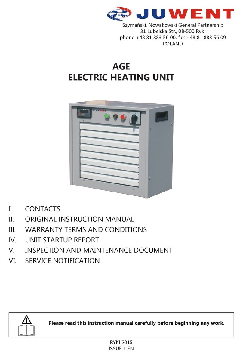
Juwent UVERS W User manual

UVERS
UNIT HEATERS
Szymański, Nowakowski Sp. j.
31 Lubelska Str., 08-500 Ryki
phone +48 81 883 56 00
POLAND
I. CONTACTS
II. ORIGINAL OPERATING INSTRUCTIONS
III. WARRANTY CONDITIONS
IV. STARTUP REPORT
V. INSPECTION AND MAINTENANCE CHART
VI. SERVICE REQUEST FORM
VII. LIST OF COMPONENTS INSTALLED IN THE PRODUCT
Read the instruction manual carefully before starting work.
EDITION EN 250523

2www.juwent.com.pl
I. CONTACTS
Szymański, Nowakowski General Partnership
31 Lubelska Str., 08-500 Ryki
phone +48 81 883 56 00,
POLAND
Export department
mob.+48 502 087 841
mob.+48 664 465 243

3www.juwent.com.pl
II. ORIGINAL OPERATING INSTRUCTIONS
UVERS
UNIT HEATERS

4www.juwent.com.pl
TABLE OF CONTENTS
1. INTENDED USE 5
2. DESIGNATIONS 5
3. DESCRIPTION 6
4. TECHNICAL DATA 6
5. TRANSPORTATION 7
6. SAFETY RECOMMENDATIONS 8
7. INSTALLATION 9
8. WATER SYSTEM - UVERS W 10
9. REFRIGERATION SYSTEM - UVERS DX 11
10. ELECTRICAL WIRING 11
11. CONTROLS 13
13. START-UP 18
12. REPAIR, MAINTENANCE AND DECOMMISSIONING 19
14. TROUBLESHOOTING 20
15. INFORMATIONS 20

5www.juwent.com.pl
1. INTENDED USE
UVERS W unit heaters are designed to be fed with hot water from low temperature heat sources
such as heat pumps or gas-red boilers. They can also be fed with chilled water to provide cooling.
UVERS DX unit heaters are suitable for use alongside air-to-air heat pumps. Thanks to the reversible
system, they can also provide a cooling function.
The unit heaters are designed for heating and cooling areas such as:
» factory oors,
» workshops,
» warehouses,
» sports and entertainment halls.
Unit heaters cannot be used in areas with relative humidity above 95% and air dust
concentration above 3mg/m3.
UVERS W units can be fed with water at a maximum temperature of up to 150°C and an
operating pressure of up to 1.5MPa.
Unit heaters are suitable for vertical operation with a maximum inclination from the
vertical plane of 25°.
UVERS DX units can be fed by R410A refrigerant;
working pressure up to 3.5MPa.
When the unit heater is operating in cooling mode, condensation may be entrained by
the air stream. Follow the instructions in this manual.
2. DESIGNATIONS
Unit heater UVERS W -1 -III -EC
Size 1; 2
Number of coil rows II; III
Fan type AC; EC
Unit heater UVERS DX -1 -III -EC
Size 1; 2
Number of coil rows III
Fan type AC; EC

6www.juwent.com.pl
3. DESCRIPTION
The unit heater consists of:
»axial fan with AC or EC single phase motor;
»coil made of copper tubes with an external diameter of 12 mm and aluminium ns with n
spacing s=2.4 mm.
UVERS W is available with two types of coils: 2 or 3 row coils adapted to work with low
temperature heat sources and 3 row coils suitable for cooling function as they can be fed with chilled
water. UVERS DX is only available with a 3-row coil suitable to work with heat pumps using R410A
refrigerant in a two-pipe reversible system.
»casing with single-row outlet grille which helps to increase the air throw.
Accessories:
» specially designed wall mounting bracket that allows the position of the unit heater to be
adjusted at an angle of ± 45° in the horizontal plane and at an angle of 25° plane;
» drip tray for collecting the condensate generated during the cooling process.
4. TECHNICAL DATA
Unit heater size UVERS W-1 UVERS W-2
A (mm) 556 677
B (mm) 527 686
h (mm) 460 620
Number of coil rows II III II III
d1l d23/4’’ l 3/4’’ 3/4’’ l 3/4’’ 3/4’’ l 3/4’’ 1’’ l 1’’
Volume (dm3)1.5 2.0 2.4 3.2
AC L (mm) 445 461
weight (kg) 26 28 41 47
EC L (mm) 350 423
weight (kg) 24 26 46 52

7www.juwent.com.pl
Unit heater size UVERS DX-1 UVERS DX-2
A (mm) 556 677
B (mm) 527 686
h (mm) 460 620
Number of coil rows III III
d1l d212 l 22 12 l 28
Volume (dm3)2.0 3.2
AC L (mm) 445 461
weight (kg) 29 49
EC L (mm) 350 423
weight (kg) 27 54
AC fans parameters
Supply voltage (V) 230 230
Motor power (W) 140 250
Current (A) 0.65 1.2
Speed (rpm) 1400 1350
IP 54 54
Operating temperature 60°C 60°C
EC fans parameters
Supply voltage (V) 230 230
Motor power (W) 140 332
Current (A) 1.45 2.16
Speed (rpm) 1160 1300
IP 54 54
Operating temperature 40°C 70°C
Noise level
UVERS DX-1-AC UVERS DX-1-EC UVERS DX-2-AC UVERS DX-2-EC
Noise level (dB(A)) 53 56 62 64
Noise level — sound pressure level taking into account the sound absorption in the room A=100m2 and directivity factor Q=2 at a
distance of 5 m.
5. TRANSPORTATION
The unit heaters are supplied complete, in cardboard packaging to protect them from dirt and
atmospheric inuences.
The instruction manual is delivered with the unit heater.
The controls are supplied separately on request.
The unit heaters should be shipped in no more than two layers with padding to prevent
mechanical damage.

8www.juwent.com.pl
6. SAFETY RECOMMENDATIONS
The unit heaters should only be used in accordance with the instruction manual.
The start-up, installation, connection, inspection and repair of the unit should be carried
out by an authorized contractor, the electrical work should be carried out by a person
with the required certicates authorized to carry out electrical work.
All maintenance and repair work must be carried out when the power is off.
In the event of a malfunction, immediately disconnect the motor from the power supply
and shut off the heating medium supply to the coil.
The unit heater may only be operated with correctly functioning electrical safety devices.
It must be permanently connected to an electrical system equipped with a protective
(grounding) terminal, a residual current device and a service switch.
Use only original spare parts.
It is forbidden to operate the unit heater with the fan without a protective grille.
Caution!
Failure to install or operate the unit heater in accordance with the operating instructions may
result in damage to the unit heater and void the warranty.
Due to its design, the unit heater does not emit any hazardous radiation.
Despite the fact that the product has been designed and manufactured in accordance with the
standards in force at the time of manufacture, there is an unavoidable risk of injury or damage to
health when using the product. This probability is related to the frequency of use, cleaning and
repair of the unit heater, the presence of persons in the danger zone and failure to comply with
the safety rules set out in the instructions. The severity of physical injury and deterioration in health
depends on many conditions which can only be partially anticipated by taking them into account
in the design of the equipment and by providing descriptions and warnings in the instructions for
use. Therefore, there is a residual risk if the recommendations and instructions are not followed by
the operator.

9www.juwent.com.pl
7. INSTALLATION
The walls, ceilings or structural parts of the building to which the brackets or other suspensions
of the unit heaters are attached should be of adequate strength. This should be agreed with the
building designer.
The supporting structures for the unit heater can be freely designed according to the
strength requirements.
If it is necessary to mount the unit on a partition wall, e.g. made of sheet metal,
reinforcement should be used to prevent vibrations of the partition wall caused by the
operation of the unit heater and an increase in the noise level in the room.
The minimum distance from the wall or ceiling required to ensure free passage of the air
to the fan is 30 cm for the UVERS-1 units and 40 cm for the UVERS-2 units measured
from the rear face of the unit casing.
Mounting brackets
» The units can be mounted on the wall using the mounting bracket that is available as an
accessory for the UVERS units.
» It allows the unit heater to be rotated ± 45° in the horizontal plane and tilted 25° in the vertical
plane.
» The bracket should be fastened to the unit heater with M8 x 60 bolts using spacer sleeves.
90°
25°
D
UVERS Unit
Heater
KM-UVERS
TC-UVERS
Ǿ 11
E
Spacer sleeve
Wall bracket D
(mm)
E
(mm)
Bracket weight
(kg)
Condensate drip
tray
Weight of dip
tray
(kg)
KM-UVERS-1 682 645 3.1 TC-UVERS-1 2.0
KM-UVERS-2 782 804 3.6 TC-UVERS-2 2.5
» For units with a cooling function, use a drip tray and position the blades of the outlet grille
at a 45° angle to prevent condensation from being carried away.
» The unit heaters with drip tray must be operated perpendicular to the wall to allow
condensation to drain (do not tilt the unit heater!).
» The condensate drip tray has a drain connection ⵁ 11mm.
» The condensate can be discharged directly to the sewer or via a condensate pump.
» The drip tray should be installed under the unit heater and fastened to the mounting bracket
with an M8 x 60 bolt.

10 www.juwent.com.pl
8. WATER SYSTEM - UVERS W
UVERS units with water coils can be fed with water at a maximum temperature 150°C
and working pressure up to 1.5MPa.
It is recommended:
» to connect the bottom connection of the coil to the supply pipe of the heating system and the
return pipe to the top connection;
» to use shut-off valves on the supply and return pipes to allow the unit heater to be removed
without draining the heating system.
The solenoid valves should be installed in the supply line upstream of the coil.
Unit heater coils should be vented and drained centrally in the network using air vents and drain
valves.
Centralised drainage of the water coil is not possible for ceiling-mounted unit heaters.
Inaccurate venting of the coil may be the reason why the unit heater does not achieve
the desired parameters.
The coil connections are not intended to bear the weight of the pipework.
When connecting the pipes to the coil, the connections must be secured against over-tightening
and consequent damage to the thread, as shown in the gure below.
Damage to the coil caused by the above is not covered by the warranty.

11www.juwent.com.pl
9. REFRIGERATION SYSTEM - UVERS DX
UVERS DX units can be fed by R410A refrigerant; working pressure up to 3.5MPa. Use of
the DX coil with other operating parameters requires consultation with the manufacturer.
The DX coil is designed to be connected to the refrigeration system by brazing.
After leak and pressure testing, the coil is lled with nitrogen and its connections are
blanked off to prevent impurities from entering the coil.
Installation of the DX coils should only be carried out by qualied personnel.
The DX coils are designed for use in reversible system.
During installation, ensure that:
» the coil is correctly connected taking into account its connection side,
» the coil is connected to the system in such a way as to avoid bending and torsion of its
headers.
The pipework should be designed and installed on supports to minimise transmitted vibration and
to avoid stress on the coil connections.
When connecting the pipes, pay attention to the diameter of the coil connection. The suction
line should allow the oil to return from the evaporator to the compressor by continuous gravity
(minimum slope 1cm/m). If it is not possible, it will be necessary to install a suction siphon at each
coil connection.
Soldering/brazing using a socket-type alloy tting is recommended to join two copper pipes, both
to ensure the strength of the joint and to reduce the risk of breakage due to vibration.
» Pipe sizes should be determined in accordance with good engineering design practice. Before
charging refrigerant, the system should be fully pressure tested, checked for leaks and dried to
remove moisture.
» The refrigeration system pressure test should be carried out when the system is complete (all
outer and inner units are connected). Use technical nitrogen at 4.2 MPa for the test. The test
pressure shall be held for at least 24 hours.
» Evacuate the refrigeration system in order to remove air and moisture from the inside. Connect
a vacuum pump to the system to perform evacuation. It is recommended that the vacuum pump
has a minimum ow rate of 4 l/s and a maximum vacuum of -756 mmHg. After switching off
the vacuum pump and closing the pressure gauge valves on the system, the vacuum should be
maintained continuously.
10. ELECTRICAL WIRING
The electrical wiring and the connection of power to the unit heater must be executed in accordance
with relevant requirements of standards and construction regulations.
Electrical connections of the unit heater can only be carried out by an authorized
electrician familiar with the instruction manual.
Before connecting, make sure that the mains voltage and frequency as well as protection values
are in accordance with the information given on rating plates of unit heaters. In the event of non-

12 www.juwent.com.pl
compliance, do not connect the unit. The unit heaters are equipped with single (1~230V/50Hz)
motors with internal thermal contacts Tk (routed to the terminal box or permanently connected to
the motor control circuit). When making the electrical connection of the fan, ensure that a service
switch (WS), overload and short-circuit protection are provided in the control box.
The warranty is void if the required protective devices are not provided and the thermal
contact Tk is not connected to the control circuit.
The fan power cable should be routed to the terminal box and fastened to the protection grille or
fan mounting brackets using cable ties. Connect the fan thermal contact to the fan power control
circuit.
The electrical connection of the motor must be made in accordance with the wiring diagrams in the
terminal box.
Example fan wiring diagrams for connecting and control are shown in Figure 1.
AC fan motor
EC fan motor
Fig. 1 Wiring diagrams for fans used in UVERS unit heaters
SAFETY SWITCH CABLE No 1
BLUE
BROWN
GREEN/YELLOW
External signal Maximum
speed
CABLE No 2
RED
BLUE
WHITE
YELLOW
CONTROL

13www.juwent.com.pl
11. CONTROLS
When the unit heater is operating in cooling mode, condensation may be entrained by the air
stream. In such a situation, the air ow should be reduced to the value indicated in the table (the
value marked with an asterisk) and the outlet grille blades should be set at an angle of 45°.
The following are the recommended maximum speed controller settings:
» for UVERS ...1-AC operation with reduced control voltage up to 180 VAC
» for UVERS ...1-EC operation at speed control signal ~ 8V DC
» for UVERS ...2-AC operation with reduced control voltage up to 155 VAC
» for UVERS ...2-EC operation at speed control signal ~ 6V DC
The controls for UVERS DX depend on the heat pumps used with the unit heaters.
The control options should be discussed with your heat pump supplier.
The UVERS W unit heaters can be supplied with:
- control box: wall-mounted in a closed enclosure (equipped with: main switch, overcurrent and
short-circuit protection devices, indicators), designed to ensure the operation of control system.
A single control box can control a number of unit heaters with one thermostat in AUTOMATIC /
MANUAL mode.
The control box (1~230V/50Hz) should be supplied from the main switchboard equipped with a
main switch and residual current device.
When controls are ordered with the unit heaters, wiring diagrams of the unit heaters and controls
are also provided.
Example control wiring diagrams for unit heaters with single-phase motors are shown in
Figures 2 through 6.
- Fan speed controller: ARW (1~230V/50Hz) ve-speed transformer enables air ow and heat
output control. Fan speeds are manually selected.
Speed controller
type ARW-1.2 ARW-3
PE-L1-N Input voltage (230V AC)
PE,U1,U2 Output voltage (control
voltage)
Supply voltage
(V) 230 230
IP 21 21
Height (mm) 123 173
Width (mm) 77 90
Depth (mm) 71 89
- Room thermostat: The TP on/off room thermostat allows the desired room temperature to be
set within a range of 8 to 30°C using a rotary knob, while the TPP on/off room thermostat with LCD
display allows the desired temperature to be set within a range of 8 to 30°C in day and night mode.
TP or TP/IP65 Thermostat
Supply voltage 24..250V AC 24..250V AC
L-Y1 Heating
L-Y2 Cooling
Measurement range 8...+30OC8...+35OC
Contacts load 6(2)A 10(1.5)A
Protection degree IP30 IP65

14 www.juwent.com.pl
TPU Thermostat
Supply voltage 24..250V AC
L-Y Heating
and Cooling
Measurement range 8...+30OC
Contacts load 6(2)A
Protection degree IP30
TPP Programmable Thermostat
Supply voltage 2 batteries 1,5V
Q11-Q14 Heating
Q11-Q12 Cooling
Measurement range 5...+35OC
Contacts load 5(2)A
Protection degree IP30
-V 3-way Valves : The diverting valves are widely used to control the ow of uid through the coils.
Three-way diverting valves with V20 internally threaded connection (on/off) are used. The valves
shall be installed on the supply pipe, the ow is allowed only in the direction pointed out by the
arrow on the valve body: AB->A or AB->B.
Symbol DN kVS, m3/h t (OC) PN Unit type
V20 20 3.5 1...110 16 -1
-2
FITTINGS:
Z: cut-off valve: manual
P: Circulating pump
MV: 3-way control valve controlled
by the actuator
MV
P
ZAB
Z
Z
Z
Z
A
B
Unit Heater
Return
Power Supply
- MV Valve Actuators: designed for direct mounting on valves, providing valve control via
modulating 0-10V DC (when used with RT Controller) or on/off control signal (when used with TP
or TPP Thermostat). The position of the valve stem (retracted or extended) is proportional to the
control signal from the controller or thermostat.

15www.juwent.com.pl
Actuator type on/off modulating
signal
Supply voltage 230V AC 24V AC
Close / open time 180 s 150 s
Protection degree IP40 IP43
MV+V20 on/off actuator
L-N Supply voltage 230V AC
MV modulating actuator
Y Input control signal 0…10V DV
G0 System neutral
G System potential, 24V AC
- WS Service Switch: intended for switching off the fan motor in order to carry out service work.
The use of the WS switch prevents unexpected starting of the motor, which could cause a hazard
during service work.
Service switch type WS-3
Poles 3-poles
Supply circuit switch 3-phase
Continuous rated current 25A
Protection degree IP 65
Examples of wiring diagrams for unit heaters with AC fans.
Fig. 2 Wiring diagram for unit heater without controls

16 www.juwent.com.pl
Fig. 3 Wiring diagram for unit heater with speed controller
2
QII
QII
Q14
Q12
LY
THERMOSTAT
TPU
HEATING AND
COOLING
THERMOSTAT
TPP
HEATING
COOLING
THERMOSTAT
TP
HEATING
COOLING
10V
GND E1
+
-OUT
POSITIONER
Fig. 4 Wiring diagram for unit heater with controls (thermostat controls speed controller, valve actuator and fan
operation)
ZS Control Panel
POWER SUPPLY
SPEED CONTROLLER ROOM THERMOSTAT VALVE ACTUATOR
FAN MOTOR
Fig. 5 Wiring diagram for controls without ARW speed controller

17www.juwent.com.pl
ZS Control Panel
POWER SUPPLY
SPEED CONTROLLER ROOM THERMOSTAT VALVE ACTUATOR
FAN MOTOR
Fig. 6 Wiring diagram for controls with ARW speed controller
Examples of wiring diagrams for unit heaters with EC fans
10V GND E1
+-OUT
POSITIONER
Fig. 7 Wiring diagram for unit heater without controls
2
QII
QII
Q14
Q12
LY
THERMOSTAT
TPU
HEATING AND
COOLING
THERMOSTAT
TPP
HEATING
COOLING
THERMOSTAT
TP
HEATING
COOLING
10V
GND E1
+
-OUT
POSITIONER
Fig. 8 Wiring diagram for unit heater with controls (thermostat controls valve actuator and fan operation)

18 www.juwent.com.pl
ZS Control Panel
POWER SUPPLY
SPEED CONTROLLER ROOM THERMOSTAT VALVE ACTUATOR
FAN MOTOR
Fig. 9 Wiring diagram for controls
13. START-UP
Before start-up:
» ensure that the unit heater is properly mounted,
» check that all the water connections are tight,
» check that the supply voltage corresponds to that indicated on the rating plate,
» check up the additional protection of the fan and unit casing,
» check that the electric motor is correctly connected,
» check the direction of rotation of the fan.
To turn on the unit heater it is necessary to:
» open the appropriate valves on the supply and return lines and connect the unit heater to the
power supply,
» adjust the direction and throw of the discharged air using the outlet grille blades. The start-
up must be carried out by qualied personnel.
To turn off the unit heater it is necessary to:
» reduce the water ow to the heating coil (or shut off the feed water supply)
» The heating system should be designed and the unit heater should be selected taking into
account the maximum operating pressure. If necessary, appropriate precautions should be
taken to ensure that the value of this pressure is not exceeded.
» switch off the power supply to the electric motor of the fan.
In case of long standstills of the unit or breaks of heating network operation the heating
coil should be drained and the cut-off valves should be closed, if need be.

19www.juwent.com.pl
12. REPAIR, MAINTENANCE AND DECOMMISSIONING
The rolling bearings used in the fan do not require periodic relubrication. However, it is advisable to
check the condition of the motor bearings regularly (the fan impeller should rotate freely without
excessive play or knocking).
If the operating noise level of the unit heater increases, check that the fan and the entire unit are
properly mounted.
The impeller blades should be cleaned with a damp cloth after removing the protective grille in
order to prevent it from becoming unduly dirty and therefore unbalanced.
Do not use pressure washers to clean the fan.
In the event of a malfunction or faulty operation of the unit heater, contact the contractor or our
service department.
All repair and maintenance work should be carried out with the power supply
disconnected. The units heaters should also be protected against being accidentally
switched on by others.
The coils should be checked regularly for dust accumulation. If excessive, blow out the coils using
compressed air.
Excessive dirt build-up on the coil reduces heat transfer efciency and airow.
When the equipment is decommissioned, it should be disposed of at special collection points for
recycling.

20 www.juwent.com.pl
14. TROUBLESHOOTING
Description of
the problem Possible cause Solution
leaking coil
mechanical damage to the coil (can easily occur if
carelessly connected to the heating/cooling system)
always use two wrenches when connecting the coil to the
heating/cooling system
exceeding of the permissible water parameters for
heating
the heating system should be tted with safety devices to
prevent the water pressure and temperature from being
exceeded
frozen coil
use an anti-freeze thermostat, non-freezing heating
uids, or drain the water out of the coil if it is not expected
to operate for a long period and there is a risk of freezing
the unit heater is used in an aggressive environment
too loud operation
of the unit
minimum distance from the wall or ceiling is not
maintained use distances recommended in the instruction manual
improper direction of rotation of the fan execute a proper electric connection
improper parameters of the mains use the unit only when the parameters of the mains and
the unit are compliant
air outlet is blocked by outlet grid louvres avoid a signicant closing of outlet grid louvres at high
speed ratios
fan vibrations, the blades rub against xed elements check up the correctness of the fan and fastening
reliability of other elements of the unit
not centric fastening of the fan in its bearing plate
fan does not work
incorrect or unreliable electric connections check up or correct:
1) compliance of electric connections according to the
diagrams specied in the instruction manual
2) reliability of terminal connections
3) parameters of the mains
improper parameters of the mains (lack of three
phases in three-phase motors)
fan motor is damaged
fan operation control elements are damaged
ARW speed con-
troller does not
work
electrical connections are incorrect (loose terminal
block connections) check up or correct:
1) compliance of electric connections according to the
diagrams specied in the instruction manual
2) reliability of terminal connections
3) parameters of the mains
one controller is connected to more than one unit
heater
Actuator does not
actuate the valve
into the open po-
sition
The thermostat is not working correctly (there is no
characteristic clicking sound when switching)
check up or correct:
1) compliance of electric connections according to the
diagrams specied in the instruction manual
2) reliability of terminal connections
3) parameters of the mains
4) that the actuator has responded to the electrical im-
pulse. If the actuator is found to be damaged, a claim
should be made for the defective component.
Room thermostat
sends no signal
more than one unit heater is connected directly to
the thermostat (a greater number may overload the
thermostat)
check up or correct:
1) compliance of electric connections according to the
diagrams specied in the instruction manual
2) reliability of terminal connections
3) parameters of the mains
4) if there is no characteristic clicking sound, the thermo-
stat has been mechanically damaged and a complaint
should be made
location of the thermostat in the room
15. INFORMATIONS
In the event of any queries or doubts regarding the unit heaters, please contact the JUWENT
company or one of our representatives.
This manual suits for next models
1
Table of contents
Other Juwent Heater manuals
Popular Heater manuals by other brands

Harvia
Harvia KV30 Instructions for installation and use

Argo
Argo HIFAN operating instructions

Tutco-Farnam
Tutco-Farnam Heat Torch 150 quick guide

HEATFun
HEATFun PRO LINE Installation and user instructions

Saunatec
Saunatec 1106-105 Installation and operating instructions

Feider Machines
Feider Machines FCD37KW-1 instruction manual