JVA Z25 User manual

JVA TECHNOLOGIES
www.jva-fence.com
Z25 User ManUal

Page 2 Page 3© JVA Technologies Pty. Ltd. www.jva-fence.com JVA Z25 Manual
Contents
Contents
CONTENTS
1 Quick Start Guide ................ 6
1.1 Changing the Programming Options . . . . . .6
1.1.1 Relay Functions. . . . . . . . . . . . . . . 10
1.2 Summary of Keypad Functions . . . . . . . . 13
1.3 Jumpers . . . . . . . . . . . . . . . . . . 16
1.4 Quick Test of Configured Unit . . . . . . . . 16
1.5 Connecting your Z25 to the fence . . . . . . 18
2 Introduction................... 20
3 Features And Benefits ...........22
3.1 More Features . . . . . . . . . . . . . . . 23
4 Description ....................24
4.1 JVA Z25 - Exterior . . . . . . . . . . . . . 24
4.2 Front Panel Status Lights. . . . . . . . . . 25
4.3 Front Panel LCD Display . . . . . . . . . . 25
4.4 Inputs and Outputs . . . . . . . . . . . . . 25
4.5 Keypad (Optional) . . . . . . . . . . . . . . 25
4.6 Z-Series Models. . . . . . . . . . . . . . . 26
4.7 Z-Series LCD Keypad (Optional) . . . . . . . 26
4.8 Internal Beeper/Keypad Beeper . . . . . . . 27
4.9 Programmable Options . . . . . . . . . . . 27
4.10 Arm input And Key Switch . . . . . . . . . . 27
4.11 Gate Input . . . . . . . . . . . . . . . . . 27
4.12 Low Power Mode . . . . . . . . . . . . . . 27
4.13 Agricultural mode . . . . . . . . . . . . . 28
4.14 Group Simultaneous Pulse Feature . . . . . 28
4.15 Remote Control Unit (Optional) . . . . . . . 28
4.16 Cabling . . . . . . . . . . . . . . . . . . 28
4.17 Lightning Protection . . . . . . . . . . . . 29
4.18 Earth Loop Monitoring . . . . . . . . . . . 29
4.19 Noise and Interference . . . . . . . . . . . 29
4.20 PC Control . . . . . . . . . . . . . . . . 29
5 Installation ................... 30
5.1 Installation Steps . . . . . . . . . . . . . 30
5.2 Interior Configuration . . . . . . . . . . . 31
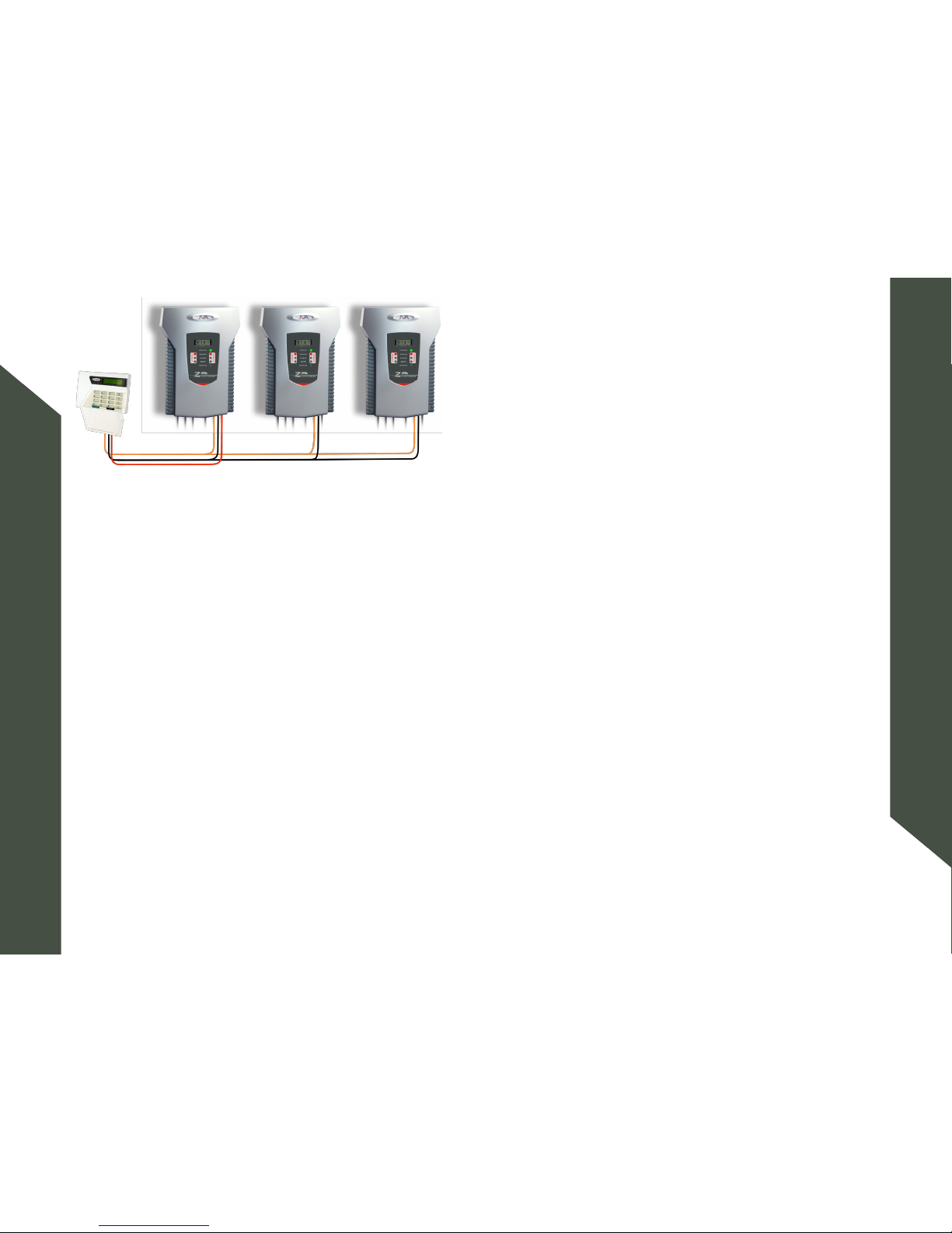
5.3 Example of Fence Wiring . . . . . . . . . . . 32
6 Control ......................33
6.1 Magnetic proximity switch . . . . . . . . . . 33
6.2 Arming the Fence Using the Keypad. . . . . . 33
6.3 ACTIVATING Low Power Mode . . . . . . . . 34
6.4 When an Alarm Occurs . . . . . . . . . . . 34
6.5 To Silence the Alarm . . . . . . . . . . . . 34
6.6 Changing the USER PIN . . . . . . . . . . . 35
6.7 Standby Battery . . . . . . . . . . . . . . 35
6.8 Status Light . . . . . . . . . . . . . . . . 35
7 Technical Information............36
7.1 Power Options . . . . . . . . . . . . . . . 37
7.2 Status Codes . . . . . . . . . . . . . . . . 38
7.3 Jumpers . . . . . . . . . . . . . . . . . . 38
8 Programming Options ............ 40
8.1 Programming Mode . . . . . . . . . . . . . 40
8.2 To Exit Programming Mode. . . . . . . . . . 40
8.3 Changing the Installer PIN . . . . . . . . . 40
8.4 Changing an Option . . . . . . . . . . . . . 40
8.5 Programming Options in Detail. . . . . . . . 41
8.5.1 Output Power Level (Option 1). . . . . . . . 41
8.5.2 Low Power Mode Output Voltage (Option 2) . 41
8.5.3 Fence Return 1 Alarm Voltage (Option 3) . . 42
8.5.4 Fence Return 2 Alarm Voltage (Option 4) . . 42
8.5.5 Fence Return Alarm Voltage for Low Power Mode
(Option 5) . . . . . . . . . . . . . . . . 42
8.5.6 Missed Pulse Count (Option 6) . . . . . . . 42
8.5.7 Siren On Time (Option 8) . . . . . . . . . . . 44
8.5.8 Siren Cycles (Option 10) . . . . . . . . . . 45
8.5.9 Gate Entry/Exit Delay (Option 13) . . . . . . 46
8.5.10 Chime Mode (Option 14) . . . . . . . . . . . 46
8.5.11 Combined Options (Option 16) . . . . . . . . 47

Page 4 Page 5© JVA Technologies Pty. Ltd. www.jva-fence.com JVA Z25 Manual
Contents
Contents
8.5.12 Anti-Bridging threshold (Option 17) . . . . . 48
8.5.13 Combined Options 2 (Option 18) . . . . . . . 48
8.5.14 Auto Re-arm Time (Option 20) . . . . . . . . 49
8.5.15 Relay Programming . . . . . . . . . . . . . 50
8.5.16 Group Mode (Option 26) . . . . . . . . . . . 52
8.5.17 Input Function and Trigger . . . . . . . . . 53
9 Specifications .................. 54
9.1 Z25 Specification . . . . . . . . . . . . . . 54
10 Z-Series Keypads ................56
10.1 PTE0210 LCD Keypad . . . . . . . . . . . . 56
10.2 PTE0230 Touch Keypad . . . . . . . . . . . 57
10.3 LCD Keypad Operation . . . . . . . . . . . . 58
10.3.1 Wiring up your Z-Series LCD Keypad . . . . . 58
10.3.2 Keypad status LEDs . . . . . . . . . . . . . 58
10.3.3 Arming/Disarming the Fence Using the Keypad 59
10.3.4 Menus . . . . . . . . . . . . . . . . . . . 59
10.3.5 Keypad Status Display. . . . . . . . . . . . 60
10.3.6 Changing the Keypad Messages and Address . 60
10.4 To Exit Keypad Programming . . . . . . . . . 62
10.5 Connecting Multiple Keypads to a system . . 62
10.6 Notes Regarding Keypad Configuration . . . 63
10.7 Calibrating the voltage display . . . . . . . 64
10.8 Using the PTE0230 Touch Keypad . . . . . . 66
10.8.1 Screens . . . . . . . . . . . . . . . . . . 66
10.8.2 Home Screen . . . . . . . . . . . . . . . . 66
10.8.3 Alarm Screen . . . . . . . . . . . . . . . . 68
10.8.4 Settings Screen . . . . . . . . . . . . . . 69
10.8.5 Events Screen . . . . . . . . . . . . . . . 72
10.8.6 Zones and Zone Details Screen . . . . . . . 73
10.8.7 Program Devices Screen. . . . . . . . . . . 74
11 Remote Control Unit ............ 76
11.1 Features . . . . . . . . . . . . . . . . . . 77
11.2 Installation. . . . . . . . . . . . . . . . . 77
11.3 Operation and configuration . . . . . . . . 78
12 Standard Requirements for Security
Electric Fences ................79
12.1 Definitions . . . . . . . . . . . . . . . . . 79
12.2 General requirements for electric fences . . 79
12.3 Particular requirements for electric animal
fences in Australia . . . . . . . . . . . . 81
12.4 Installation of electric security fences . . . 82
12.4.1 General . . . . . . . . . . . . . . . . . . 82
12.4.2 Location of electric security fence . . . . . 82
12.4.3 Prohibited zone for pulsed conductors . . . 83
12.4.4 Separation between electric fence and physical
barrier . . . . . . . . . . . . . . . . . . 85
12.4.5 Prohibited mounting . . . . . . . . . . . . . 86
12.4.6 Operation of electric security fence . . . . . 86
13 Appendix A: Group Simultaneous Pulse
Feature ....................... 88
13.1 Group Simultaneous Pulse Feature . . . . . 88
13.2 Group Mode Programming (Option 26) . . . . 88
13.3 Group linking via the Keypad “bus” . . . . . 89

Page 6 © JVA Technologies Pty. Ltd.
Quick Start Guide
Quick Start Guide
JVA Z25 Manual Page 7
Command Key1 Key2 Keys 3 and 4 Key5
Return 1 Fence
Alarm Voltage For
High Power Mode
0 3 Enter the value in Hundreds of Volts #
Example: to set 3.8kV, use 38 for keys 3 and 4. Default is 40 (4.0kV)
Return 2 Fence
Alarm Voltage For
High Power Mode
0 4 Enter the value in Hundreds of Volts #
Example: to set 3.8kV, use 38 for keys 3 and 4. Default is 40 (4.0kV)
Return Fence Alarm
Voltage For Low
Power Mode
0 5 Enter the value in Hundreds of Volts #
Example: to set 0.8kV, use 08 for keys 3 and 4. Default is 05 0.5kV)
Bad/Missed Pulse
Count Before Alarm
Triggers
0 6 Enter the number of Missed Pulses #
Example: to set 14 counts, use 14 for keys 3 and 4. Default is 03
-
age (Volts). Alarm
Value Shown, Re-
duced Power is 1V
less
0 7 00 01 02 03 04 05 06 07 08 09 #
9.0 9.5 10.0 10.5 11.0 11.5 12.0 12.5 13.0 13.5
Siren On Time
(S=Seconds,
M=Minutes)
0 8 00 01 02 03 04 05 06 07 08 09 #
10S 30S 1M 2M 3M 4M 5M 20M 45M 130M
1
QUICK START GUIDE
1.1
CHANGING THE PROGRAMMING OPTIONS
Default Installer PIN
012345
Default User PIN 1234
First you have to enter Programming mode.
Command Key1 Key2 Key3 Key4 Key5 Key6 Key7 Key8 Key9
Enter Programming Mode Installer Pin * 0 #
-
curity Energiser. Default Values are highlighted in grey.
Command Key1 Key2 Keys 3 and 4 Key5
Change the Installer
PIN 6 Digits
0 0 Enter the new 6 digit Installer PIN #
High Power Mode
Power Level
0 1 Enter the value in Hundreds of Volts #
Example: to set 8.2kV, use 82 for keys 3 and 4. Default is 85 (8.5kV)
Low Power Mode
Power Level
0 2 Enter the value in Hundreds of Volts #
Example: to set 1.3kV, use 13 for keys 3 and 4. Default is 11 (1.1kV)

Page 8 © JVA Technologies Pty. Ltd.
Quick Start Guide
Quick Start Guide
JVA Z25 Manual Page 9
Command Key1 Key2 Keys 3 and 4 Key5
(Like Combined
1 8 +1 +2 +4 +8 #
Siren
Chirp
on
Arm
Enable
Entry
Exit
Gate
4800
Baud
9600
Baud
Auto Re-arm Time
S=Seconds, M =
Min, D=Disabled
2 0 00 01 02 03 04 05 06 07 08 09 #
0S 30S 1M 2M 3M 4M 5M 6M 7M D
Relay 1 2 1 Explained under Default is 09 (Strobe 1) #
Relay 2 2 2 Explained under Default is 13 (Strobe 2) #
Relay 3 2 3 Explained under Default is 08 (Siren) #
Group Mode 2 6 00 01 02 Etc 15 #
No Group Master Slave 1 Slave 14
Input 1 2 7 #
Input 2 2 8 #
Input 3 2 9 #
Exit Programming
Mode
* #
Command Key1 Key2 Keys 3 and 4 Key5
(S=Seconds,
M=Minutes)
0 9 00 01 02 03 04 05 06 07 08 09 #
10S 1M 2M 5M 10M 20M 30M 40M 50M 60M
Siren Cycles 1 0 00 01 02 03 04 05 06 07 08 09 #
012345678 9
Gate Entry/Exit
Delay (S=Seconds,
M=Minutes)
1 3 00 01 02 03 04 05 06 07 08 09 #
0S 30S 1M 2M 3M 4M 5M 6M 7M 8M
Chime Mode 1 4 01 02 03 04 05 #
None Door Chime Siren Fence
Alarm
Gate Beeps
Plus Siren
you want. E.g. for
Max Power and Lim-
it output:
2 + 4 = 6 Therefore
enter 06 for keys 3
and 4
1 6 +2 +4 +8 +16 +32 #
Maximum
Power at all
Limits out-
put to 2.5J
Enables IR
Tamper.
Stop slaves
on comms
fail
Stop Ener-
giser send-
ing alarm
memory
Threshold
1 7 -
ing alarm. Default is 00 (Disabled)
#

Page 10 © JVA Technologies Pty. Ltd.
Quick Start Guide
Quick Start Guide
JVA Z25 Manual Page 11
Keys 3
and 4
15 Siren Caused by
Gate
Behaves like siren, only for Gate Alarms
16 Armed - Low
Power Mode
Triggers when Armed in Low Power mode
17 Group Armed
18 Group general
20 Host Control This Relay is completely controlled from a Host system such as Perimeter Patrol or a
Keypad. If the Host system is disconnected from the Energiser for more than 30 sec-
21 Host Control -
Not Fail Safe
This Relay is completely controlled from a Host system such as Perimeter Patrol or a
Keypad. If the Host system is disconnected then the Relay will maintain its current state
1.1.1
Keys 3
and 4
00 Fence 1
01
02 Armed 1
03 Fence 2
04
05 Armed 2
07 General
Latched (internal errors only)
08 Siren
Latched
09 Strobe
10 AC Fail Triggers on AC Fail
11 Low/Bad Bat-
tery
12 Tamper
14 Gate 1 or 2 Triggers on a Gate Alarm

Page 12 © JVA Technologies Pty. Ltd.
Quick Start Guide
Quick Start Guide
JVA Z25 Manual Page 13
1.2
SUMMARY OF KEYPAD FUNCTIONS
Command Key1 Key2 Key3 Key4 Key5 Key6 Key7 Key8 Key9 Key10
Arm/Disarm USER PIN #
Silence the Energiser Siren
1 4 7 0 #
Enter Programming Mode INSTALLER PIN * 0 #
Enter Keypad Programming Mode INSTALLER PIN * 0 1 #
Exit Programming (Any Mode) * #
Change a User PIN, 4 Digits USER PIN * 0 # [New
PIN]
#
USER PIN * 1 0 #
USER PIN * 1 #
USER PIN * 2 0 #
USER PIN * 2 #
USER PIN * 4 1 #
USER PIN * 4 1 #
USER PIN * 4 2 #
USER PIN * 4 2 #
USER PIN * 4 #
USER PIN * 5 2 #
USER PIN * 5 2 #
Key3 Input Trigger Key4
0 0
1 1
2 Momentary Toggle (Toggle between states) 2
3NO Pulse Extend (Extend a short Close signal by 3
seconds)
3
4NC Pulse Extend (Extend a short Open signal by 3
seconds)
4
5
6
7
8
9 Pass Through input signal to other device

Page 14 © JVA Technologies Pty. Ltd.
Quick Start Guide
Quick Start Guide
JVA Z25 Manual Page 15
Key1 Key2 Key3 Key4
Clear Alarm Memory * 1 #
Display the Group ID of the Energiser * 2 6 #
Siren Test * 6 3 #
* 6 4 #
Display the Stored Joules (while Armed) * 6 7 #
Power Boost * 9 9 #
Panic
(Trigger the Siren and Disarm the Energiser)
Press the Panic Key for 3
Key1 Key2 Key3 Key4
Re-ana lyse the Energiser Group * 6 8 #
* 5 1 #
* 5 3 #
* 5 4 #
* 5 5 #
Change Backlight Mode * 8 #
Display Keypad Model * 9 #
Command Key1 Key2 Key3 Key4 Key5 Key6 Key7 Key8 Key9 Key10
Re-enable Siren USER PIN * 5 1 #
USER PIN * 5 1 #
USER PIN * 5 4 #
USER PIN * 5 4 #
USER PIN * 5 3 #
USER PIN * 5 3 #
Arm in Agricultural Mode (No Alarms) USER PIN * 9
Reset and Display Firmware Version USER PIN * 6 8 #
Reset and Return to Factory Defaults INSTALLER PIN * 6 8 #

Quick Start Guide
Page 16 Page 17
Quick Start Guide
© JVA Technologies Pty. Ltd. www.jva-fence.com JVA Z25 Manual
picture below.
the unit should go into alarm as the fence will appear to be cut. Check that
as shown in the above photographs. Following that each energiser should
“13 Appendix A: Group Simultaneous Pulse
together via the keypad bus and tested using group Arm and Disarm com-
mands, they should all pulse in unison when armed.
1.3 JUMPERS
jumpers and what each one does refer to .
JUMPER FUNCTION
J3 Inhibit AC fail error.
J4 Factory default jumper
on power up.
Jumpers are located in the middle of the board above the Keypad Connec-
tor
1.4 QUICK TEST OF CONFIGURED UNIT
fence. The reason for this is that you could get spurious results if you test

Quick Start Guide
Page 18 Page 19
Quick Start Guide
© JVA Technologies Pty. Ltd. www.jva-fence.com JVA Z25 Manual
-
correctly you can begin to wire them to the real fence.
1.5
This is covered under . In
page 30
wired up you can begin to protect your perimeter.

Introduction
Page 20 Page 21
Introduction
© JVA Technologies Pty. Ltd. www.jva-fence.com JVA Z25 Manual
2 INTRODUCTION
Thank you for purchasing a JVA security electric fence energiser. The grow-
-
eter security. The reason for this popularity is simple – monitored electric
to other technologies.
DEMARCATION The JVA electric fence around your property
shows you mean business.
DETERRENCE The safe, powerful JVA shock is a strong
deterrent to intruders.
DELAY The barrier will help delay an intruder, giving
DETECTION The JVA’s voltage monitor warns you of any
tampering with the fence.
DEPENDABLE 60 seconds a minute, 60 minutes an hour,
24 hours a day, 365 days a year, your
JVA electric security fence is monitored by
an alert, sober, electronic watchman.
safe, high-voltage pulse and sends it down the fence live wires. The JVA
-

Features and Benets
Page 22 Page 23
Features and Benets
© JVA Technologies Pty. Ltd. www.jva-fence.com JVA Z25 Manual
3 FEATURES AND BENEFITS
Feature
Australian designed and man-
ufactured
High reliability and great service
Wall-mountable, robust en-
closure with easily detachable
PCB chassis
In built LCD voltage display
and status lights
Internal 7aH 12V recharge-
-
curity electric fence in the event of a
mains power failure
Ease of control and display of fence volt-
ages
-
management systems
Low Power mode -
age for during the day
Switched +12V outputs for Si-
ren and Strobe
-
ing user to breach of security
Earth monitor input Ensures that all the wires on the fence
Enclosed fence terminals Tamper resistant and prevents acciden-
tal contact with high voltage
3.1 MORE FEATURES
•
• 2 joules peak output energy
• High and low Power mode
•
• Alarms on fence short or open circuit
•
•
• Internal beeper
•
•
• Adjustable fence voltage level
• Three 12V dc switch outputs (also referred to as relays)
•

Description
Page 24 Page 25
Description
© JVA Technologies Pty. Ltd. www.jva-fence.com JVA Z25 Manual
4.2 FRONT PANEL STATUS LIGHTS
Status Light
POWER On whenever the unit has power
ARMED
when in Low Power mode
FENCE Green when voltage on and OK, Red when there is
a fence alarm
GATE On when there is a gate alarm
STATUS/FAULT
indicates any faults on the energiser. See the table
4.3 FRONT PANEL LCD DISPLAY
-
checked easily.
4.4 INPUTS AND OUTPUTS
See .
4.5
“8 Programming Op-
4 DESCRIPTION
4.1

Description
Page 26 Page 27
Description
© JVA Technologies Pty. Ltd. www.jva-fence.com JVA Z25 Manual
4.6
an animal is caught in the fence, causing the short, it will be in
IR Tamper circuit.
4.7
-
er. Arming and disarming, responding to alarms or just checking the fence
voltage, the LCD keypad makes this easy through a simple menu system or
“8 Pro-
.
“10.3.3 Arm-
.
4.8 INTERNAL BEEPER/KEYPAD BEEPER
will sound when there is a fence alarm, a gate alarm, a door chime or a
-
4.9 PROGRAMMABLE OPTIONS
“8.5 Programming Op-
. Each parameter has a factory set default.
4.10 ARM INPUT AND KEY SWITCH
to the right-hand side of the case for this purpose.
An external switch device, for example a remote receiver or access control
keypad, can also be wired into the energiser to arm and disarm the unit.
4.11 GATE INPUT
-
“8.5.17 Input
.
4.12 LOW POWER MODE
fence live wires operate at a much lower voltage, typically 500V peak. See

Description
Page 28 Page 29
Description
© JVA Technologies Pty. Ltd. www.jva-fence.com JVA Z25 Manual
59 for details on using the keypad to set Low Power mode.
4.13 AGRICULTURAL MODE
way test the fence without triggering any of the alarms. This mode should
threshold, however it will not trigger the alarm.
4.14 GROUP SIMULTANEOUS PULSE FEATURE
-
-
units in a group have simultaneous high voltage output pulses and act as
page 88
4.15
-
arm the energiser via a compact key chain fob remote control. If using the
remote control the siren can be used to acknowledge arming with 1 beep
“8.5.10 Chime Mode
.
4.16 CABLING
High voltage cabling (fence feed and returns) should be run using suitably
-
able. High voltage cables must never be run within the same conduit as low
voltage cables. A minimum distance of 30mm should be kept between high
voltage and low voltages cables.
not enter the enclosure via the cable entry area a silicon sealant (neutral
cure) must be used to seal all the cable passages.
4.17 LIGHTNING PROTECTION
-
reduce repair costs. They are available from your local dealer.
4.18 EARTH LOOP MONITORING
.
4.19 NOISE AND INTERFERENCE
-
croprocessors. The most likely cause of such noise is the high voltage out-
-
4.20 PC CONTROL
serial data adaptor, such as the PAE223 or TCP/IP using a PAE212.

Installation
Page 30 Page 31
Installation
© JVA Technologies Pty. Ltd. www.jva-fence.com JVA Z25 Manual
Ensure that the user understands how to change the User PIN and is in
possession of this Installer/User Manual and the installer’s contact details.
* NOTE: Keep high voltage and low voltage cables at least 30mm apart. Do
not run high and low voltage cables in the same conduit.
5.2 INTERIOR CONFIGURATION
High Voltage Terminals Low Voltage Terminals
5 INSTALLATION
5.1 INSTALLATION STEPS
1.
2. Design and build the fence. (Beyond the scope of this manual.) Ask your
3.
not in direct sunlight.
4.
screws.
5. Mount the housing by using 4 screws through the rear of the box.
6. Replace the PCB chassis.
7.
the wall.
8. Wire the low voltage cables to the PCB terminals*.
9. Wire the high voltage cable to the PCB terminals*.
10. If earth monitoring is not going to be used on the fence, connect a
bridge wire from earth out to earth return.
11.
12.
13.
14. Do not connect a live or neutral to the earth terminal.
15. Replace the front cover.
16. Turn AC power on.
17.
status light should stop blinking.
18. Arm the unit.
19. Check to ensure that a short anywhere on the fence triggers the alarm.

Installation
Page 32 Page 33
Control
© JVA Technologies Pty. Ltd. www.jva-fence.com JVA Z25 Manual
5.3
6 CONTROL
may be armed and disarmed using any of the following:
• Key switch or remote switch connected to the control input (IN1)
• Remote control radio receiver connected to IN1
• JVA permanent magnet key fob
•
• JVA GSM module *not all versions
• Windows PC running JVA Perimeter Patrol
• Low level interface (wired to control inputs and relay outputs) from a
-
tem (PSIM)
6.1
front label. The energiser will beep and toggle from armed to disarmed or
2.
6.2 ARMING THE FENCE USING THE KEYPAD.
Enter your (Default User PIN is 1234).
Make sure the red ARM light comes on.
•
• The fence will power up and if all is well (no faults) the system will be
ready to deter and detect.
• If there is a fault on the fence and it cannot achieve full voltage, the
LCD screen will indicate that there is a fault.
• To disarm the system, enter your User PIN and press #.

Control
Page 34 Page 35
Control
© JVA Technologies Pty. Ltd. www.jva-fence.com JVA Z25 Manual
6.3 ACTIVATING LOW POWER MODE
To switch to Low Power mode, enter your . In Low Power
Enter your User PIN and press *42# to switch back to Full Power mode.
connected to a control input, if it has been programmed accordingly. See
See
6.4 WHEN AN ALARM OCCURS
If the system is armed and the fence is tampered with, the fence light
turn on. If the energiser is connected to an alarm system for monitoring,
an alarm signal will be sent to the alarm company monitoring the alarm
system.
An alarm will also sound if the gate input is opened and the entry/exit de-
6.5 TO SILENCE THE ALARM
Enter 1470on the Keypad.This will silence the Siren but not disarm the
be ready to sound again for the next Alarm.
6.6 CHANGING THE USER PIN
• Enter the current (default is 1234) and press . This enters
User Programming mode.
• Enter your new (must be 4 digits) and then .
• Press to exit User Programming mode.
• Make sure your new User PIN works by using it to arm the energiser.
6.7 STANDBY BATTERY
Should there be a loss of mains power, the power light on the keypad will
-
pulse.
6.8 STATUS LIGHT
.

Technical Information
Page 36 Page 37
Technical Information
© JVA Technologies Pty. Ltd. www.jva-fence.com JVA Z25 Manual
Label Type
Output
L2+
1 Pin with
common
Ground
Output
Siren+
1 Pin with
common
Ground
-
18Vac 3 Way
or wiring codes demand it. This should be con-
nected to the cabinet or mains earth NOT the
fence earth.
B a t t e r y
leads
7.1 POWER OPTIONS
not the 18Vac input.
A 24Vdc 1.5A supply can be used in place of the 18Vac supply. The correct
stored energy in a 24Vdc plug-pack, an AC fail may take up to 5 minutes to
be reported.
7 TECHNICAL INFORMATION
Label Type
KEYPAD 3 Way Supplies power and data line for an external key-
pad. The +12 source on these terminals is pro-
INPUT 1 1 Pin with
common
Ground
Energiser control input 1 (dry contact momen-
tary) internally wired in parallel with the key
switch. Can be used for a remote switch or a ra-
dio receiver. The receiver may be powered from
the keypad +12V terminal.
INPUT 2 1 Pin with
common
Ground
Energiser control input 2 (dry contact). Default
INPUT 3 1 Pin with
common
Ground
Energiser control input 3 (dry contact). Default
Output
L1+
1 Pin with
common
Ground
1 Strobe. 30W max, shared between 3 outputs.
-
ing these outputs to an alarm panel. High side
switched

Technical Information
Page 38 Page 39
Technical Information
© JVA Technologies Pty. Ltd. www.jva-fence.com JVA Z25 Manual
7.2 STATUS CODES
Status LED
Number of Flashes
1 Tamper detected Fix the tamper
2Mains supply fail Restore mains power
3
4 PCB service fault Seek advice from your in-
staller or distributor
-
beeps. A PCB fault will disarm the energiser. If an error disarms the ener-
If an error has momentarily caused the energiser to stop pulsing, this can
be corrected by disarming and rearming the unit. Should the error recur
return the unit for service.
7.3 JUMPERS
Jumper Purpose
J3 Inhibit Mains fail
error
-
ergiser on DC only (as in solar power
systems).
Jumper Purpose
J4 Factory default
jumper
-
to factory defaults
on power up.
If the energiser needs to be defaulted
jumper. Reapply the mains and the
and the Energiser will be reset to de-
diagram below.
Table of contents
Other JVA Security System manuals