1-2 (No.MA376<Rev.002>)
SPECIFICATION
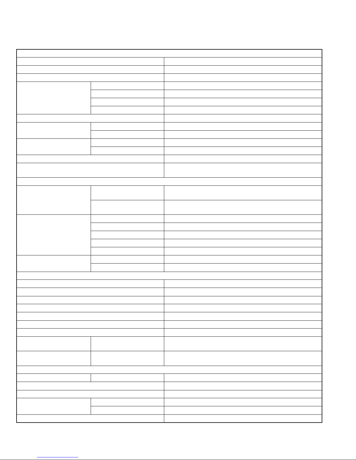
KD-AR390/KD-G340/KD-S25
Design and specifications are subject to change without notice.
AUDIO AMPLIFIER SECTION
Power Output 20 W RMS ×4 Channels at 4 Ωand < or = 1% THD+N
Signal-to-Noise Ratio 80 dBA (reference: 1 W into 4 Ω)
Load Impedance 4 Ω(4 Ωto 8 Ωallowance)
Tone Control Range Bass ±12 dB (60 Hz, 80 Hz, 100 Hz, 120 Hz)
Mid-range ±12 dB (500 Hz, 1.0 kHz, 1.5 kHz, 2.5 kHz)
Treble ±12 dB (7.5 kHz 10.0 kHz 12.5 kHz 15.0 kHz)
Q (band width) Q0.5 to Q2.0
Frequency Response 40 Hz to 20 000 Hz
Line-Out Level/Impedance KD-AR390 5.0 V/20 kΩload (full scale)
KD-G340/KD-S25 2.5 V/20 kΩload (full scale)
Subwoofer-Out Level/Impedance
KD-AR390 5.0 V /20 kΩload (full scale)
KD-G340/KD-S25 2.5 V/20 kΩload (full scale)
Output Impedance 1 kΩ
Other Terminal AUX (auxiliary) input jack CD changer jack Steering wheel remote
input (only for KD-AR390) Antenna
TUNER SECTION
Frequency Range FM
with channel interval set to 100 kHz or 200 kHz : 87.5 MHz to 107.9 MHz
with channel interval set to 50 kHz : 87.5 MHz to 108.0 MHz
AM with channel interval set to 10 kHz : 530 kHz to 1 710 kHz
with channel interval set to 9 kHz : 531 kHz to 1 602 kHz
FM Tuner Usable Sensitivity 11.3 dBf (1.0 µV/75 Ω)
50 dB Quieting Sensitivity 16.3 dBf (1.8 µV/75 Ω)
Alternate Channel Selectivity (400 kHz)
65 dB
Frequency Response 40 Hz to 15 000 Hz
Stereo Separation 35 dB
AM Tuner Sensitivity 20 µV
Selectivity 35 dB
CD PLAYER SECTION
Type Compact disc player
Signal Detection System Non-contact optical pickup (semiconductor laser)
Number of Channels 2 channels (stereo)
Frequency Response 5 Hz to 20 000 Hz
Dynamic Range 96 dB
Signal-to-Noise Ratio 98 dB
Wow and Flutter Less than measurable limit
MP3 Decoding Format
(MPEG1/2 Audio Layer 3)
Max. Bit Rate 320 kbps
WMA (Windows Media® Audio)
Decoding Format
Max. Bit Rate 192 kbps
GENERAL
Power Requirement Operating Voltage DC 14.4 V (11 V to 16 V allowance)
Grounding System Negative ground
Allowable Operating Temperature 0°C to +40°C (32°F to 104°F)
Dimensions (W
×
H
×
D) (approx.)
Installation Size 182 mm ×52 mm ×160 mm (7-3/16” ×2-1/16” ×6-5/16”)
Panel Size 188 mm ×58 mm ×6 mm (7-7/16” ×2-5/16” ×1/4”)
Mass 1.3 kg (2.9 lbs) (excluding accessories)


