manuals.online logo
Brands
  1. Home
  2. •
  3. Brands
  4. •
  5. JVC
  6. •
  7. Car Receiver
  8. •
  9. JVC KD-DV4207 Guide

JVC KD-DV4207 Guide

KD-DV4207
Installation/Connection Manual
Руководство по установке/подключению
GET0373-002A
[EE]
1205DTSMDTJEIN
EN, EE
1
ENGLISH
This unit is designed to operate on 12 V DC, NEGATIVE ground electrical systems. If your vehicle
does not have this system, a voltage inverter is required, which can be purchased at JVC IN-C R
ENTERT INMENT dealers.
WARNINGS
To prevent accidents and damage
• DO NOT install any unit in locations where;
– it may obstruct the steering wheel and gearshift lever operations.
– it may obstruct the operation of safety devices such as air bags.
– it may obstruct visibility.
• DO NOT operate the unit while driving.
• If you need to operate the unit while driving, be sure to look ahead carefully.
• The driver must not watch the monitor while driving.
If the parking brake is not engaged, “DRIVER MUST NOT WATCH THE MONITOR WHILE
DRIVING.” appears on the monitor, and no playback picture will be shown.
– This warning appears only when the parking brake wire is connected to the parking brake
system built in the car.
To prevent short circuits, we recommend that you disconnect the battery’s negative terminal and make all
electrical connections before installing the unit.
• Be sure to ground this unit to the car’s chassis again after installation.
Notes
• Replace the fuse with one of the specified rating. If the fuse blows frequently, consult your JVC IN-C R
ENTERT INMENT dealer.
• It is recommended to connect to the speakers with maximum power of more than 50 W (both at
the rear and at the front, with an impedance of 4 Ω to 8 Ω). If the maximum power is less than
50 W, change “ MP G IN” setting to prevent the speakers from being damaged (see page 24 of the
INSTRUCTIONS).
• To prevent short-circuit, cover the terminals of the UNUSED leads
with insulating tape.
• The heat sink becomes very hot after use. Be careful not to touch it
when removing this unit.
PRECAUTIONS on power supply and speaker
connections
• DO NOT connect the speaker leads of the power cord
to the car battery; otherwise, the unit will be seriously
damaged.
• BEFORE connecting the speaker leads of the power cord to the
speakers, check the speaker wiring in your car.
About sounds reproduced through the rear terminals
• Through the analog terminals (Speaker out/LINE OUT)
2-channel signal is emitted.
When playing a multi-channel encoded disc, multi-channel signals are downmixed. ( UDIO—
DOWN MIX: see page 26 of the INSTRUCTIONS.)
• Through DIGITAL OUT (optical)
Digital signals (Linear PCM, Dolby Digital*1, DTS*2, MPEG udio) are emitted through this terminal.
(For more details, see page 26 of the INSTRUCTIONS.)
To reproduce multi-channel sounds such as Dolby Digital and DTS, connect an amplifier or a decoder
compatible with these multi-channel sources to this terminal, and set “DIGIT L UDIO OUTPUT”
correctly. (See page 26 of the INSTRUCTIONS.)
*1 Manufactured under license from Dolby Laboratories. Dolby and the double-D symbol are trademarks of Dolby
Laboratories.
*2 “DTS” and “DTS 2.0 + Digital Out” are trademarks of Digital Theater Systems, Inc.
Heat sink
Радиатор
© 2005 Victor Company of Japan, Limited
РУССКИЙ
Это устройство разработа о для эксплуатации а 12 В постоянного напряжения с минусом на
массе. Если Ваш автомобиль е имеет этой системы, требуется и вертор апряже ия, который
может быть приобрете у дилера автомобил его специалиста JVC.
ПРЕДУПРЕЖДЕНИЯ
Предотвращение несчастных случаев и повреждений
• НЕ устанавливайте устройство в местах, где
– оно может помешать рулевому управлению и переключению передач.
–
оно может помешать функционированию средств безопасности, например, пневмоподушкам.
– может ухудшиться обзор.
• НЕ управляйте устройством во время вождения автомобиля.
• При необходимости управления устройством во время вождения автомобиля
внимательно следите за дорогой.
• Водителю не следует смотреть на монитор во время вождения.
Если стояночный тормоз не включен, на мониторе появляется сообщение “BОДИТЕЛЬ
НЕ ДОЛЖЕН СМОТРЕТЬ НА МОНИТОР ВО ВРЕМЯ ВОЖДЕНИЯ.” и изображение
воспроизведения отображаться не будет.
– Это предупреждение появляется только в том случае, если провод стояночного
тормоза подключен к стояночной тормозной системе автомобиля.
Для предотвраще ия коротких замыка ий мы рекоме дуем Вам отсоеди ить отрицатель ый
разъем аккумулятора и осуществить все подключе ия перед уста овкой устройства.
• После установки обязательно заземлите данное устройство на шасси автомобиля.
Примечания
• Заме яйте предохра итель другим предохра ителем указа ого класса. Если предохра итель
сгорает слишком часто, обратитесь к дилеру автомобил его специалиста JVC.
• Рекоме дуется подключать ди амики с максималь ой мощ остью более 50 Вт (к зад ей и
перед ей па ели устройства, с пол ым сопротивле ием от 4 Ω до 8 Ω). Если максималь ая
мощ ость ди амиков ме ее 50 Вт, перейдите в режим “AMP GAIN”, чтобы предотвратить их
поврежде ие (см. ИНСТРУКЦИИ ПО ЭКСПЛУАТАЦИИ а стр. 24).
• Для предотвраще ия короткого замыка ия заклейте НЕИСПОЛЬЗУЕМЫЕ ко цы изолирующей
ле той.
• Радиатор во время использова ия силь о агревается. Старайтесь его е трогать во время
удале ия устройства.
ПРЕДОСТЕРЕЖЕНИЯ по питанию и
подключению громкоговорителей
• НЕ подключайте провода громкоговорителей к
аккумулятору автомобиля, иначе устройство будет
повреждено.
• ПЕРЕД подключе ием проводов громкоговорителей
к кабелю пита ия громкоговорителя проверьте схему
соеди е ий громкоговорителей в Вашем автомобиле.
О звуках, воспроизводимых через задние терминалы
• Через аналоговые терминалы (выход для динамиков/LINE OUT)
Передается двухка аль ый сиг ал.
При воспроизведе ии диска с м огока аль ым кодирова ием выпол яется преобразова ие
м огока аль ых сиг алов. (AУДИО—СМEШEНИЕ: см. стр. 26 ИНСТРУКЦИЙ.)
• Через терминал DIGITAL OUT (оптический)
Через да ый терми ал передаются цифровые сиг алы (ли ей ый PCM, Dolby Digital*1, DTS*2,
MPEG Audio). (Более подроб ую и формацию см. а стр. 26 ИНСТРУКЦИЙ.)
Для воспроизведе ия м огока аль ого звука Dolby Digital и DTS подключите к да ому
терми алу усилитель или декодер, совместимый с этими м огока аль ыми источ иками и
уста овите правиль ое з аче ие для параметра “ЦИФPОВОЙ AУДИО ВЬІХОД”. (Cм. стр. 26
ИНСТРУКЦИЙ).
*1
Изготовле о по лице зии компа ии Dolby Laboratories. Долби и з ак в виде двой ой буквы D
являются товар ыми з аками компа ии Dolby Laboratories.
*2
“DTS” и “DTS 2.0 + Digital Out” являются торговыми марками Digital Theater Systems, Inc.
J
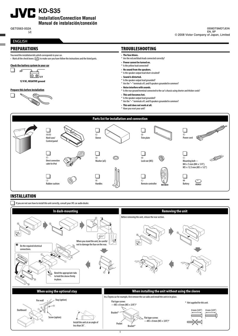
Rubber cushion
Рези овый чехол
F
Crimp connector
Обжим ой соеди итель
G
Washer (ø5)
Шайба (њ5)
H
Lock nut (M5)
Фиксирующая гайка (M5)
I
Mounting bolt (M5 × 20 mm)
Крепеж ый болт (M5 × 20 мм)
Parts list for installation and connection
If any item is missing, consult your JVC IN-C R ENTERT INMENT dealer immediately.
K
Handles
Рычаги
L
Remote controller
диcтa циo oго
yпpaвлe ия
M
Battery
Бaтapeйкa
Список деталей для установки и подключения
При отсутствии какого-либо элеме та емедле о свяжитесь с дилером автомобиль ых
аудиоустройств JVC.
A / B
Hard case/Control panel
Жесткий футляр/па ель
управле ия
C
Sleeve
Муфта
D
Trim plate
Декоратив ую па ель
E
Power cord
Кабель пита ия
Instal1-2_KD-DV4207[EE]f.indd 1Instal1-2_KD-DV4207[EE]f.indd 1 12/14/05 11:46:55 AM12/14/05 11:46:55 AM
2
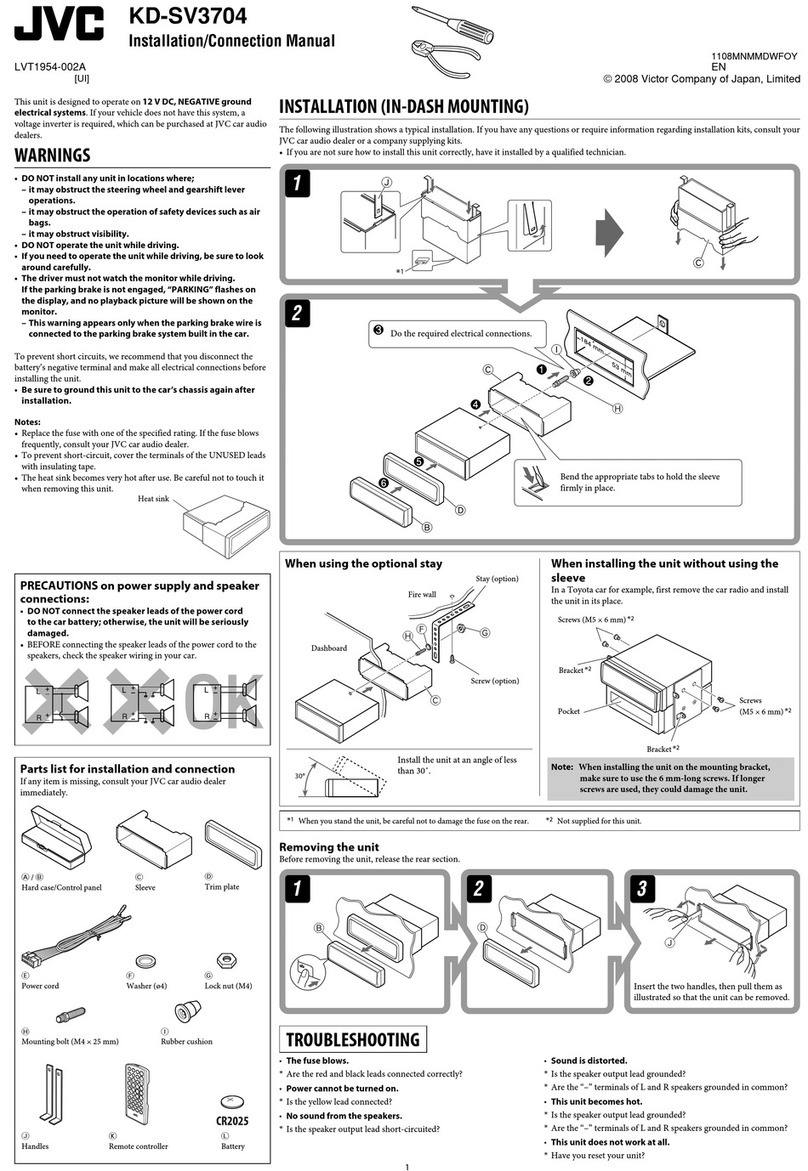
INSTALLATION (IN-DASH MOUNTING)
The following illustration shows a typical installation. If you have any questions or require information
regarding installation kits, consult your JVC IN-C R ENTERT INMENT dealer or a company supplying
kits.
• If you are not sure how to install this unit correctly, have it installed by a qualified technician.
Removing the unit
Before removing the unit, release the rear section.
УСТАНОВ А (УСТАНОВ А В ПРИБОРНУЮ ПАНЕЛЬ)
На следующих иллюстрациях показа а типовая уста овка. Если у Вас есть какие-либо вопросы,
касающиеся уста овки, обратитесь к Вашему дилеру автомобил его
специалиста JVC или в компа ию, поставляющую соответствующие при адлеж ости.
• Если Вы е з аете точ о, как следует уста авливать это устройство, обратитесь к
квалифицирова ому специалисту.
Do the required electrical connections.
Выпол ите еобходимые подключе ия
ко тактов, как показа о а оборот ой
сторо е этой и струкции.
Bend the appropriate tabs to hold the
sleeve firmly in place.
Отог ите соответствующие
фиксаторы, пред аз аче ые для
проч ой уста овки корпуса.
*3 When you stand the
unit, be careful not to
damage the fuse on the
rear.
*3 Уста авливайте
устройство таким
образом, чтобы
е повредить
предохра итель,
расположе ый
сзади.
When installing the unit without using the sleeve / При установке устройства без
использования муфты
In a Toyota car for example, first remove the car radio and install the unit in its place.
В автомобилях “Toyota”, апример, с ачала удалите автомобиль ую маг итолу, затем уста овите а ее место
это устройство.
When using the optional stay
/ При использовании
дополнительной стойки
Note When installing the unit on the mounting bracket, make sure to use the 8 mm-long screws. If longer
screws are used, they could damage the unit.
Примечание При уста овке устройства а крепеж ый кро штей , используйте только ви ты дли ой 8 мм.
При использова ии более дли ых ви тов мож о повредить устройство.
*4 Not supplied for this unit.
*4 Не входит в комплект поставки.
Screw (option)
Ви т (допол итель о)
Stay (option)
Стойка
(допол итель о)
Fire wall
Сте а
Dashboard
Прибор ая па ель
Install the unit at an angle of less than 30˚.
Уста овите устройство под углом ме ее 30°.
Bracket*4
Кро штей *4
Flat type screws (M5 × 8 mm)*4
Крепеж ые ви ты (M5 × 8 мм)*4
Pocket
Карма
Flat type screws (M5 × 8 mm)*4
Крепеж ые ви ты (M5 × 8 мм)*4
Bracket*4
Кро штей *4
Insert the two handles, then pull them as
illustrated so that the unit can be removed.
Вставьте два рычажка, затем потя ите их,
как показа о а рису ке, чтобы вы уть
устройство.
Удаление устройства
Перед удале ием устройства освободите зад юю часть.
TROUBLESHOOTING
• The fuse blows.
* re the red and black leads connected correctly?
• Power cannot be turned on.
* Is the yellow lead connected?
• No sound from the speakers.
* Is the speaker output lead short-circuited?
• Sound is distorted.
* Is the speaker output lead grounded?
* re the “–” terminals of L and R speakers grounded in common?
• Noise interfere with sounds.
* Is the rear ground terminal connected to the car’s chassis using shorter and thicker cords?
• Unit becomes hot.
* Is the speaker output lead grounded?
* re the “–” terminals of L and R speakers grounded in common?
• This unit does not work at all.
* Have you reset your unit?
BЫЯВЛЕНИЕ НЕИСПРАВНОСТЕЙ
• Сработал предохранитель.
* Правиль о ли подключе ы чер ый и крас ый провода?
• Питание не включается.
* Подключе ли желтый провод?
• Звук не выводится через громкоговорители.
* Нет ли короткого замыка ия а кабеле выхода громкоговорителей?
• Звук искажен.
* Заземле ли провод выхода громкоговорителей?
* Заземле ы ли разъемы “–” правого (R) и левого (L) громкоговорителей?
• Шум мешает звучанию.
* Соеди е ли аходящийся сзади зажим заземле ия с шасси автомобиля с помощью более
короткого и то кого ш уров?
• Устройство нагревается.
* Заземле ли провод выхода громкоговорителей?
* Заземле ы ли разъемы “–” правого (R) и левого (L) громкоговорителей?
• Приемник не работает.
* Выпол е а ли пере астройка прием ика?
Instal1-2_KD-DV4207[EE]f.indd 2Instal1-2_KD-DV4207[EE]f.indd 2 12/14/05 11:47:01 AM12/14/05 11:47:01 AM

ENGLISH РУССКИЙ
CConnecting the parking brake wire / Подключение провода
стояночного тормоза
When installing the monitor in a location where it can be seen by the driver
При уста овке мо итора в месте, вид ом водителю
When installing the monitor in a location where it cannot be seen by the driver
При уста овке мо итора в месте, е вид ом водителю
Connect the parking brake wire to metallic body or chassis or the car.
Подключить провод стояночного тор оза к еталлу корпуса или ходовой части авто обиля.
Connecting the crimp connector / Подключение обжимного разъема
D
Parking brake wire (light
green)
Провод стояночного
тор оза (зеленого цвета)
To metallic body or
chassis of the car
К еталлическо у
корпусу или шасси
авто обиля
Parking brake switch (inside the car)
Переключатель стояночного
тор оза (внутри авто обиля)
Parking brake
Стояночный тор оз
Parking brake wire (light green)
Провод стояночного тор оза (зеленого цвета)
3
B
To external components (see diagram )
К внешни устройства (с . схе у )
Light green
Зеленого цвета
VIDEO OUT
(see diagram / с . схе у )
DIGITAL OUT
(see diagram /
с . схе у )
A
*3 Not s pplied for this nit.
*3 Не входит в ко плект поставки.
To parking brake, metallic body or chassis of the car
К стояночно у тор озу, корпусу или ходовой части авто обиля
If your car is equipped with the ISO
connector /
Если автомобиль ос аще
разъемом ISO
• Connect the ISO connectors as ill strated.
• Подключите разъе ы ISO, как показано на рисунке.
For some VW/Audi or Opel (Vauxhall) automobile / Для екоторых автомобилей VW/Audi или Opel (Vauxhall)
Yo may need to modify the wiring of the s pplied power cord as ill strated.
• Contact yo r a thorized car dealer before installing this nit.
Воз ожно, потребуется из енить схе у соединений для прилагае ого шнура питания, как показано на рисунке.
• Перед установкой прие ника обратитесь к авторизованно у агенту по продажа авто обильных систе .
From the car body
От корпуса
авто обиля
ISO connector of the s pplied power cord
Разъе ISO шнура питания, входящего
в ко плект поставки
View from the lead side
Вид со стороны выводов
Original wiring /Исходная схе а соединений Modified wiring 1 /Преобразованная схе а соединений 1
Use modified wiring 2 if the nit does not t rn on.
Если прие ник не включается, используйте преобразованную схе у соединений
2
.
ISO connector
Разъе ISO
Y: Yellow
Желтый
R: Red
Красный
Modified wiring 2 /Преобразованная схема соединений 2
Before connecting: Check the wiring in the vehicle caref lly. Incorrect connection may ca se serio s
damage to this nit.
The leads of the power cord and those of the connector from the car body may be different in color.
1 C t the ISO connector.
2 Connect the colored leads of the power cord in the order specified in the ill stration below.
3 Connect the aerial cord.
4 Finally connect the wiring harness to the nit.
Connections without using the ISO connectors / Подключе ие без использова ия разъемов ISO
Перед началом подключений: Тщательно проверьте проводку в авто обиле.
Неправильное подключение ожет привести к серьезно у повреждению устройства.
Жилы силового кабеля и жилы соединителя от кузова авто обиля огут быть разного цвета.
1 Обрежьте разъе ISO.
2 Подсоедините цветные провода шнура питания в указанно ниже порядке.
3 Подключите кабель антенны.
4 В последнюю очередь подключите электропроводку к устройству.
15 A f se
Предохранитель 15 A
Black
Черный
Bl e with white stripe
Синий с белой полосой
Red
Красный
Yellow *2
Желтый*2
To metallic body or chassis of the car
К еталлическо у корпусу или шасси авто обиля
Ignition switch
Переключатель
зажигания
F se block
Блок предохранителя
To an accessory terminal in the f se block
К вспо огательно у разъе у в блоке предохранителя
To the remote lead of other eq ipment or power aerial if any (200 mA max.)
К удаленно у проводу другого оборудования или антенны ( акс. 200 А)
To a live terminal in the f se block connecting to the car battery (bypassing the
ignition switch) (constant 12 V)
К разъе у фазы в блоке предохранителя ( инуя блок зажигания) (постоянный 12 В)
*1 Not s pplied for this nit.
*1 Не входит в ко плект поставки.
Line o t (see diagram )
К выходу (с . схе у )
Rear gro nd terminal
Задний разъе зазе ления
*2
Before checking the operation of this nit prior to
installation, this lead m st be connected, otherwise power
cannot be t rned on.
*2 Перед проверкой работы устройства подключите этот
провод, иначе питание не включится.
Brown
Коричневый To cell lar phone system
К систе е сотового телефона
Left speaker (front)
Левый гро коговоритель
(передний)
Right speaker (front)
Правый гро коговоритель
(передний)
Left speaker (rear)
Левый гро коговоритель
(задний)
Right speaker (rear)
Правый
гро коговоритель
(задний)
P rple
Пурпурный
P rple with black stripe
Пурпурный с черной
полосой
Green
Зеленый
Green with black stripe
Зеленый с черной
полосой
Gray
Серый
Gray with black stripe
Серый с черной
полосой
White
Белый
White with black stripe
Белый с черной
полосой
Wire connecting the battery and the parking brake switch.
Подключить провод стояночного тор оза к этой точке.
Attach the parking brake wire to this point.
Провод, соединяющий акку улятор и
включатель стояночного тор оза.
Contact the metallic part of the crimp to the wires inside.
Присоедините еталлическую часть обжи ного
соединителя к находящи ся внутри провода .
Pinch the crimp firmly.
Плотно обожмите соединитель.
ELECTRICAL CONNECTIONS
ЭЛЕКТРИЧЕСКИЕ ПОДКЛЮЧЕНИЯ
Aerial connector
Разъе антенны
Instal3-4_KD-DV4207[EE]f.indd 3Instal3-4_KD-DV4207[EE]f.indd 3 12/22/05 11:44:21 AM12/22/05 11:44:21 AM
4
E
Other external component / Подключе ие в еш их устройств
CAUTION /
ПРЕДОСТЕРЕЖЕНИЕ:
• Before connecting the external
components, make s re that the nit is
t rned off.
• Перед подключение внешних
ко понентов убедитесь в то ,
что устройство выключено.
or
или
*8 Connecting cord s pplied for yo r
CD changer or DAB t ner
*8 Подключение кабеля, входящего
в ко плект поставки устройства
авто атической с ены ко пакт-
дисков или тюнера DAB
Connecting other external components / Подключе ие в еш их устройств
JVC CD changer
Устройство
автоматической сме ы
компакт-дисков JVC
JVC DAB tuner
Тю ер DAB JVC
External component
В еш ее
устройство
3.5 mm stereo mini pl g
Мини-разъе стерео-3,5
*10 AUX Inp t Adapter KS-U58 (not s pplied for this nit)
*10 Адаптер для подключения дополнительных устройств KS-U58
(не входит в ко плект поставки)
*9 Line Inp t Adapter KS-U57 (not s pplied for this nit)
*9 Ко уникационный адаптер KS-U57 (не входит в ко плект
поставки)
• Set “EXT IN” fo the exte nal input setting (See page 24 of the INSTRUCTIONS.) / Установите для внешнего входа значение “EXT IN” (Cм. ИНСТРУКЦИИ ПО ЭКСПЛУАТАЦИИ на стр. 24.)
Yo can connect these components in series as ill strated below. The iPod*7 or D. player can be
connected sing an interface adapter (not s pplied)—KS-PD100 (for iPod) or KS-PD500 (for
D. player).
• Set “CHANGER” fo the exte nal input setting (See page 24 of the INSTRUCTIONS.) / Установите для внешнего входа значение “CHANGER” (Cм. ИНСТРУКЦИИ ПО ЭКСПЛУАТАЦИИ на стр. 24.)
*7 iPod is a trademark of Apple
Comp ter, Inc., registered in the U.S.
and other co ntries.
*7 iPod является торговой
аркой Apple Computer, Inc.,
зарегистрированной в США и
других странах.
CD changer, DAB tuner, Apple iPod®, or JVC D. player / Устройство автоматической сме ы компакт-дисков, тю ер DAB, Apple iPod® или
проигрыватель JVC D.
G
F
CD changer jack
Разъе устройства
авто атической с ены
ко пакт-дисков
External component
В еш ее
устройство
Connecting the external amplifier / Подключе ие в еш их усилителей
Yo can connect an amplifier to pgrade yo r car stereo system.
• Connect the remote lead (bl e with white stripe) to the remote lead of the other eq ipment so that it
can be controlled thro gh this nit.
• Disconnect the speakers from this unit, connect them to the amplifier. Leave the speaker
leads of this unit unused.
Можно подключить усилители для обновления авто обильной стереосисте ы.
•
Подсоедините провод внешнего устройства (синий с белой полосой) к проводу внешнего
устройства другого оборудования так, чтобы и ожно было управлять с этого устройства.
• Отсоеди ите громкоговорители от да ого устройства, подключите их к усилителю.
Оставьте провода громкоговорителей да ого устройства еиспользова ыми.
Rear speakers
Задние
гро коговорители
JVC Amplifier
JVC-усилитель
Remote lead
Провод внешнего устройства
Y-connector (not s pplied for this nit)
Разъе Y (не входит в ко плект поставки)
Remote lead (Bl e with white stripe)
Провод внешнего устройства (Синий с белой полосой)
To the remote lead of other
eq ipment or power aerial if any
К удаленно у проводу другого
оборудования или антенны
Front speakers (see diagram )
Передние гро коговорители (с . схе у )
Rear speakers
Задние гро коговорители
*6 C t the rear speaker leads of the car’s ISO connector
and connect them to the amplifier.
*6
Отрежьте провода задних гро коговорителей
разъе а ISO и подсоеди ните их к усилителю.
*5
Signal cord (not s pplied for this nit)
*5 Кабель сигнала (не входит в ко плект
поставки)
Required connections for DVD playback / Необходимые подключения для воспроизведения DVD
A dio/video control amplifier or the decoder compatible with the m ltichannel
digital so rces
Управляющий усилитель аудио/видео декодера, сов ести ый с
ногоканальны и цифровы и источника и
KV-MR9010
9-INCH WIDESCREEN MONITOR (not s pplied)
9-ДЮЙМОВЫЙ ШИРОКОЭКРАННЫЙ МОНИТОР
(не входит в ко плект поставки)
Digital optical cable (not s pplied)
Цифровой оптический кабель
(не входит в ко плект поставки)
DIGITAL OUT
See “Abo t so nds reprod ced
thro gh the rear terminals.”
См. “О звуках,
воспроизводимых через
задние терминалы .
Apple iPod
(separately p rchased)
Apple iPod
(продается отдельно)
JVC D. player (separately
p rchased)
Проигрыватель JVC D.
(продается отдельно)
JVC DAB tuner
Тю ер DAB JVC
CD changer jack
Разъе устройства авто атической
с ены ко пакт-дисков
CD changer jack
Разъе устройства авто атической
с ены ко пакт-дисков
Apple iPod
(separately p rchased)
Apple iPod
(продается отдельно)
JVC D. player (separately
p rchased)
Проигрыватель JVC D.
(продается отдельно)
Video cord (not s pplied)
Видеошнур (не входит в ко плект поставки)
*4 Firmly attach the gro nd wire to the metallic
body or to the chassis of the car—to the place not
coated with paint (if coated with paint, remove
the paint before attaching the wire). Fail re to do
so may ca se damage to the nit.
*4 Плотно прикрепите зазе ляющий провод
к еталлическо у кузову или шасси
авто обиля—в есте, не покрыто
краской (если оно покрыто краской,
удалите краску перед те , как прикреплять
провод). Невыполнение этого требования
ожет привести к повреждению данного
устройства.
or
или
or
или
Эти внешние устройства ожно подключать параллельно, как показано на рисунке.
Проигрыватель iPod*7 или D. ожно подключить с по ощью интерфейсного адаптера (не
входит в ко плект поставки)—KS-PD100 (для iPod) или KS-PD500 (для проигрывателя D.).
JVC CD changer
Устройство
автоматической сме ы
компакт-дисков JVC
Instal3-4_KD-DV4207[EE]f.indd 4Instal3-4_KD-DV4207[EE]f.indd 4 12/14/05 11:56:07 AM12/14/05 11:56:07 AM

Other JVC Car Receiver manuals

JVC KD-R775S User manual

JVC

JVC KD-R775S User manual

JVC KD-S52 User manual

JVC

JVC KD-S52 User manual

JVC KD-MX2800R User manual

JVC

JVC KD-MX2800R User manual

JVC GET0655-001B Guide

JVC

JVC GET0655-001B Guide

JVC KD-R900 User manual

JVC

JVC KD-R900 User manual

JVC KD-LH811 User manual

JVC

JVC KD-LH811 User manual

JVC KD-R728BT User manual

JVC

JVC KD-R728BT User manual

JVC KD-HDR70 User manual

JVC

JVC KD-HDR70 User manual

JVC GET0564-006A User manual

JVC

JVC GET0564-006A User manual

JVC EXAD KD-NX901 User manual

JVC

JVC EXAD KD-NX901 User manual

JVC KD-ADV49 - DVD Player With LCD monitor User manual

JVC

JVC KD-ADV49 - DVD Player With LCD monitor User manual

JVC EXAD KD-LHX552 User manual

JVC

JVC EXAD KD-LHX552 User manual

JVC KS-FX7 User manual

JVC

JVC KS-FX7 User manual

JVC KD-AR270 - Radio / CD User manual

JVC

JVC KD-AR270 - Radio / CD User manual

JVC KD-R601 Guide

JVC

JVC KD-R601 Guide

JVC KD-LX110R User manual

JVC

JVC KD-LX110R User manual

JVC KD-G821 User manual

JVC

JVC KD-G821 User manual

JVC KD-PDR31 Guide

JVC

JVC KD-PDR31 Guide

JVC KW-NSX1 Guide

JVC

JVC KW-NSX1 Guide

JVC KD-AR760 - Arsenal CD Receiver User manual

JVC

JVC KD-AR760 - Arsenal CD Receiver User manual

JVC KD-DV4202 User manual

JVC

JVC KD-DV4202 User manual

JVC KD-LH7R User manual

JVC

JVC KD-LH7R User manual

JVC KD-SX925R User manual

JVC

JVC KD-SX925R User manual

JVC KD-R901 User manual

JVC

JVC KD-R901 User manual

Popular Car Receiver manuals by other brands

Jensen HD5313 Installation and operation manual

Jensen

Jensen HD5313 Installation and operation manual

Panasonic CQ-DF701W operating instructions

Panasonic

Panasonic CQ-DF701W operating instructions

Sony XR-CA600V operating instructions

Sony

Sony XR-CA600V operating instructions

Panasonic CQDF402U - AUTO RADIO/CD DECK operating instructions

Panasonic

Panasonic CQDF402U - AUTO RADIO/CD DECK operating instructions

Sanyo FXR-100LD Service manual

Sanyo

Sanyo FXR-100LD Service manual

Kenwood KVT-915DVD instruction manual

Kenwood

Kenwood KVT-915DVD instruction manual

Chrysler Uconnet Touch user manual

Chrysler

Chrysler Uconnet Touch user manual

Sony XR-CA300 - Fm-am Cassette Car Stereo operating instructions

Sony

Sony XR-CA300 - Fm-am Cassette Car Stereo operating instructions

Panasonic CQC5110U - AUTO RADIO/CD DECK operating instructions

Panasonic

Panasonic CQC5110U - AUTO RADIO/CD DECK operating instructions

Denon CEOL RCD-N10 owner's manual

Denon

Denon CEOL RCD-N10 owner's manual

Alpine CDE-9886R owner's manual

Alpine

Alpine CDE-9886R owner's manual

Pioneer DEH-6150BT installation manual

Pioneer

Pioneer DEH-6150BT installation manual

Clarion VRX775VD Service manual

Clarion

Clarion VRX775VD Service manual

Furrion dv5600 instruction manual

Furrion

Furrion dv5600 instruction manual

Pioneer P1280 - CDX CD Changer owner's manual

Pioneer

Pioneer P1280 - CDX CD Changer owner's manual

Pioneer DEH-2220UB Operation manual

Pioneer

Pioneer DEH-2220UB Operation manual

Alpine CDA-9833R owner's manual

Alpine

Alpine CDA-9833R owner's manual

Biketronics BT1000 installation instructions

Biketronics

Biketronics BT1000 installation instructions

manuals.online logo
manuals.online logoBrands
  • About & Mission
  • Contact us
  • Privacy Policy
  • Terms and Conditions

Copyright 2025 Manuals.Online. All Rights Reserved.