JVC KD-LH915 Guide

KD-LH915
Installation/Connection Manual
°“√µ‘¥µ—Èß/§ŸË¡◊Õ°“√µ‘¥µ—Èß
GET0273-004A
[U/UH]
0105DTSMDTJEIN
EN, TH
J
Handles
§—π∫—ß§—∫
F
Washer (ø5)
ª√–‡°Áπ«ß·À«π (ø5)
G
Lock nut (M5)
πÕµ≈ÁÕ§ (M5)
H
Mounting bolt (M5 x 20 mm)
≈—°µ‘¥ (M5 x 20 ¡‘≈≈‘‡¡µ√)
I
Rubber cushion
¬“ß°—π°√–·∑°
A / B
Hard case/Control panel
≈—ß∫√√®ÿ/ÀπÈ“ª—¥
C
Sleeve
ª≈Õ°ÀÿÈ¡
D
Trim plate
·ºËπ‚≈À–¢Õ∫·µËß
E
Power cord
“¬‡§‡∫‘≈°”≈—ß
1
ENGLISH
This receiver is designed to operate on 12 V DC, NEGATIVE ground electrical systems. If
your vehicle does not have this system, a voltage inverter is required, which can be purchased
at JVC car audio dealers.
Parts list for installation and connection
The following parts are provided for this receiver.
After checking them, please set them correctly.
INSTALLATION
(IN-DASH MOUNTING)
The following illustration shows a typical installation. If you have any questions or require
information regarding installation kits, consult your JVC car audio dealer or a company supplying
kits.
• If you are not sure how to install this receiver correctly, have it installed by a qualified
technician.
K
Remote controller
√’‚¡µ§Õπ‚∑√≈
L
Battery
·∫µ‡µÕ√
Removing the receiver
Before removing the receiver, release the rear section.
*1 When you stand the receiver, be careful not to damage the fuse on the rear.
*1 ‡¡◊ËÕ§ÿ≥µ—Èß™ÿ¥ª√–°Õ∫¢÷Èπ √–«—ßլ˓∑”„ÀÈø‘«Ï∫√‘‡«≥Ë«π∑È“¬‡’¬À“¬
*2 Fit the protrusions outside the receiver.
*2 µ‘¥µ—Èß≈Ë«π∑’ˬ◊ËπÕÕ°¡“∑’˥ȓππÕ°‡§√◊ËÕß
M
CD-ROM
(Image Converter: Wide Ver 1.2)
CD-ROM
(Image Converter: Wide Ver 1.2)
Do the required electrical
connections.
µËÕ“¬‰øµ“¡∑’˰”À𥉫È∑—ÈßÀ¡¥
Bend the appropriate tabs
to hold the sleeve firmly in
place.
ßÕ·ºËπ‡æ◊ËÕ¬÷¥ª≈Õ°„ÀȵËÕ°—π‡¢È“∑’Ë
Insert the two handles, then pull them
as illustrated so that the receiver can
be removed.
„˧—π∫—ß§—∫ 2 Õ—π≈ß„π√ËÕß”À√—∫„™Èæ—π≈«¥
¥—ß¿“æ ®“°π—Èπ „Àȇ≈◊ËÕπ™ÿ¥ª√–°Õ∫ÕÕ°
„π¢≥–∑’˧ËÕ¬ Ê¥÷ß§—π∫—ß§—∫∑—Èß Õß Õ—πÕÕ°®“°°—π
‰∑¬
™ÿ¥¢¢ª√–°Õ∫π’ȉ¥È√—∫°“√ÕÕ°·∫∫¡“‡æ◊ËÕ„™Èß“π°—∫√–∫∫ °√–·‰øøÈ““¬¥‘π¢—È«≈∫°√–·µ√ß 12 ‚«≈∑Ï À“°√∂¬πµÏ¢Õß§ÿ≥‰¡Ë‰
¥È„™È√–∫∫π’È µÈÕß„™È‡§√◊ËÕß·ª≈ß°√–·‰ø™Ë«¬ ´÷Ëß“¡“√∂À“´◊ÈÕ‰¥È®“°√È“π¢“¬‡§√◊ËÕ߇’¬ß√∂¬πµÏ JVC
√“¬°“√Ë«πª√–°Õ∫”À√—∫µ‘¥µ—Èß·≈–‡™◊ËÕ¡µËÕ°—π
«πª√–°Õ∫µËÕ‰ªπ’È„ÀÈ¡“°—∫™ÿ¥ª√–°Õ∫π’È À≈—ß®“°µ√«®Õ∫·≈È« ª√—∫µ—È߇§√◊ËÕß„ÀÈ∂Ÿ°µÈÕß
°“√µ‘¥µ—Èß
(°“√ª√–°Õ∫·ºßÀπÈ“ª—∑¡Ï‡¢È“)
¿“æµ—«Õ¬Ë“ßµËÕ‰ªπ’È·¥ß∂÷ß°“√µ‘¥µ—Èß·∫∫∑—Ë«‰ª À“°§ÿ≥¡’ª—≠À“À√◊ÕµÈÕß°“√¢ÈÕ¡Ÿ≈‡°’ˬ«°—∫™ÿ¥µ‘¥µ—Èß °√ÿ≥“ª√÷°…“°
∫ºŸÈ¢“¬‡§√◊ËÕ߇’¬ß√∂¬πµÏ JVC ¢Õß∑Ë“πÀ√◊Õ∫√‘…—
•
™ÿ¥ª√–°Õ∫ ∂È“§ÿ≥‰¡Ë·πË„®«Ë“µ‘¥µ—Èß™ÿ¥ª√–°Õ∫π’È∂Ÿ°µÈÕßÀ√◊Õ‰¡Ë „ÀÈÀ“™Ë“ߺŸÈ‡™’ˬ«™“≠‡ªÁπºŸÈµ‘¥µ—Èß
°“√∂Õ¥™ÿ¥ª√–°Õ∫
°ËÕπ®–∂Õ¥™ÿ¥ª√–°Õ∫ „ÀȪ≈¥ÀπÈ“µ—¥Ë«π∑È“¬°ËÕπ
Instal1-2_KD-LH915_002A.indd 2 12/22/04 5:01:50 PM

When installing the receiver without using the sleeve / ‡¡◊ËÕµ‘¥µ—Èß™ÿ¥ª√–°Õ∫‚¥¬‰¡Ë„™Èª≈Õ°ÀÿÈ¡
In a Toyota for example, first remove the car radio and install the receiver in its place.
µ—«Õ¬Ë“߇™Ëπ „π√∂¬πµÏ‚µ‚¬µÈ“ „ÀÈ∂Õ¥«‘∑¬ÿµ‘¥√∂¬πµÏÕÕ°°ËÕπ·≈–µ‘¥µ—Èß™ÿ¥ª√–°Õ∫π’ȇ¢È“‰ª·∑π
When using the optional stay / ‡¡◊ËÕ„™Èµ—«¬÷¥·∫∫‡≈◊Õ°‰¥â
Note : When installing the receiver on the mounting bracket, make sure to use the 8 mm-long screws. If
longer screws are used, they could damage the receiver.
À¡“¬‡Àµ : ‡¡◊ËÕµ‘¥µ—Èß™ÿ¥ª√–°Õ∫≈ß„π·∑Ëπ√Õß√—∫‰«È „ÀÈ„™È°√Ÿ¬“«¢π“¥ 8 ¡‘≈≈‘‡¡µ√ ∂È“„™È°√Ÿ¬“«°«Ë“π’ÈÕ“®∑”„ÀÈ™ÿ¥ª√–°Õ∫‡’¬À“¬‰¥ô
Bracket*3
·∑Ëπ√Õß√—∫*3
*3 Not included for this receiver.
*3
‰¡Ë‰¥È„ÀÈ¡“°—∫™ÿ¥ª√–°Õ∫π
Flat type screws (M5 x 8 mm)*3
°√ŸÀ—«‡√’¬∫ (M5 x 8 ¡‘≈≈‘‡¡µ√)*3
Pocket
°–‡ª“–
Flat type screws (M5 x 8 mm)*3
°√ŸÀ—«‡√’¬∫ (M5 x 8 ¡‘≈≈‘‡¡µ√)*3
Install the receiver at an angle of less
than 30˚.
µ‘¥µ—Èß™ÿ¥ª√–°Õ∫∑’Ë¡ÿ¡µË”°«Ë“ 30 Õß»“
Heat sink
·ºËπ√–∫“¬§«“¡√ÈÕπ
2
TROUBLESHOOTING
• The fuse blows.
* Are the red and black leads connected correctly?
• Power cannot be turned on.
* Is the yellow lead connected?
• No sound from the speakers.
* Is the speaker output lead short-circuited?
• Sound is distorted.
* Is the speaker output lead grounded?
* Are the “–” terminals of L and R speakers grounded in common?
• Noise interfere with sounds.
* Is the rear ground terminal connected to the car’s chassis using shorter and thicker cords?
• Receiver becomes hot.
* Is the speaker output lead grounded?
* Are the “–” terminals of L and R speakers grounded in common?
• This receiver does not work at all.
* Have you reset your receiver?
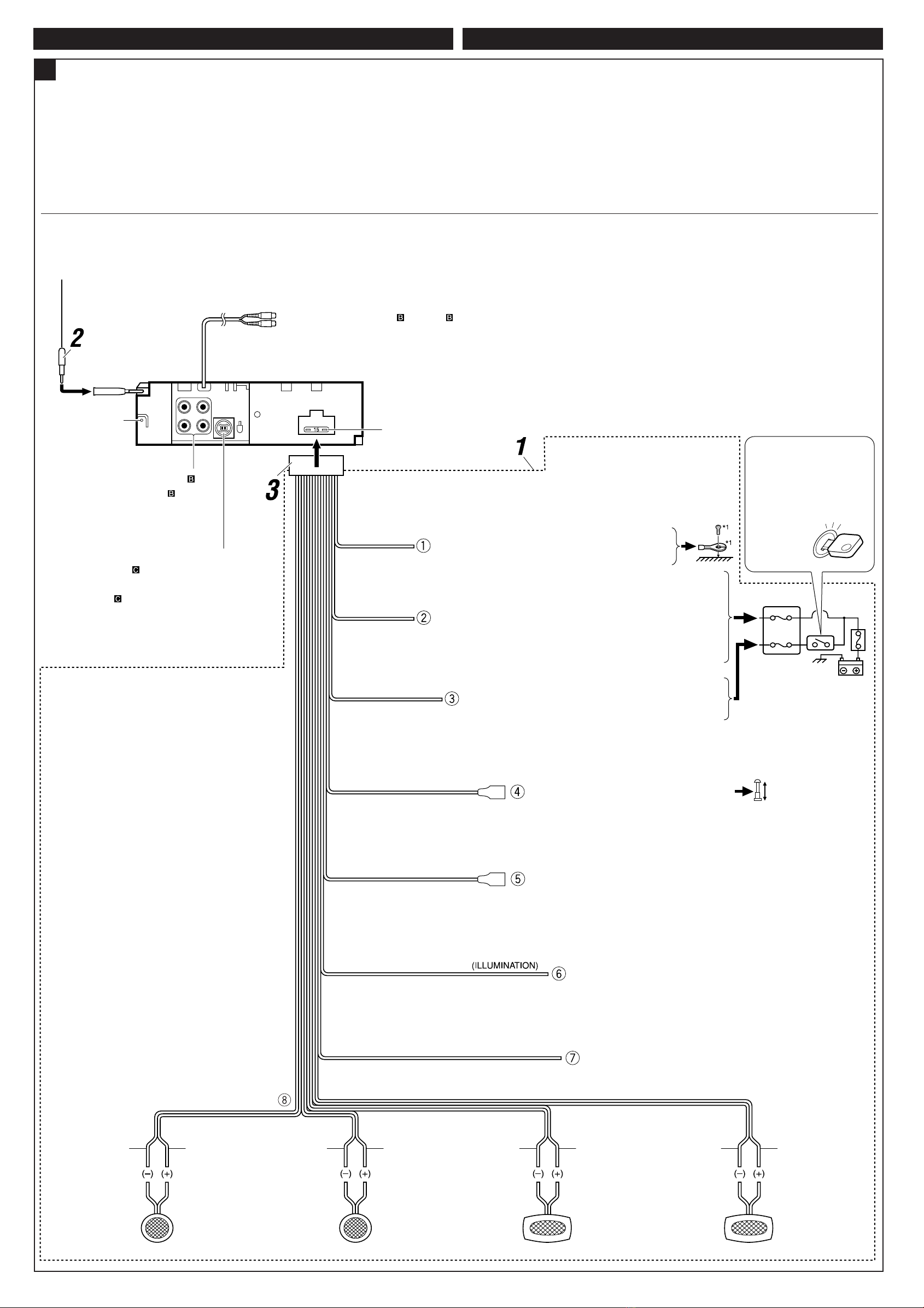
ELECTRICAL CONNECTIONS
To prevent short circuits, we recommend that you disconnect the battery’s negative terminal and
make all electrical connections before installing the receiver.
• Be sure to ground this receiver to the car’s chassis again after installation.
Notes:
• Replace the fuse with one of the specified rating. If the fuse blows frequently, consult your JVC
car audio dealer.
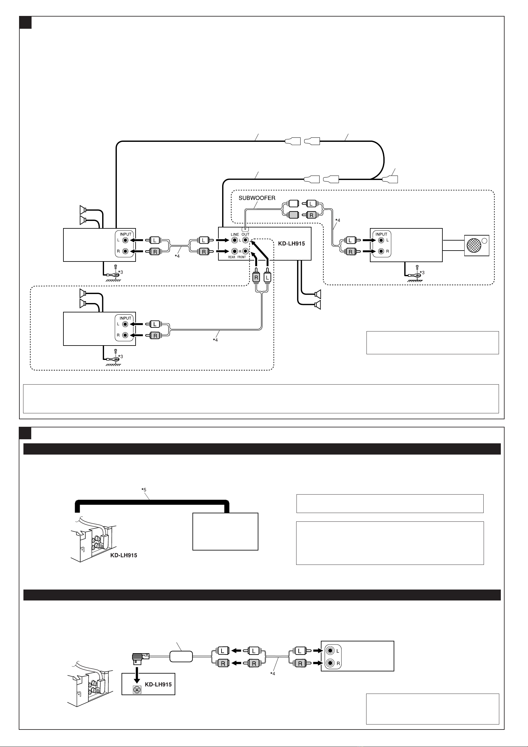
• It is recommended to connect to the speakers with maximum power of more than 50 W (both
at the rear and at the front, with an impedance of 4 Ω to 8 Ω). If the maximum power is less
than 50 W, change “Amp Gain” setting to prevent the speakers from being damaged (see page
32 of the INSTRUCTIONS).
• To prevent short-circuit, cover the terminals of the UNUSED leads with insulating tape.
• The heat sink becomes very hot after use. Be careful not to touch it when removing this
receiver.
PRECAUTIONS on power supply and speaker connections:
• DO NOT connect the speaker leads of the power cord to the car battery; otherwise,
the receiver will be seriously damaged.
• BEFORE connecting the speaker leads of the power cord to the speakers, check the
speaker wiring in your car.
Bracket*3
·∑Ëπ√Õß√—∫*3
Dashboard
·ºßÀπÈ“ª—∑¡á
Fire wall
ºπ—ß°—π‰ø Stay (option)
µ—«¬÷¥ (‡≈◊Õ°‰¥È)
Screw (option)
°√Ÿ (‡≈◊Õ°‰¥È)
°“√µ√«®Õ∫ª—≠À“¢—¥¢ÈÕß
• ø‘«ú¢“¥
* ¡’°“√‡™◊ËÕ¡“¬µ–°—Ë«’¥”·≈–’·¥ßլ˓ß∂Ÿ°µÈÕßÀ√◊Õ‰¡ò
• ‰¡Ë“¡“√∂‡ª‘¥‡§√◊ËÕ߉¥È
* ¡’°“√‡™◊ËÕ¡“¬µ–°—Ë«’‡À≈◊ÕßÀ√◊Õ‰¡ò
• ‰¡Ë¡’‡’¬ßÕÕ°®“°≈”‚æß
* “¬µ–°—˫˫π∑’ËÕÕ°∑“ß≈”‚æß‡°‘¥‰øøÈ“≈—¥«ß®√À√◊Õ‰¡Ë
• ‡’¬ß‡æ’Ȭπ
* “¬µ–°—˫˫π∑’ËÕÕ°∑“ß≈”‚æßµËÕ≈ߥ‘πÀ√◊Õ‰¡Ë
* “¬¢—È«≈∫¢Õß≈”‚æß¥È“π´È“¬ (L) ·≈–¢«“ (R) µËÕ≈ߥ‘πµ“¡ª°µ‘À√◊Õ‰¡Ë
• ‡’¬ß√∫°«π
* ¡’°“√„™È“¬—ÈπÊ À√◊ÕÀπ“Ê µËÕ®“°‡§√◊ËÕßò«π∑’˵‘¥µ—Èß ‰«È∫πæ◊Èπ¥È“πÀ≈—ß°—∫µ—«∂—ß√∂¬πµÏÀ√◊Õ‰¡Ë
• ™ÿ¥ª√–°Õ∫√ÈÕπ¢÷Èπ
* “¬µ–°—˫˫π∑’ËÕÕ°∑“ß≈”‚æßµËÕ≈ߥ‘πÀ√◊Õ‰¡Ë
* “¬¢—È«≈∫¢Õß≈”‚æß¥È“π´È“¬ (L) ·≈–¢«“ (R) µËÕ≈ߥ‘πµ“¡ª°µ‘À√◊Õ‰¡Ë
• ‡§√◊ËÕß√—∫π’È∑”ß“π‰¡
* ∑Ë“π‰¥Èµ—È߇§√◊ËÕß„À¡ËÀÈ√◊Õ¬—ß
¢ÈÕ§«√√–«—ß”À√—∫°“√µËÕ·À≈Ë߮˓¬°”≈—ß·≈–≈”‚æß:
• լ˓µËÕ“¬µ–°—Ë«‡§‡∫‘≈°”≈—ߢÕß≈”‚æß‡¢È“°—∫·∫µ‡µÕ√’Ë√∂¬πµÏ ¡‘©–π—Èπ ™ÿ¥ª√–°Õ∫®–‰¥È√—∫§«“¡‡’¬À“¬¡“°
• °ËÕπ∑’Ë®–µËÕ“¬µ–°—Ë«‡§‡∫‘≈°”≈—ߢÕß≈”‚æß‡¢È“°—∫≈”‚æß „Àȵ√«®Õ∫°“√‡¥‘𓬉ø≈”‚æß„π√∂¢Õß§ÿ≥„Àȇ√’¬∫√ÈÕ¬‡’¬°ËÕπ
°“√‡™◊ËÕ¡‚¥¬„™È‰øøÈ“
‡æ◊ËÕªÈÕß°—π°“√‡°‘¥‰øøÈ“≈—¥«ß®√ ¢Õ·π–π”„ÀȪ≈¥¢—È«·∫µ‡µÕ√’Ë≈∫ÕÕ° ·≈È«®÷ßµËÕ“¬‰ø°ËÕ𵑥µ—È߇§√◊ËÕß
• µ√«®Õ∫„ÀÈ·πË„®«Ë“‰¥È‡¥‘𓬥‘πµËÕ√–À«Ë“߇§√◊ËÕß°—∫µ—«∂—ß √∂¬πµÏ„À¡Ë·≈È«À≈—ß®“°µ‘¥µ—Èß
À¡“¬‡Àµÿ:
• „™Èæ‘°—¥®”‡æ“–·∑πø‘« À“°ø‘«Ï¢“¥∫ËÕ¬ „ÀȪ√÷°…“√È“ π¢“¬‡§√◊ËÕ߇’¬ß√∂¬πµÏ JVC
• ¢Õ·π–π”„ÀȵËÕ≈”‚æß ∑’Ë¡’°”≈—ߢ—∫ßÿ¥‡°‘π°«Ë“ 50 W (∑—ÈߥȓπÀπÈ“·≈–¥È“πÀ≈—ß ¡’§Ë“§«“¡µÈ“π∑“π 4 Ω ∂÷ß 8 Ω)
∂È“°”≈—ߢ—∫µË”°«Ë“ 50 W „Àȇª≈’ˬπ§Ë“ “Amp Gain” ‡æ◊ËÕªÈÕß°—π‰¡Ë„ÀÈ≈”‚æß™”√ÿ¥ (¥ŸÀπÈ“ 32 §”·π–π”)
• °“√ªÈÕß°—π°“√≈—¥«ß®√ ®–µÈÕßæ—π¢—È«“¬µ–°—Ë« ∑’ˉ¡Ë„™È·≈È«¥È«¬‡∑ ªæ—𓬉ø
• ·ºËπ√–∫“¬§«“¡√ÈÕπ®–√ÈÕπ¡“°À≈—ß®“°„™È √–¡—¥√–«—ßլ˓‰ª —¡º—‡¡◊ËÕ∂Õ¥™ÿ¥ª√–°Õ∫π’ô
Fit the receiver into the mounting sleeve by using four corners of the trim plate.
• DO NOT press the panel (shaded in the illustration).
µ‘¥µ—È߇§√◊ËÕ߇¢È“„πª≈Õ°ÀÿÈ¡ „Àȵ√ß°—∫¢Õ∫¢Õß·ºËπ∑’˵—¥·µËß∑—Èß’Ë
• ÀÈ“¡¥—π∑’Ë·ºß§«∫§ÿ¡ (Ë«π∑’Ë√–∫“¬’„π√Ÿª)
Caution when installing / ¢ÈÕ§«√√–«—߇¡◊ËÕ∑”°“√µ‘¥µ—Èß
Instal1-2_KD-LH915_002A.indd 3 12/22/04 5:01:55 PM

ATypical Connections / °“√‡™◊ËÕ¡µËÕ·∫∫ª°µ‘
Before connecting: Check the wiring in the vehicle carefully. Incorrect connection may cause
serious damage to this receiver.
The leads of the power cord and those of the connector from the car body may be different in
color.
1 Connect the colored leads of the power cord in the order specified in the illustration below.
2 Connect the antenna cord.
3 Finally connect the wiring harness to the receiver.
ENGLISH
3
SUBWOOFER (see diagram / ¥Ÿ·ºπ¿Ÿ¡ )
Rear ground
terminal
®ÿ¥‡™◊ËÕ¡µËÕ“¬¥‘
π¥È“πÀ≈—ß
Line out (see diagram )
“¬ÕÕ° (¥Ÿ·ºπ¿Ÿ¡ )
To CD changer or another external component
(see diagram )
™ËÕ߇’¬∫µËÕ¢Õ߇§√◊ËÕ߇≈Ëπ´’¥ CD ≈À–Õÿª°√≥Ï¿“¬πÕ°
(¥Ÿ·ºπ¿Ÿ¡ )
*2
Before checking the operation of this receiver
prior to installation, this lead must be connected,
otherwise power cannot be turned on.
*2
°ËÕπ°“√µ√«®Õ∫°“√∑”ß“π¢Õß™ÿ¥ª√–°Õ∫π’ȰËÕπ∑’Ë®–µ‘¥µ—Èß
µÈÕßµËÕ“¬µ–°—Ë«π’ȰËÕπ ¡‘©–π—Èπ®–‰¡“¡“√∂‡ª‘¥‡§√◊ËÕ߉¥
White with black
stripe
¢“«·∂∫¥”
White
’¢“«
Gray with black stripe
’‡∑“·∂∫¥”
Left speaker (front)
≈”‚æß´È“¬ (ÀπÈ“)
Gray
’‡∑“
Right speaker (front)
≈”‚æß¢«“ (ÀπÈ“)
Green with black stripe
’‡¢’¬«·∂∫¥”
Brown
πÈ”µ“≈
Orange with white stripe
’È¡·∂∫¢“«
Blue with white stripe
πÈ”‡ß‘π≈“¬¢“«
Red
¥ß
Yellow*2
’‡À≈◊Õß*2
Black
¥”
15 A fuse
ø‘«Ï¢π“¥ 15 A
*1 Not included for this receiver
*1 ‰¡Ë‰¥È„ÀÈ¡“°—∫™ÿ¥ª√–°Õ∫π Ignition switch
«‘∑™Ï®ÿ¥√–‡∫‘¥
To metallic body or chassis of the car
µËÕ°—∫‚§√ß‚≈À–À√◊Õ‡™´‘¢Õß√∂¬πµú
To a live terminal in the fuse block connecting to the car battery
(bypassing the ignition switch) (constant 12 V)
µËÕ°—∫¢—È«∑’Ë¡’°√–·‰øøÈ“„π·ºßø‘«Ï ´÷ËßµËÕ°—∫·∫µ‡µÕ√’Ë√∂¬πµ
(‚¥¬‰¡ËµÈÕß„™È«‘∑™Ï®ÿ¥√–‡∫‘¥) (12 ‚«≈∑ϧß∑’Ë)
To an accessory terminal in the fuse block
µËÕ°—∫¢—È«ò«πª√–°Õ∫„π·ºßø‘«
To the remote lead of other equipment (200 mA max.)
µËÕ‡¢È“°—∫Õª°√≥ÏÕË◊π (¢π“¥Ÿß¸¥ 200 mA)
Fuse block
·ºßø‘«
To car light control switch
«‘µ´Ï§«∫§ÿ¡‰ø¢Õß√∂¬πµ√Ï
To cellular phone system
µËÕ°—∫‚∑√»—æ∑χ§≈◊ËÕπ∑
Purple
’¡Ë«ß
Right speaker (rear)
≈”‚æß¢«“ (À≈—ß)
Purple with black stripe
’¡Ë«ß·∂∫¥”
Left speaker (rear)
≈”‚æß´È“¬ (À≈—ß)
Green
’‡¢’¬«
°ËÕ•∑”°“•‡™•ËÕ¡µËÕ: µ•«®†Õ•°“•‡¥‘•†“¬‰ø„•••¬•µÏլ˓ߕ–¡—¥•–«—լ˓„ÀȺ‘¥æ•“¥„•°“•‡™•ËÕ¡µËÕ™ÿ¥ª•–°Õ•™ÿ¥•’
°“•‡™•ËÕ¡µËÕº‘¥æ•“¥Õ“®∑”„Àȇ°‘¥§«“¡‡’¬À“¬•È“¬·•ß°—•™ÿ¥ª•–
°Õ••’ȉ¥È“•µ–°—Ë«¢Õ߆“¬‰ø ·•–¢ÕßÕÿª°••ϵËÕ‡™•ËÕ¡®“°µ—«• ß••Õ“®¡’ ∑’ˉ¡Ë‡À¡•Õ•°—•
1 µËÕ“¬‰ø’µ“¡≈”¥—∫∑’Ë√–∫ÿ„π√Ÿª¥È“π≈Ë“ß
2 ‡™◊ËÕ¡µËÕ°—∫“¬Õ“°“»
3 ÿ¥∑È“¬ µËËÕò«π§«∫§ÿ¡°“√‡¥‘𓬉ø‡¢È“°—∫™ÿ¥ª√–°Õ∫™ÿ¥π’È
To automatic antenna if any (250 mA max.)
‡“Õ“°“»‰øøÈ“Õ—µ‚π¡—µ‘ À“°¡’ (¢π“¥Ÿß¸¥ 250 mA)
Blue
»’øÈ“
‰∑¬
Instal3-4_KD-LH915_002A.indd 4 12/28/04 5:16:44 PM

4
BConnecting the external amplifiers / °“√µËÕ‡æ‘Ë¡‡µ‘¡‡¢È“°—∫Õÿª°√≥ÏÕ◊Ëπ
You can connect amplifiers to upgrade your car stereo system.
• Connect the remote lead (blue with white stripe) to the remote lead of the other equipment so
that it can be controlled through this receiver.
• For amplifier only:
– Disconnect the speakers from this receiver, connect them to the amplifier. Leave
the speaker leads of this receiver unused.
– The line output level of this receiver is kept high to maintain the hi-fi sounds reproduced
from this receiver.
When connecting an external amplifier to this receiver, turn down the gain control on the
external amplifier to obtain the best performance from this receiver.
Remote lead
“¬µ–°—Ë«•–¬–‰°•
Y-connector (not supplied for this receiver)
¢ÈÕµËÕ√Ÿªµ—« Y (‰¡Ë‰¥È„ÀÈ¡“°—∫™ÿ¥ª√–°Õ∫π’È)
Remote lead (Blue with white stripe)
“¬µ–°—Ë«•–¬–‰°• (’πÈ”‡ß‘π≈“¬¢“«)
To the remote lead of other equipment or auto
antenna if any
µËÕ“¬°—∫Õÿª°√≥ÏÕ◊ËπÀ√◊Õ‡“Õ“°“»Õ—µ‚π¡—µ‘∂È“¡’
JVC Amplifier
‡§√◊ËÕߢ¬“¬‡’¬ß JVC
Front speakers
≈”‚æßÀπÈ“
Subwoofer
´—∫«Ÿ‡øÕ√
*3 Firmly attach the ground wire to the metallic body or to the chassis of the car—to the place
uncoated with paint (if coated with paint, remove the paint before attaching the wire).
Failure to do so may cause damage to the receiver.
*4 Signal cord (not supplied for this receiver)
*4 “¬‡§‡∫‘≈—≠≠“≥ (‰¡Ë‰¥È„ÀÈ¡“°—∫™ÿ¥ª√–°Õ∫π’È)
JVC Amplifier
‡§√◊ËÕߢ¬“¬‡’¬ß JVC
Front speakers
≈”‚æßÀπÈ“
JVC Amplifier
‡§√◊ËÕߢ¬“¬‡’¬ß JVC
Rear speakers
≈”‚æßÀ≈—ß
External component / Õÿª°√≥Ï¿“¬πÕ°
• Set “Ext Input” to “Ext In” (see page 32 of the INSTRUCTIONS.) / µ—Èß “Ext Input” ‰ª∑’Ë “Ext In” (¥ŸÀπÈ“
32
§”·π–π”)
CD changer / ‡™π‡®Õ√Ï CD
CAUTION / ¢ÈÕ§«√√–«—ß:
• Before connecting the CD changer, make sure that the receiver is
turned off.
• °ËÕπ®–‡™◊ËÕ¡µËÕ CD ‡™π‡®Õ√Ï °√ÿ≥“µ√«®Õ∫„ÀÈ·πË„®«Ë“ª‘¥‡§√◊ËÕßÕ¬ŸË
*5 Connecting cord supplied for your JVC CD changer
*5 µËÕ“¬∑’Ë„ÀÈ¡“”À√—∫ JVC CD ‡™π‡®Õ√Ï
CConnecting the external components / °“√µËÕ‡æ‘Ë¡‡µ‘¡‡¢È“°—∫Õÿª°√≥ÏÕ◊ËπÊ
KS-U57*6
• Set “Ext Input” to “Changer” (see page 32 of the INSTRUCTIONS.) /
µ—Èß
“Ext Input”
‰ª∑’Ë
“Changer”
(¥ŸÀπÈ“
32
§”·π–π”)
JVC CD changer
JVC CD ‡™π‡®Õ√Ï
CD changer jack
™ËÕ߇’¬∫µËÕ¢Õ߇§√◊ËÕ߇≈Ëπ CD
External component
Õÿª°√≥Ï¿“¬πÕ°
*6 Line Input Adapter KS-U57 (not supplied for this
receiver)
*6 Õ·¥ª‡µÕ√Ï “¬—≠≠“≥‡¢È“ KS-U57 (‰¡Ë‰¥È„ÀÈ¡“°—∫™ÿ¥ª√–
°Õ∫π’È)
*3
µËÕ≈«¥
“¬¥‘π„ÀÈ·πËπ‡¢È“°—∫µ—«∂—߇À≈Á° À√◊Õµ—«∂—ß√∂
—
µ√ß
Ë«π ∑’ˉ¡Ë¡’
’‡§≈◊Õ∫ (À“°¡’
’‡§≈◊Õ∫Õ¬ŸË „ÀÈ¢Ÿ¥
’ÕÕ°°ËÕπ
°ËÕπµËÕ≈«¥
“¬¥‘π) À“°‰¡ËªØ‘∫—µ‘µ“¡§”·π–π”π’È ‡§√◊ËÕßÕ“®™”√ÿ¥À√◊Õ‡
’¬À“¬‰¥
§ÿ≥“¡“√∂µËÕ°—∫·Õ¡æ≈‘ø“¬‡ÕÕ√Ï ·–Õÿª°√≥ÏÕ◊òπʉ¥ô ‡æ◊ËÕ‡æ‘Ë¡§ÿ≥ ¿“懒¬ß„ÀȰ—∫√–∫∫‡µÕ√‘‚Õ¢Õß√∂¬πµÏ
• µËÕ“¬µ–°—Ë«√–¬–‰°≈ (’πÈ”‡ß‘π≈“¬¢“«) ‡¢È“°—∫“¬µ–°—Ë«√–¬–‰°≈¢ÕßÕÿª°√≥ÏÕ◊Ëπ Ê ‡æ◊ËÕ®–“¡“√∂§«∫§ÿ¡‚¥¬™ÿ¥ª√–
°Õ∫π’ȉ¥È
• ≈”À√—∫·Õ¡æ≈‘ø“¬‡ÕÕ√χ∑Ë“π—Èπ:
– ∂Õ¥≈”‚æßÕÕ°®“°™ÿ¥ª√–°Õ∫π’È ·≈È«µËÕ‡¢È“°—∫‡§√◊ËÕߢ¬“¬ ∑‘Èß“¬µ–°—Ë«≈”‚æß¢Õß™ÿ¥ª√–°Õ∫π’ȉ«
– ≈—≠≠“≥ÕÕ°®“°‡§√◊ËÕß®–¬—ß§ßÕ¬ŸË„π√–¥—∫≈Ÿß ‡æ◊ËÕ„Àȇ≈’¬ß∑’ˉ¥È‡ªÁπ‡≈’¬ß‰Œ-‰ø ‡¡◊ËÕµËÕ°—∫·Õ¡æ≈‘ø“¬‡ÕÕ√Ï¿“¬πÕ°
„ÀȪ‘¥ªÿË¡§«∫§ÿ¡Õ—µ√“¢¬“¬ ∑’Ë·Õ¡æ≈‘ø“¬‡ÕÕ√Ï¿“¬πÕ° ‡æ◊ËÕ„Àȇ§√◊ËÕß¡’ª√–≈‘∑∏‘¿“æ°“√∑”ß“π≈Ÿß≈ÿ¥È
• Refer also to page 14 of the INSTRUCTIONS.
• ¥Ÿ√“¬≈–‡Õ’¬¥„πÀπÈ“ 14 ¢ÕߢÈÕ·π–π”¥È«¬
Instal3-4_KD-LH915_002A.indd 5 12/28/04 5:16:45 PM
Other manuals for KD-LH915
3
Table of contents
Other JVC Car Receiver manuals