1
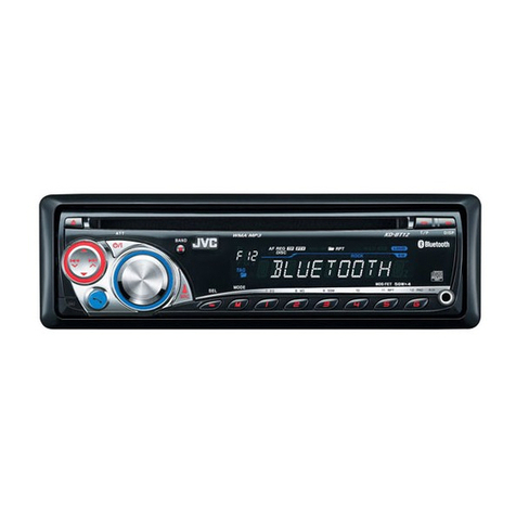
KD-R731BT
Installation/Connection Manual
Manuel d’installation/raccordement
1211DTSSANJEIN
EN, FR
© 2011 JVC KENWOOD Corporation
GET0779-010A
[E/EN/EU]
Bracket / Support *
Pocket / Poche
Flat head screws (M5 × 8 mm) /
Vis à tête plate (M5 × 8 mm)*
INSTALLATION / INSTALLATION
When installing the unit without using the sleeve / Lors de l’installation de
l’appareil scans utiliser de manchon
In-dash mounting / Montage encastré
WARNINGS / AVERTISSEMENTS
Removing the unit / Retrait de l’appareil
Release the rear section first... / Ouvrez la section arrière en premier...
Do the required electrical connections. /
Réalisez les connexions électriques.
Bend the appropriate tabs to hold the sleeve
firmly in place. / Tordez les languettes appropriées
pour maintenir le manchon en place.
Install the unit at an angle
of less than 30˚. / Installez
l’appareil avec un angle de
moins de 30˚.
* Not supplied for this unit.
* Non fourni avec cet appareil.
Part list / Liste de pièces
A
Hard case / Etui de transport (×1)
B
Control panel / Panneau de
commande (×1)
C
Sleeve / Manchon (×1)
D
Trim plate / Plaque d’assemblage (×1)
E
Power cord / Cordon d’alimentation
(×1)
F
Handles / Poignées (×2)
G
Microphone / Microphone (×1)
H
KS-UBT1: USB Bluetooth adapter /
Adaptateur USB Bluetooth (×1)
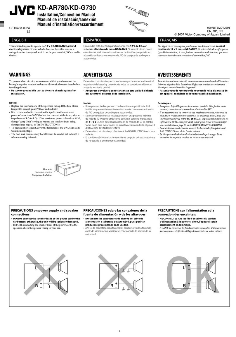
• Mounting and wiring this product requires skills and experience. For safety’s sake, leave this work to
professionals. If you experience problems during installation, consult your JVC car audio dealer.
• The unit can only be installed in a car with a 12 V DC power supply, negative ground.
• Disconnect the battery’s negative terminal and make all electrical connections before installing the unit.
• Connect speakers with a maximum power of more than 50 W (impedance of 4 Ω to 8 Ω). Otherwise,
change the <AMP GAIN> setting. (See page 21 of the INSTRUCTIONS.)
• Insulate unconnected wires with vinyl tape or other similar material. To prevent a short circuit, do not
remove the caps on the ends of the unconnected wires or the terminals.
• If the fuse blows, first make sure the wires are not touching to cause a short circuit, then replace the old
fuse with one that has the same rating.
• Install this unit in the console of your vehicle.
• Mount the unit so that the mounting angle is 30° or less.
• Be sure to ground this unit to the car’s chassis again after installation.
• After the unit is installed, check whether the brake lamps, blinkers, wipers, etc. on the car are working
properly.
• Do not touch the metal part of this unit during and shortly after the use of the unit. Metal part such as the
heat sink and enclosure become hot.
• Le montage et le câblage de ce produit nécessitent des compétences et de l’expérience. Pour des raisons de
sécurité, laissez un professionnel effectuer le travail de montage et de câblage. Si vous rencontrez des problèmes
durant l'installation, consultez votre revendeur d’autoradio JVC.
• L’appareil peut uniquement être installé dans une voiture avec une alimentation de 12 V CC, à masse négative.
• Déconnectez la borne négative de la batterie et réaliser toutes les connexions avant d’installer l’appareil.
• Connectez des enceintes avec une puissance maximum de 50 W (impédance de 4 Ω à 8 Ω). Sinon, changez le
réglage <AMP GAIN>. (Voir la page 21 du MANUEL D’INSTRUCTIONS.)
• Isolez les câbles non-connectés avec un ruban de vinyle ou d’un autre matériel similaire. Pour éviter les courts-
circuits, ne retirez pas non plus les capuchons à l’extrémité des câbles non-connectés ou des prises.
• Si un fusible saute, assurez-vous d’abord que les câbles n’ont pas causé de court-circuit puis remplacez le vieux
fusible par un nouveau de même valeur.
• Installez cet appareil dans la console de votre véhicule.
• Monter l’unité de façon à ce que l’angle de montage soit de 30˚ ou moins.
• Assurez-vous de raccorder de nouveau la mise à la masse de cet appareil au châssis de la voiture après l’installation.
• Après avoir installé l’appareil, vérifiez si les lampes de frein, les indicateurs, les clignotants, etc. de la voiture
fonctionnent correctement.
• Ne touchez pas la partie métallique de cet appareil pendant ou juste après son utilisation. Les parties métalliques,
comme le dissipateur de chaleur et le boîtier, deviennent chaudes.
PRECAUTIONS on power supply and speaker connections
• DO NOT connect the speaker leads of the power cord to the car battery; otherwise, the unit will be
seriously damaged.
• BEFORE connecting the speaker leads of the power cord to the speakers, check the speaker wiring in
your car.
PRECAUTIONS sur l’alimentation et la connexion des enceintes
• NE CONNECTEZ PAS les fils d’enceintes du cordon d’alimentation à la batterie; sinon, l’appareil serait
sérieusement endommagé.
• AVANT de connecter les fils d’enceintes du cordon d’alimentation aux enceintes, vérifiez le câblage des enceintes
de votre voiture.
ENGLISH / FRANÇAIS
• The fuse blows.
h
Are the red and black leads connected correctly?
• Power cannot be turned on.
h
Is the yellow lead connected?
• No sound from the speakers.
h
Is the speaker output lead short-circuited?
• “MISWIRING CHK WIRING THEN RESET UNIT”/ “WARNING CHK WIRING THEN RESET UNIT” appears
on the display and no operation can be done.
h
Is the speaker output lead short-circuited or touches
the chassis of the car/head unit? ; Have you reset your unit?
• Sound is distorted.
h
Is the speaker output lead grounded? ; Are the “–” terminals of L and R speakers
grounded in common?
• Noise interfere with sounds.
h
Is the rear ground terminal connected to the car’s chassis using shorter
and thicker cords?
• This unit becomes hot.
h
Is the speaker output lead grounded? ; Are the “–” terminals of L and R
speakers grounded in common?
• This unit does not work at all.
h
Have you reset your unit?
• Le fusible saute.
h
Les fils rouge et noir sont-ils racordés correctement?
• L’appareil ne peut pas être mise sous tension.
h
Le fil jaune est-elle raccordée?
• Pas de son des enceintes.
h
Le fil de sortie d’enceinte est-il court-circuité?
• “MISWIRING CHK WIRING THEN RESET UNIT”/ “WARNING CHK WIRING THEN RESET UNIT” apparaît
sur l’affichage et aucune opération ne peut être réalisée.
h
Est-ce qu’un fil de sortie d’enceinte est court-
circuité ou touche le châssis de la voiture/appareil principal? ; Avez-vous réinitialisé votre appareil?
• Le son est déformé.
h
Le fil de sortie d’enceinte est-il à la masse? ; Les bornes “–” des enceintes gauche et droit
sont-elles mises ensemble à la masse?
• Interférence avec les sons.
h
La prise arrière de mise à la terre est-elle connectée au châssis de la voiture avec
un cordon court et épais?
• Cet appareil devient chaud.
h
Le fil de sortie d’enceinte est-il à la masse? ; Les bornes “–” des enceintes
gauche et droit sont-elles mises ensemble à la masse?
• Cet appareil ne fonctionne pas du tout.
h
Avez-vous réinitialisé votre appareil?
TROUBLESHOOTING / EN CAS DE DIFFICULTES
Install_KD-R731BT[E]_010A.indd 1Install_KD-R731BT[E]_010A.indd 1 11/30/2011 4:54:11 PM11/30/2011 4:54:11 PM
