JVC KW-XC8 User manual

SERVICE MANUAL
COPYRIGHT © 2002 VICTOR COMPANY OF JAPAN, LTD.
No.49761
2002/11
KW-XC8
CD/CASSETTE RECEIVER
49761200211
KW-XC8
This model is KW-XC8_UN that is added to the preceding model,the KW-XC828_U.
Therefore ,this service manual is consisting of diffrence parts list with KW-XC828_U.
Please refer to the service manual of KW-XC828_U.(issue No.49729)

KW-XC8
2
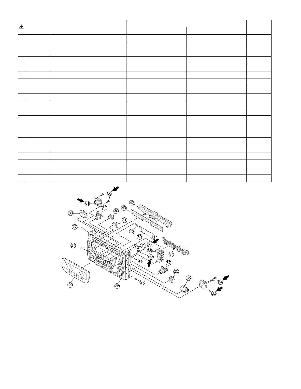
Parts list (General assembly) [P3-3 Block NO.M1MM]
Item parts name parts namber Q'ty
KW-XC828_U KW-SC8_UN
28 F.PLANEL LV10613-011B LV33945-001A 1
29 FINDER LV21159-010B LV21403-001A 1
30 PUSH BUTTON 1 LV33139-001A LV33934-001A 1
31 PUSH BUTTON 2 LV33140-001A LV33935-001A 1
32 PUSH BUTTON 3 LV33141-004A LV33936-001A 1
33 PUSH BUTTON 4 LV33142-004A LV33937-001A 1
34 PUSH BUTTON 5 LV21158-001A LV21404-001A 1
35 PUSH BUTTON 6 LV33143-001A LV33938-001A 1
36 PUSH BUTTON 7 LV33144-004A LV33939-001A 1
37 PUSH BUTTON 8 LV33145-004A LV33940-001A 1
38 PUSH BUTTON 9 LV33146-006A LV33941-001A 1
46 SPACER LV40846-030A ------------- 2
47 MAME PLATE LV33414-001A LV33875-001A 1
48 CAUTION LABEL LV42940-001A ------------- 1
61 BUTTON HOLDER L ------------- LV33942-001A 1
62 BUTTON HOLDER R ------------- LV33943-001A 1
63 CS GUIDE ------------- LV43265-001A 1
64 MINI SCREW ------------- VKZ4777-003 2
65 MINI SCREW ------------- VKZ4777-003 2
66 MINI SCREW ------------- VKZ4777-003 1

KW-XC8
3
Parts list (Packing) [P3-23 Block NO.M3MM]
Parts list (Accessories) [P3-23 Block NO.M5MM]
Item parts name parts namber Q'ty
KW-XC828_U KW-SC8_UN
P1 POLY BAG QPA0170350P ---------------- 1
P4 CARTON LV33415-001A LV33876-001A 1
Item parts name parts namber Q'ty
KW-XC828_U KW-SC8_UN
A1 INST BOOK LVT0835-001A ---------------- 1
(ENG,CHI,THA,ARA)
A2 SETTING MANUAL LVT0834-002A ---------------- 1
A3 MP3 MANUAL LVT0918-001A ---------------- 1
A4 VJC3300-001 BLIND PLATE ---------------- 1

(No.49761)
KW-XC8
MOBILE ELECTRONICS BUSINESS DIVISION
PERSONAL & MOBILE NETWORK BUSINESS UNIT. 10-1,1chome,Ohwatari-machi,Maebashi-city,371-8543,Japan
VICTOR COMPANY OF JAPAN, LIMITED
2002/11
Printed in Japan

SERVICE MANUAL
CD/CASSETTE RECEIVER
No.49729
Apr. 2002
COPYRIGHT 2002 VICTOR COMPANY OF JAPAN, LTD.
KW-XC828
KW-XC828
Area Suffix
U Ather Areas
Contents
Safety precaution
Disassembly method
Adjustment method
Flow of functional
operation unit TOC read
1-2
1-3
1-30
1-31
Maintenance of laser pickup
Replacement of laser pickup
Description of major ICs
1-33
1-33
1-36
E
X
DIRECTORY
SOUND
VOL VOL
SOURCE
RF
U
D
ATT

1-2
KW-XC828
!
CAUTION
Burrs formed during molding may be left over on some parts of the chassis. Therefore,
pay attention to such burrs in the case of preforming repair of this system.
Safety precaution
!
CAUTION
Please use enough caution not to see the beam directly or touch it in case of an
adjustment or operation check.

1-3
KW-XC828
Remove the four screws Aon both sides of the
body.
Release four joints aon both sides of the body using
a screwdriver and remove the front panel assembly
toward the front. The connector which connects the
front panel assembly with the rear section comes off.
1.
2.
Disassembly method
Removing the front panel assembly
(See Fig.1 ~ 3)
When reassembling, make sure that
connector CN501 on the front panel
assembly is securely connected to
CN701 on the main board (See Fig.3).
CAUTION:
A
A
A
A
CN701
CN501
Joint a
Joint a
Front panel assembly
Fig.1
Fig.2
Joint a
Joint a
Front panel assembly
Fig.3
Front panel assembly

1-4
KW-XC828
Prior to performing the following procedure, remove
the front panel assembly.
Remove the twelve screws B retaining the system
control board.
Remove the five screws Cretaining the switch
board.
Unsolder WR501 and WR502 of the wires
connecting the system control board with the switch
board.
1.
2.
3.
Removing the system control board /
switch board (See Fig.4 , 5) B
B
B
Switch board
Switch board
System control board
CC
B
WR502
WR502
WR501
WR501
WR502
Fig.4
Fig.5
System control board
B

1-5
KW-XC828
Prior to performing the following procedure, remove
the front panel assembly.
Remove the ten screws D, the screw Eand F
attaching the rear panel on the back of the body.
Remove the three screws Gand the two screws H
attaching the heat sink on the left side.
Remove the three screws Iattaching the CD player
section and the cassette player section on the both
sides of the body.
Disconnect the card wire from connector CN702 on
the main board in the CD player section on the back
of the body.
Remove the CD player section upward.
1.
2.
3.
4.
5.
Removing the CD player section /
cassette player section (See Fig.6 ~ 10)
When reassembling, joint the CD player
section and the cassette player section
at four joints b.
CAUTION:
D
D
E
D
G
GI
I
I
CN702
CD player section
Cassette player section
Joint b
F
H
Heat sink
Rear panel Fig.6
Fig.7
Fig.8
Fig.10Fig.9
Joint b
CD player section
Joint b Cassette player section

1-6
KW-XC828
Remove the three screws Jattaching the main
board. The connector CN601 on the main board is
disconnected from the CD mechanism control board.
1.
<CD player section>
Removing the main board (See Fig.11)
Prior to performing the following procedure, remove
the main board and MP3 board.
Remove the three screws Lattaching the CD
mechanism assembly.
1.
Removing the CD mechanism assembly
(See Fig.13)
Prior to performing the following procedure, remove
the front panel assembly, the CD player section and
the cassette player section.
When reassembling, securely connect
connector CN601 on the main board to
the connector on the CD mechanism
control board.
CAUTION:
Prior to performing the following procedure, remove
the main board.
Disconnect the wire from connector CN601on the
MP3 board.
Remove the five screws Kand the MP3 board,
releasing the joint cand d.
1.
2.
Removing the MP3 board (See Fig.12)
CN601
J
J
J
CD mechanism assembly
L
K
K
LL
Fig.11
Fig.12
Fig.13
Main board
CN601
Joint c
MP3 board
Joint d

1-7
KW-XC828
Prior to performing the following procedure, remove
the main board.
Disconnect the card wire from connector CN972 on
the main board.
Remove the four screws Nfrom the bottom cover of
the cassette player section.
1.
2.
<Cassette player section>
Removing the cassette mechanism
assembly (See Fig.14 , 15)
Disconnect the card wire from connector CN972 on
the main board.
Remove the two screws Mattaching the main
board.
1.
2.
Removing the main board (See Fig.14)
Prior to performing the following procedure,
remove the cassette mechanism assembly.
Remove the screw Oand move the connector
board in the direction of the arrow to release the
two joints e.
Disconnect the wire from connector CJ402 and
the card wire from CN403 on the connector
board respectively.
1.
2.
Removing the connector board
(See Fig.16)
Prior to performing the following procedures, remove
the front panel assembly, the CD player section and
the cassette player section. MM
CN972
Cassette mechanism assembly
Bottom cover
NN
Fig.14
Fig.15
Fig.16
Main board
Joint e
Connector board
CN403
CJ402
O

1-8
KW-XC828
Remove the two screws Aon each side of the body.
Lift the front side of the top cover and move the
cover backward to release the two joints a.
1.
2.
Removing the top cover (See Fig.1 and 2)
Remove the screw Bfixing the connector board.
Solder the short-circuit point on the connector board.
Disconnect the flexible wire from the pickup.
Move the connector board in the direction of the
arrow to release the two joints b.
Unsolder the wire on the connector board if
necessary.
1.
2.
3.
4.
Removing the connector board
(See Fig.3 to 5)
Before disconnecting the flexible wire
from the pickup, solder the short-circuit
point on the pickup. No observance of
this instruction may cause damage of
the pickup.
CAUTION:
Unsolder the short-circuit point after
reassembling.
CAUTION:
Fig.1
Fig.2
Fig.3
Fig.4Fig.5
A
A
A
B
B
Joints a
Joints a
Top cover
Top cover
Connector board
DET switch
Pickup
Pickup
Short-circuit
Joints b
Short-circuit point
(Soldering)
Flexible wire
Flexible wire
Connector board
Frame
< CD mechanism section >

1-9
KW-XC828
Extend the two tabs cof the feed sw. holder and pull
out the switch.
Unsolder the DET switch wire if necessary.
1.
2.
Removing the DET switch
(See Fig.3 and 6)
Prior to performing the following procedure, remove
the top cover and the connector board.
Remove the two suspension springs (L) and (R)
attaching the chassis unit to the frame.
1.
Removing the chassis unit
(See Fig.7 and 8)
The shape of the suspension spring (L)
and (R) are different. Handle them with
care.
CAUTION:
When reassembling, make sure that the
three shafts on the underside of the
chassis unit are inserted to the dampers
certainly.
CAUTION:
Fig.3
Fig.6
Fig.8Fig.7
B
Connector board
DET switch
DET switch
Pickup
Short-circuit
Joints b
Tab c
Feed sw. holder
Tab c
Suspension spring (L)
Suspension spring (R)
Chassis unit
Chassis unit
Frame
Frame
Shafts
Shaft
Damper
Damper
Damper

1-10
KW-XC828
Prior to performing the following procedure, remove
the top cover, the connector board and the chassis
unit.
Remove the screw Cand move the loading / feed
motor assembly in the direction of the arrow to
remove it from the chassis rivet assembly.
Disconnect the wire from the loading / feed motor
assembly if necessary.
1.
2.
Removing the loading / feed motor
assembly (See Fig.11 and 12)
Prior to performing the following procedure, remove
the top cover.
Remove the clamper arm spring.
Move the clamper assembly in the direction of the
arrow to release the two joints d.
1.
2.
Removing the clamper assembly
(See Fig.9 and 10)
When reassembling, connect the wire
from the loading / feed motor assembly
to the flame as shown in Fig.11.
CAUTION:
Fig.9
Fig.10
Fig.12Fig.11
Clamper arm
spring
Clamper arm spring
Chassis rivet
assembly
Joint d
Joint d Clamper assembly
Clamper assembly
Joint d
Joint d
Chassis rivet assembly
Loading / feed motor assembly
C

1-11
KW-XC828
Reattach the feed rack to the pickup unit using the
screw F.
Reattach the feed sw. holder to the feed rack while
setting the joint tab gto the slot of the feed rack and
setting the part fof the feed rack to the switch of the
feed sw. holder correctly.
As the feed sw. holder is temporarily attached to the
pickup unit, set to the gear of the joint gand to the
bending part of the chassis (joint h) at a time.
1.
2.
3.
Reattach the feed sw. holder using the screw E.
Reattach the shaft to the pickup unit. Reattach the
pu. shaft holder to the shaft using the screw D.
4.
5.
Reattaching the pickup unit
(See Fig.13 to 16)
Prior to performing the following procedure, remove
the top cover, the connector board and the chassis
unit.
Remove the screw Dand pull out the pu. shaft
holder from the shaft.
Remove the screw Eattaching the feed sw. holder.
Move the part eof the pickup unit upward with the
shaft and the feed sw. holder, then release the joint f
of the feed sw. holder in the direction of the arrow.
The joint gof the pickup unit and the feed rack is
released, and the feed sw. holder comes off.
Remove the shaft from the pickup unit.
Remove the screw Fattaching the feed rack to the
pickup unit.
1.
2.
3.
4.
5.
Removing the pickup unit
(See Fig.13 to 17)
Make sure that the part ion the underside
of the feed rack is certainly inserted to the
slot jof the change lock lever.
CAUTION:
Fig.13
Fig.14
Fig.15
Fig.17Fig.16
Feed sw. holder
Feed sw. holder
Feed sw. holder
E
D
D
E
F
Joint f
Joint f
Joint f
Joint g
Joint f
Joint e
Joint e
Pickup unit
Pu. shaft holder
Pu. shaft holder
Shaft
Shaft
Feed rack
Feed rack
Pickup unit
Pickup unit
Feed sw. holder
Pickup unit
Feed rack
Pickup unit
Joint h
Part i
Slot j
Joint g

1-12
KW-XC828
Prior to performing the following procedure, remove
the top cover, the connector board, the chassis unit,
and the clamper assembly.
Remove the screw H.
Move the top plate assembly in the direction of the
arrow to release the two joints p.
Unsolder the wire marked qif necessary.
1.
2.
3.
Removing the top plate assembly
(See Fig.20)
Prior to performing the following procedure, remove
the top cover, the connector board and the clamper
unit.
Turn the trigger arm in the direction of the arrow to
release the joint kand pull out upward.
1.
Removing the trigger arm
(See Fig.18 and 19)
When reassembling, insert the part land
mof the trigger arm into the part nand
oat the slot of the chassis rivet
assembly respectively and join the joint
kat a time.
CAUTION:
Fig.18
Fig.19
Fig.20
Joint k
Trigger arm
Trigger arm
Chassis rivet assembly
Part n
Part l
Part m
Part o
Top plate assembly
Joints p
q
H

1-13
KW-XC828
Reattach the select lock arm spring to the top plate
and set the shorter end of the select lock arm spring
to the hook uon the top plate.
Set the other longer end of the select lock arm spring
to the boss von the underside of the select lock arm,
and join the select lock arm to the slots (joint t). Turn
the select lock arm as shown in the figure.
Reattach the select arm (L) while setting the part rto
the first peak of the link plate gear, and join the joint
s.
1.
2.
3.
Reassembling the select arm (L) / select
lock arm (See Fig.23 to 25)
Prior to performing the following procedure, remove
the top plate assembly.
Bring up the select arm (L) to release from the link
plate (joint r) and turn in the direction of the arrow to
release the joint s.
Unsolder the wire of the select arm (L) marked qif
necessary.
Turn the select lock arm in the direction of the arrow
to release the two joints t.
The select lock arm spring comes off the select lock
arm at the same time.
1.
2.
3.
Removing the select arm (L) / select lock
arm (See Fig.21 and 22)
When reattaching the select arm (L),
check if the points wand xare correctly
fitted and if each part operates properly.
CAUTION:
Reverse the above removing procedure.
REFERENCE:
Fig.21
Fig.22
Fig.23
Fig.25Fig.24
Top plate
Top plate
Select arm (L)
Select lock arm
Select lock arm Select lock
arm spring
Select lock arm
Select lock arm
Select
lock arm
Joint r
Link plate
Link plate
Joint z
Joint z
Joint a'
Select arm (R)
Joint y Joint s q
Link plate spring
Joint b'
Joints t
Hook u
Hook u
Boss v
Select lock arm spring
Joint t
Joint t
Link plate Joint r
Point x
Select arm (L)
Select arm (R) Joint a'
Joint b'
Link plate spring
Joint r
Joint s

1-14
KW-XC828
Reattach the link plate spring.
Reattach the link plate to the link plate spring while
joining them at joint b’.
Reattach the part yof the select arm (R) to the first
peak of the link plate while joining the two joints z
with the slots. Then turn the select arm (R) as shown
in the figure. The top plate is joined to the joint a’.
1.
2.
3.
Reattaching the Select arm (R) / link
plate (See Fig.25 and 26)
Prior to performing the following procedure, remove
the top plate assembly.
Bring up the select arm (R) to release from the link
plate (joint y) and turn as shown in the figure to
release the two joints zand joint a’.
Move the link plate in the direction of the arrow to
release the joint b’. Remove the link plate spring at
the same time.
1.
2.
Removing the select arm (R) / link plate
(See Fig.21 and 22)
When reattaching the select arm (R),
check if the part c’ is correctly fitted and
if each part operates properly.
CAUTION:
Reverse the above removing procedure.
REFERENCE:
Before removing the link plate, remove
the select arm (L).
REFERENCE:
Fig.26
Fig.21
Fig.22
Top plate
Top plate
Select arm (L)
Select lock arm
Select lock arm Select lock
arm spring
Select lock arm
Joint r
Link plate
Link plate
Link plate
Joint z
Joint z
Joint a'
Select arm (R)
Part y Joint s q
Link plate spring
Joint b'
Joints t
Hook u
Fig.25
Select
lock arm
Point x
Select arm (L)
Select arm (R) Joint a'
Joint b'
Link plate spring
Part y
Joint z
Joint z Part y

1-15
KW-XC828
Prior to performing the following procedure, remove
the clamper assembly and the top plate assembly.
Push inward the loading roller assembly on the gear
side and detach it upward from the slot of the joint d’
of the lock arm rivet assembly.
Detach the loading roller assembly from the slot of
the joint e’of the lock arm rivet assembly.
The roller guide comes off the gear section of the
loading roller assembly.
Remove the roller guide and the washer from the
shaft of the loading roller assembly.
Remove the screw Iattaching the lock arm rivet
assembly.
Push the shaft at the joint f’of the lock arm rivet
assembly inward to release the lock arm rivet
assembly from the slot of the slide plate. Extend the
lock arm rivet assembly outward and release the
joint g’from the boss of the chassis rivet assembly.
The roller guide springs on both sides come off.
1.
2.
3.
Removing the loading roller assembly
(See Fig.27 to 29)
When reassembling, reattach the left
and right roller guide springs to the lock
arm rivet assembly before reattaching
the lock arm rivet assembly to the
chassis rivet assembly. Make sure to fit
the part h’of the roller guide spring (L)
inside of the roller guide (Refer to
Fig.30).
CAUTION:
Fig.27
Fig.28-1
Fig.28-2
Fig.29Fig.30
Roller guide
Roller guide spring
Roller guide spring
Roller guide spring
Roller guide
spring
Roller guide
spring
Roller guide spring
Roller guide
Washer
Loading roller assembly
Joint e'
Joint d'
Lock arm rivet assembly
Chassis rivet assembly
Boss
Slide plate
Joint f'
Part g'
Lock arm rivet assembly
I
Roller guide
Washer
Frame Roller guide spring
Loading roller
Roller shaft assembly
Joint h'

1-16
KW-XC828
Prior to performing the following procedure, remove
the top cover, the chassis unit and the top plate
assembly.
Remove the screw Jattaching the loading gear
bracket. The loading gear (6) and (7) come off the
loading gear bracket.
Pull out the loading gear (5).
1.
2.
Removing the loading gear (5), (6) and
(7) (See Fig.31 and 32)
Fig.31
Fig.32
J
J
Loading gear bracket
Loading gear (6)
Loading gear (5)
Loading gear (6)
Loading gear (5) Loading gear (7)
Loading gear (3)
This manual suits for next models
1
Table of contents
Other JVC Car Receiver manuals

JVC
JVC KD-G335 User manual

JVC
JVC KD-Lh401 User manual

JVC
JVC EXAD KD-SHX855 Guide

JVC
JVC KD-G805 User manual

JVC
JVC GET0641-001A Parts list manual

JVC
JVC KD-BT11 - Radio / CD User manual

JVC
JVC KD-G331 Guide

JVC
JVC KD-SH55R User manual

JVC
JVC KD-S580 User manual

JVC
JVC Cassette Receiver KS-FX433R User manual