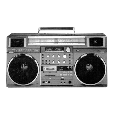
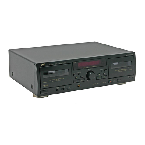
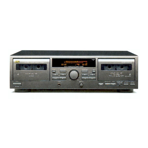
JVC CX-F5K User manual

JVC
MODEL
CX-F5K,
CX-5K
8
For specifications,dimensions and weights of these models, refer to the Instruction Book herewith
attachedtothis ServiceManual.
Contents
Location of Main Parts
. . . . . . .
.
. .
.
.
. . . . . . . . .
. .
.2
Removal of Main Parts
.
.
. .
. . .
.
. . . . . . . . .
.
. . . . .
.3
Positioning of the pointer
.
.
.
.
.
.
. . . . . .
. .
. . . . . . .
.
4
Service and check method.
. .
.
. .
.
. . . . . .
.
. .
.
. . .
5
Main Adjustments
. . . . .
.
. . . . . . . . . . .
.
.
. . . . . . . .
6
Parts Arrangement for Alignment
. . . . . . . .
. .
. . . . .
.8
Standard Schematic Diagram of CX-5K.
. . . . . . . .
.
.
.
9
Standard Schematic Diagram of CX-F5K
(Amplifire section).
.
.
. . . . . .
.
. . . .
.
. . . .
.
. . .
.
. . .
10
Standard Schematic Diagram of CX-F5K
(Tuner section)
. . . . . . . . . . .
. .
.
. . .
.
. . .
.
. . . . .
.
.
11
P. C. Board Parts (MainBoard of CX-5K)
. . .
.
. .
.
. .
12
P. C. Board Parts (Main Board of CX-F5K).
. . . . . .
.
.
13
P. C. Board Parts (Governer Board)
. . . .
. . . .
. .
.
.
.
.
14
P.
C. Board Parts List (Main Board of CX-5K)
. .
.
.
.
.
14
P. C. Board Parts List (Main Boardof CX-F5K)
.
.
. . .
15
Exploved view of Mechanism 18
Assembly and Parts List.
.
.
. . . . . . . .
..
. . . . . . .
.
.
17
Exploved view of Enclosure Assembly and Parts List
. .
18
Packing and Packing Parts List
. . . .
.
. .
.
. . . . . . .
. .
21
Accessories
. . . .
.
. .
.
. . . . . . .
.
. . . . .
.
.
.
.
Back Cover
No. 1665
Novern
ber
1985

Location
of
Main
Parts(~echanisrn
section)
Top
View
ldler Gear(R)
ldler Gear(F)
Motor
Main puly
Sub chassis
I
I
Bottom
View
Capstan Motor
1
Belt
1
Pinch Roller
I
I
Arimus Adj ~ckew
I
P. B Head
I
~ituatorBraeket
Pinch Roller(FWD)
Elrevtor
I
Reel unit
~ctuatbrMotor
I
I
Main Pulley
I
Flywheel(REV)
Flywheel(FWD)
2
(No.
1665)

Removal of Main Parts
Note:This unitcan easily be damaged by incorrect servicing
due to
its
compact size. To avoid this, classify the
mountingscrews in removal.
Lid
Ass'y
1.
Remove the slide knobof the REVERSE MODE switch.
2.
Remove three screws
@
secured from the front, two
screws
@
on both sides and three screws
@
secured
from theinside.
(Theazimuth can be adjusted in this condition.)
Note:When assembling the lid ass'y, confirm that there is
no deformation of the contacts on the PWBs in the
mechanism operation section.
BottomCover
1.
Remove the eject knob by holding it up and pushing it
out.
2.
Remove two screws
13
fixing the bottom cover from
bothsides.
3.
Remove a screw
@
fixing the middle of the name
plate.
4.
Removea screw
@.
5.
Removethe bottom cover from the reverse side.
Inner Liner
Remove four screws
@,
@
and
@.
Note:Too much pressure will break the flexible PWB; it
requires very careful handling.
(No. 1665)
3

Boardsand Mechanism
1. Remove twoscrews 11 fixing the main PWB on the lid
side and twoscrews
12
fixing the contact PWB.
2.
Remove twoscrews 13 fixing the PWB on the bottom.
tact PWB.
8
Note:The spring can be removed by removing the con-
3. To remove the chassis, remove three screws
'@
and
8.
4.
~fterthe above procedure, it can be seen that the actu-
ator motor of mechanism and the head ere soldered to
the main PWB and the capstan motor and the wire of
the
@
side of the battery are soldered to the governor
PWB.
MechanismAss'y
1. Remove the head lead and the wire of the actuator
motor from the main PWB.
2.
Remove the wire of the capstan motor and wires, etc.
connectedto the main PWB.
Positioning of the pointer
SPSJ1735N
L?
Adjustment of
Pointer Position
4
(No. 1665)

Service
and
check method
Note: When disassembled, the CX-F5/CX-5 cannot be
operated normally, so check as described below.
1.
Explodedview
(This illustration shows the mechanism ass'y set up verti-
cally. Inorder to
set
it
up vertically, removethe governor
P.C.B. from the chassis.)
2.
Check procedure
1) Disassemble as shown in Fig. 1. (The unit does not
operate inthis condition.)
2) Solder the wires at points
@
to
@
where thewires
go out. (Avoid re-solderingafter this as itwill cause a
malfunctionafter assembly.)
3)
Connect Q306 collector and GND by soldering in a
wire. (Sinceremovingthe governor P.C.B. causes auto
stop to operate, this
is
defeated by the wire.)
.
~
1) Connect wires
@,
@
and
@
andwire
@
.
2) Position the slide switch of the governor
P.C.B.
tothe
switch arm position of the mechanism ass'y.
3) Temporarily connect the PLAY/DIRECTlON button
and point
@
with awire.
*
After the above procedure, itis possible todo normal
operations.
4.
Operation modes
Terminal
Notes:
"-"
indicatesopen.
"L" indicatesthat it is grounded (point
@
).
"H"
indicates open with B+ supplied from the
mechanism control IC.
Main Board
I
Collector
Q30,k
E
PLAY/DIRECTION
STOP
Mecha Ass'y
(No.
1665) 5

Main Adjustments
CASSETTE ADJUSTMENTS
Conditions Power supply
:
DC 1.5 V
Output
:
Load impedanceof 16
Cl
at headphonesterminals
I
Tape tobe used
1
Items Adjustment procedure
1.
frequency
response check
2.
sensitivity
adjustment
Azimuth
adjustment
Tape speed
adjustment and
wow
&
flutter
check
VTT736
I
follows with respectto 1 kHz.
Test tape
VTT702 (8kHz)
Test tape
VTT712 (3kHz)
Test tape
I
(Normal) 125 Hz
:
-2 dB
f
3 dB
Play back the
test
tape in the FWD and REV
modes and adjust to the mid-point of both
peak levels.
(Apply locking compoundafter adjustment.)
Play back the test tape and adjust the tape
speed so that the counter readingis 3010 Hz
inthe FWD PLAY mode and 2955-3075 Hz
in the REV mode.
Wow
&
flutter should be within 0.5% (JIS
RMS).
The playback output level should be
as
(Metal) 8kHz:-4dBf3dB
Test tape Play back the test tape and adjust so that the
VTT724 (1kHz) output of PB GAIN TP is -25 dB
f
1dB in
the FWD PLAY mode for both L and R
i
Auto stop level
*
Playback Test tape
adjustment
output check
channels.
VTT662 The output
at
the headphoneterminalshould
be 5 mW (0.28 Vl16
Cl)
at 1
%
distortion.
The level difference between L and R chan-
nels should be within 3 dB.
Apply 2.8Vto
+2.2 V line and adjust VR303
so that TP (Q309E) is high (approx. 1.5 V)
and low when the black and white sections
of idler gear F are placed to cover the photo-
coupler. Perform the high and low checking
with the governor PWB installed in the
mechanism.
Select switch
TAPE 70 ps
I
-
Adjustment points
TAPE VR302 on the
governor PWB
6
(No. 1665)
TAPE 120ps
TAPE 70ps
TAPE 70ps
-
Increase 2 dB when
the up points are
short-circuited.
Decrease 2dB when
the down points are
open.
-

TUNER ADJUSTMENTS
(CX-F5K/G)
Conditions Power supply
:
DC 1.5 V
Volume control
:
Set to maximum. (However, set to minimumduring IF adjustments.)
Output measurement point
:
Headphone, output level of 56.6 mV/16
R
Bandselect switch
:
Set to RADIO
Tuning voltage adjustment
Connect the voltmeter to the governor PWB and adjust by fully turning VR2 (Tuning) to the L direction so that the voltage
between TP8 and TP2 (GND) is 1.5f0.1V.
AM
IF
adjustments
Band select switch
:
Set toAM.
Position of VR2
:
Near the minimum voltage (Low) position with no input signal.
Input
:
From TP3 terminal
I
Input signal
I
Adjustment points
I
Output measurementpoints
1
Adjustment procedure
I
(om
IF
synchro-( T3, T4
I
connect
TP~
(hotside) -TP2
sid side)
to
[Set
the output to maximurn and
scope (450kHz)
1
OUT the synchroscope. waveforms on right and left sym-
metrical.
AM
R
F
adjustments
Input
:
Standard loopantenna, SSG modulationoutput of 400 Hz, 30%
I
Items
I
lnputfrequency
I
Adjustment points
I
Positionof VR2
I
Adjustment procedure
I
1
2
FM
IF
and detector adjustments
3
4
5
6
Bandselect switch
:
Set to FM.
Position of VR2
:
Near the maximum voltage (HIGHfrequency) position with no input signal.
lnput
:
From TP4 terminal
520 kHz
1650kHz
I
Input signal
I
~djustmitpoints
1
Output measurementpoints
1
Adjustment procedLe
I
Perform adjustment by repeatingitems 1and 2.
1
From IFsynchro-( TI
+
T2
I
Connect IFOUT to the synchroscope.
I
Set the band select switch to FM.
(
L4
TC4
scope (450kHz)
I
OUT
Set the output to maximum.
Make the left and right partsof the
Scurve symmetrical by rotating T2.
Maximum voltage (HIGHfrequency)
Minimum voltage (LOW frequency)
Perform adjustment by repeating items 4 and 5.
Adjust so that 620kHz signal
is
received.
Adjust so that 1400kHzsignal
is
received.
620 kHz
1400kHz
(No. 1665)
7
Adjust tothe required frequency.
L15
L3

FM
RF
and
MPX
adjustments
Input
:
From rodantennaterminal (TP1)and ground (TP5) Band select switch
:
Set to FM.
FM SSG output
:
400 Hz, 30%(22.5 kHz DEV.) FM mode
:
Set toSTEREO.
Output impedance
:
75
R
unbalanced
Parts Arrangement for Alignment
Main
P.
W.
Board
Adjustment points Positionof
VR2
Items
1
2
TUNING
Adjustment procedure
Inputfrequency
L2
TC2
88
MHz
109 MHz
Governer
P.
W.
Board
3
4
5
lAPE
SPEED
Minimum voltage (LOWfrequency)
Maximum voltage (HIGHfrequency)
8
(No. 1665)
Adjust to the required frequency.
Perform adjustment by repeatingitems 1and 2.
Set the output to maximum.
Adjust to76 kHz.
Connect TP6
-
TP2 (GND)to the
counter.
Adjust so that 90 MHz signal
is
received.
90 MHz L1
VR1


I
I
aDDDDIDBDDDIHHHHH
WOWWWWOW00/00000
00+~NWOOPOOOOWWW
~~ICQOW~NV~~WOOO
1
WPN
D
riI)
G3D!aD
D
W W WIWWW
NNNN
~7mcnc.n
00ww
WNc0.J
03dVO
m
bA
cn
g
QC~A
1
ndD
-io
1
,
El--iZJ
-ilV
m-ix
mw
cn
w
-i
-4
-4
-4
wwww
D D
DD
ZZZZ
V)
cn cn
V)
HHHH
V)V)V)V)
m<-i
w
i'i
o
D
H
Z
oom
HUH
OrnV)
CI
--I
rn
0
w
w
ww
rn rn rn
cncnv,
HHH
mcncn
-4-i-I
000
www
wmw
rnmrn
V)
.V)
V)
HHH
V) V)
V)
-i-i-i
0 0 0
www
wlw www
rnlrn rn m rn
cncncncncn
HHHHH
V) V) V) V) V)
+-i-i++
00000
wwwww
e e e
VNN
j>r\NP
~
I
-
Z
Z
000
mV)V)V)V)V)V)
NVPVPDD
rmmcncnoo
rn rn rn rn
P P
r
r/ru
N
-A
7i
7i
I I
I
NrP
Nmcn
WWW WOCWNPW
DbD DZZZZZZ
<<<
< < < < <'<<
I
I
in
0
3
3
3
313
3
t)t,000t)
000
0
DDD
DWZJWWWW
73 73
73
-Ornrnmrnirnrn
DDD DV)V)V)V)/V)V)
0
0
0
0
H H
H
H~H
H
HHH
000000000000000
DDDDDDDDDDDDDDD
-0-0-07373-0-0-0-0-0-0-0-0w-0
DDDDDDDDDDDDDDD
0000000000010000
HHHHHHHHHHHIHHHH
+++++++++++I++++
0,00000000000000
wwwwwwwwwwwwwww
w wwwww
rn rnrnrnrnrn
V)
cncncncncn
H HHIH HH
w wwwww
...
000
www
~

1
\ \\\
0
wwr
W WWW
v
PNO
0.
OQW
000000~00
WWHWHHHW
+ +++
0 000
w
www
NN~NVVVDPPDDD~D
vvvo.mm0000000
II~VVI~NNNNNN~N
ixTTLCLLCCCCCIC
IIIIIIIIIII
WNW00NvC0QN0N
DDD
ZZZZZZZZZ
<<< <<<<<<<<<
0 00
03
3
313
3
3
z
3'3
Dr3mmr3mnnOO
0 0 0
w
000
HHHHHHHHH
m
+
0
70
1
I
rnmmrnrnoooomcncnuouwcncn
WWWWW++++
HUH1
H
+I-
HHHHH0000cncncn0~00Ucncn
cncncncncnwwwwE++uouH++
+++++
~00rnzrn000
ooooo
+aw
o
oww
wwwxw
0
C
rn
I
0
N N N N
cn
m m m
WOW3
VWQV
003cnP
Pcno.Q
,Qno.
Xlcnl
d+W+
l
mxm
+
I
+
m
D
D D
D
ZZZZ
cn cn cn cn
HHHH
cncnmcn
+ + + +
0 0 0 0
wwxw
NNND
cncncnz
a
DDDD
9
vvvo.
;O
WWVV
mVdN
4
NP9cn
m
0-3
I
wm*
+
z
I
wmv
+
+
+
0
rnrnw
m
v
W
N
r
w
+
--I --I
H
www0
Cd
D D D
Z
Z Z
9
cncnm
73
H
H
H
4
cncncn
m
+ + +
OoO
Iz
www
>
%W
W
b
\
\
\
\
\\\\\
ww
wmx~
ww
131313130
WW WWWW W W WWWNW
N
W CW+P
D
N
NVNOV
0
b
GDPV
OQ
1
mdvvm
I
--
0
0
010
w
-
mrn~~~~u~www~wwwwwww
~uuuomrnrnrnrnmrnrnrnrn
00DDDDZWWWOWmmWWm
DD000c-I
HHHHHHHHHH
UOHHHHW~WW~~~~~fJ3U3
DD++++rn++++++++++
000000cn0000000000
HHWWWWHWWAJWWXIWXWW
+
+
cn
0 0
+
ww
0
I
Z
ZIZ Z
rn
<
<~+
<
Z
I
W,0
11
N
N~
www~w~~~cn~orn~z~~mm
~fA~~~UI~0CUbO~NdWUU
PDDD
I
I+'NOWVNWNOV~V
0000z0000P01dbN0N
NNN~~N00000rn00D0vm
cccc~-wt-A~~v~
I
~r~z-0
1
1 1
1
T
1
119
1
1
v0n
XQn
kAVVVXINOWOWUIU
V)
OOOWWd0100b1
W
w
*WNWOOPOVN
-I
X
ZZZZ
<NV
Z
W
X
<<<<
N
3
3
3
-3
Z
H
U;H
~3
C C
wj'u
m
N
--I
li
DC,O~~ZZZ~.
II
rnnx
UUUHXWTOTZDP
nwwwwcccurnrn
-I
rnzz
mrnrnrnrnoo~orncncnuouwcncn
mmWWm++l+
HHH
H
HH
HHHHH000cncnm000ucn~
cncncncnmwwwE++uouH++
+++++
00000
wwwww
0
c
rn
I
N N
N
N~N
cn
0
cn cn cn
WOuJWDCWQdV
Oa3WOP
PUlOQ9
03Qn-a
X
I
COD
1
q+w\
+
I
axwm
w
I
X
+
m
HHHHH
cncncncnrn
+++++
00000
wwwww
NND
mmz
DDo.
vvo.
WWV
DVN
N
b
m
On
I
wm+
I
wv
+ +
rn
rn
a3
v
Ul
N
I-
w
++H
ww0
D
D
Z Z
cn cn
H
H
m
cn
+ +
0
0
ww
WVNVN WVC

-
z
?
~mmmpw
01
1
I
I
ZOO00
OOOW
+P++
ZOXDD
DZ
wlrnt)o;~-l-l
Om
0
w
r
m
r
z
rn
;O
+~",~++D+oJmq+cDcncnWa
100
P++
~~~~~,~3rn1ncrnr;owo~
rnOOErn-lDED
a
00
3\n00300000
00000
+N+ND
~--(~~~~oo~~roornrnouo~~ornmrn~~~o~
-I
w
0
a
~NIIWIIIII0N~IIIINcDI~I~NI
P
.
T*
rnm-
wlrnwlmwcno
DCD
mmw
UWU
Z Z
0D0
wl
V)
-
-<
@WWWWWWWWWWPPP+PPPPQ+WWWWWWWWWNNNNNNNNNN++++++++++
1\n00001WO
+++DP
v~~nrrr~~zrn*
rnrn
QD D
;OD
wl
H
rn
Z
0
D
V)
wl
-
-<
wlI~IwlwlNwl~I~fflIV)V)E~H~WE;OWrrW;OV)rWr~~fflSrNwlrEEZEwlV)DDwlwlwlwlwlrrW
o
o
EWrnrn*
wawn
C
-I
r
-<
D
V)
D
V)
wl
-
wl<
-
-c
O~0,~~WPWN+O~~~~WPWN+O~~~WC-WN~OoO~~@V1~WN+O~~~~WPWN+O~~~~W~PWWNW
V)~~~~-lnV)zccV)ccccc-lzQcccczQcwl<QzccV)czccccccccccccccwlcccc<~ccQ<
wnnn-c£Zvunnmnnnn~IuOnnnnuOT\73nOunn73C,unnnn~nnnnnnnnn73Knnn~~nno~
X~~PDI~~OPWDPP~PWwl+OPWPNOOWTWO+PPIO+PPWPP~PPPPPPPPTPWNWN~WWON
~Iq~qaWD~N\n+PWWW~WUNW~WP~NWW~WWW~~~~NNNW~~~~NN~~NNNPN+WOo~WWWU
+~am~~oo~m~~~o~~+~~++~~~m~~~~a~~~~~+m\nm~~ww++wmow~aa~m
00100
PWW
~~)~)~~~u~)~~)mv,0~~o,~0~~::owww~~~~~)E~.:--(0~)~~~)ww-~~-~~rr~~~0o~~~wlw~wlnnEc,
DDOOOO
W~~D~~~DDX~X~~V)~~~~~~V)OH;OOV)V)WXW~;~V)WOH~~~W<<WWDDDZDWW~~~H<~~D
~~wlnrne
nwwwlm
DTl D
ww w
H H
z
Z
00
NaW+PN0,a++aamWW+PNWm~WW\nW0,U,++0,0,m+0,~NO4~++aN
\nWOOOOWPO~oWWOOZ0W00000000000000300001~00wo
ESmE ma
ma
0100000000000000
~P++WWNN+N+UO++N
~o~roooornrn-
~rn~uv,v,v,wlrnrn~
~VIV)V)V)
DDQD
waww
HHHH
ZZZZ
0000
IWINIIIIIIIIII1III~IIII~~II~I
1
rnrnmurn-
~wDD
wl wl
V)
V)
- -
-<
-<
n
n
w
n
V V
0009
+DnQO
aaauwx-
+Onm
wl
o
DD~
w wwl
rn
V)W
z
-H
-<
V)
Ill
N+
77WT
0000
urn
0
0
P3
crn~rrr~~
-t~-t~z~v,
ZCIrn-
1w~crnrnaw
~rnm
D
cnrr
v,
I
m
rnPD
WWV) D
mwl
V)
--
V)
<-<
-
-<
0
wn
w
ME
r
<u
0
C
-3

I
CX-FSK, CX-5K CX-FSK, CX-5K
1
Exploved view
of
Enclosure Assembly and Parts
List
18
(No.
1665)
A
PARTS
NO.
VDL5104-001M
VYH2175-002
VYH5943-002
VYH2171-001
VYH5885-001
VKW3001-181
SPSK1735N
VYH3354-001
VKH3013-029
SSSK1725M
VYH5982-001
SPSK1416M
REF.
1
2
3
4
5
6
7
8
9
10
11
12
1
PARTS NAME
MECHANISM ASS'Y
HOLDER
SPRING
CHASSIS BASE
LOCK LEVER
SPRING
SCREW
C
RM
FLANGE COLLAR
SCREW
LEVER
MINI SCREW
13
SSSK1733M MINI SCREW
1
REMARKS
14
15
pp
16
17
18
19
25
26
27
28
29
36
37
38
40
44
45
46
47
48
48-
49
50
50-1
5
1
1
53
54
55
56
5
7
58
5
9
61
62
QTY
1
1
1
1
1
1
2
1
1
1
1
1
VYH5887-001
1
VYH6115-003
SPSH1425N
SPSK1725N
VJC3091-001
VJN3003-001
SPSH1714N
SSSK1420N
SSSK1414N
SSSH1428M
SPSJ1735N
SPSJ1735N
SPSK1425M
VYTT470-001
VYH3356-001
VJD4017-005
VYH6114-001
WSS1400N
VYTT469-002
FOO411-02
VYTT467-002
SPSJ
1720N
VJD2280-003
SPSK1720N
VYH2173-002
SSSK1733M
VYTT471-002
SSSJ1735N
VYH5892-001
VYH5904-001
VYH5893-002
VXP3154-001
VXP3154-002 SPRING
SCREW
SCREW
BATTERY COVER
PO
I
NTER
SCREW
SCREW
MINI SCREW
SCREW
MINI SCREW
MINI SCREW
MINI SCREW
SPACER
PROTECTOh
RIBBON
ARM
WASHER
BLIND
LUG TERMINAL
SPACER
SCREW
BATTERY CONTACT
INNER LAY
SCREW
ANTENNA HOLDER
MINI SCREW
SPACER
MINI SCREW
SPRING
SPRING
SPACER
PUSH BUTTON
PUSH BUTTON
-
1
1
2
1
1
1
2
4
1
1
2
2
CX-F5 ONLY
VMW3229-001
1
5
1
1
1
1
1
1
3
1
1
2
1
1
1
1
1
1
1
1
2
CONTACTPW BOARD
1

A
parts are safety assurance parts.
When replacing those parts, make sure touse the specified one.
Note: BK
=
Black RD
=
Red SL
=
Silver
A
Ref. No.
20
n
8
21
22
30-34
8
8
Parts No.
I
Parts Name
I
Remarks
I
Q*~
l
Slide Knob (Black)
"
(Gray)
'
(Black)
"
(Gray)
Cassette LidAss'y
-
BK/RD DOLBY
SL DOLBY
BKIRD TAPEITUNER
SL TAPEITUNER
BKIRD BAND
SL BAND
CX-F5K (BK)
"
(RD)
"
(SL)
CX-F5G (BK)
"
(RD)
"
(SL)
CX-5K (BK)
"
(RD)
'
(SL)
CX-5G(BK)
"
(RD)
Cassette Lid
1
"
(RD) 111
CX-5K (BK)
'
(SL)
CassetteSpring
Tap Plate
Sheet
Cassette Lens CX-F5K
CX-F5G
CX-5K
BKIRD REVERSE MODE
SL REVERSE MODE
Slide Knob
,,
BottomCover
Knob
CX-F5KIG (BK)
"
(RD)
'
(SL)
CX-5K (BK)
"
(RD)
"
(SL)
BK/RD EJECT
SL EJECT
CX-F5K (BK)
"
(RD)
Name Plate
1
1
1
1
1
1
1
1
1
1
"
(RD)
"
(SL)
CX-5K (BK)
"
lRDl
. .
"
(SL)
CX-F5G(BK)
(No.
1665) 19
1
1

This manual suits for next models
1
Table of contents
Other JVC Cassette Player manuals