manuals.online logo
Brands
  1. Home
  2. •
  3. Brands
  4. •
  5. JVC
  6. •
  7. Cassette Player
  8. •
  9. JVC TD-V711 User manual

JVC TD-V711 User manual

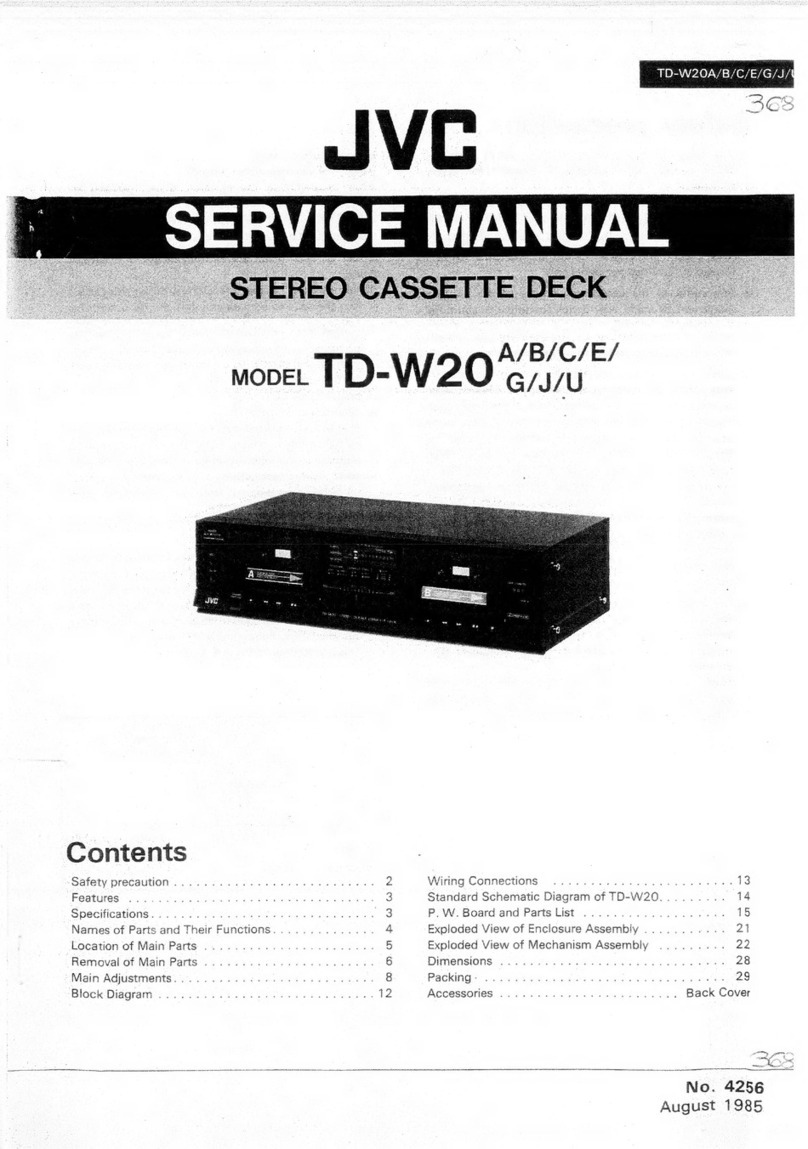
TD-V711
A/B/C/E/G/J/
_
SERVICE
MANUAL
Contents
Page
Page
[1]
Safety
Precautions
....0..0.ccccccccceeseseteerreee
2
[10]
Location
of
P.C.
Board
Parts
and
Parts
List
Specifications
........c0.ccccccceeeeee
ap
edi
aks
ateeas
3
Main:
Bat
ect
22
ccc
ace
steric
bacesecamselelaesteiateans
16
[3]
Location
of
Main
Parts
.......
iezivdead
¢
visas
oeseh
Cente
vase
4
Power
Supply/Mechanism
Control
...............5..
20
[4]
Location
of
Control
.........
saaggetagas
eee
ES
[14]
Exploded
View
of
Mechanism
Assembly
Parts
Removal
of
Main
Parts
...............
wiedcghs
pee
wu
and:
Parts:
Listisi
So.
sfeccuectsycudidda
ee
Sui
Sh
oe
ts
22
[6]
ACJUStMENt
20...
..ccc
ccc
cccececcecncccsencaucecnccscnreusecs
ew
[12]
Exploded
View
of
Enclosure
Assembly
Parts
[7]
Block
Diagram
......ccccccccccccccssecesseseesecesevssecsvese
12
and
Parts
List
.............
cece
Ledisaantet
totes:
24
[8]
Wiring
oo...
cece
‘ggasasanee
ges
aeChectonctsssa
13
[13}
Packing”
s..c.icscccssssscsssecssssesecvscsserensevseveceereeteess
28
[9]
Standard
Schematic
Diagram
.............0.....
wegen
4
[14]
ACCOSSONES
is.
sonic
Ai
Seis
sasseatieeaas
certian
ooadadasee
ed
No.
4294
March
1988
TD-V711
A/B/C/E/G/J/U
[1]
Safety
Precautions
1.
The
design
of
this
product
contains
special
hardware
and
may
circuits
and
components
specially
for
safety
pur-
poses.
For
continued
protection,
no
changes
should
be
made
to
the
original
design
unless
authorized
in
writing
by
the
manufacturer.
Replacement
parts
must
be
identical
to
those
used
in
the
original
circuits.
Service
should
be
performed
by
qualified
personnel
only.
2.
Alterations
of
the
design
or
circuitry
of
the
product
should
not
be
made.
Any
design
alterations
of
the
product
should
not
be
made.
Any
design
alterations
or
additions
will
void
the
manufacturer’s
warranty
and
will
further
relieve
the
manufacturer
or
responsibility
for
personal
injury
or
property
damage
resulting
therefrom.
3.
Many
electrical
and
mechanical
parts
in
the
product
have
special
safety-related
characteristics.
These
characteristics
are
often
not
evident
from
visual
inspection
nor
can
the
protection
afforded
by
them
necessarily
be
obtained
by
using
replacement
components
rated
for
higher
voltage,
wattage,
etc.
Replacement
parts
which
have
these
special
safety
characteristics
are
identified
in
the
Parts
List
of
Service
Manual.
Electrical
components
having
such
features
are
identified
by
(A\)
on
the
schematic
diagram
and
Parts
List
in
Service
Manual.
The
use
of
a
substitute
replacement
which
does
not
have
the
same
safety
characteristics
as
the
recommended
replace-
ment
part
shown
in
the
Parts
List
in
Service
Manual
may
create
shock,
fire,
or
other
hazards.
4.
The
leads
in
the
products
are
routed
and
dressed
with
ties,
clamps,
tubings,
barriers
and
the
like
to
be
separated
from
live
parts,
high
temperature
parts,
moving
parts
and/or
sharp
edges
for
the
prevention
of
electric
shock
and
fire
hazard.
When
service
is
required,
the
original
lead
routing
and
dress
should
be
observed,
and
it
should
be
confirmed
that
they
have
been
returned
to
normal,
after
re-assembling.
5.
Leakage
current
check
(Electrical
shock
hazard
testing)
After
re-assembling
the
product,
always
perform
an
isolation
check
on
the
exposed
metal
parts
of
the
product
(antenna
terminals,
knobs,
metal
cabinet,
screw
heads,
headphone
jack,
control
shafts,
etc.)
to
be
sure
the
pro-
duct
is
safe
to
operate
without
danger
of
electrical
shock.
Do
not
use
a
line
isolation
transformer
during
this
check.
©
Plug
the
AC
line
cord
directly
into
the
AC
outlet.
Using
a
‘‘Leakage
Current
Tester’’,
measure
the
leakage
current
from
each
exposed
metal
part
of
the
cabinet,
particularly
any
exposed
metal
part
having
a
return
path
to
the
chassis,
to
a
known
good
earth
ground.
Any
leakage
current
must
not
exceed
0.5
mA
AC
(r.m.s.).
e
Alternate
check
method
Plug
the
AC
line
cord
directly
into
the
AC
outlet.
Use
an
AC
voltmeter
having
1,000
ohms
per
volt
or
more
sensitivity
in
the
following
manner.
Connect
a
1,500
©
10
W
resistor
paralleled
by
a
0.15
»F
AC-type
capacitor
between
an
exposed
metal
part
and
a
known
good
earth
ground.
5
f
AC
VOLTMETER
Measure
the
AC
voltage
across
the
resistor
with
the
AC
Peary
(Having
1000
ohms/volt
voltmeter.
or
more
sensitivity.)
Move
the
resistor
connection
to
each
exposed
metal
part,
particularly
any
exposed
metal
part
having
a
return
path
to
the
chassis,
and
measure
the
AC
voltage
across
the
resistor.
Now,
reverse
the
plug
in
the
AC
outlet
and
repeat
each
measurement.
Any
voltage
measured
must
not
exceed
0.75
V
AC
(r.m.s.).
This
corresponds
to
0.5
mA
AC
(r.m.s.).
0.15
wF
AC
TYPE
Place
this
probe
c
on
each
exposed
1500
2
10
W
metal
part.
Good
earth
ground
Warning
.
This
equipment
has
been
designed
and
manufactured
to
meet
international
safety
standards.
.
It
is
the
legal
responsibility
of
the
repairer
to
ensure
that
these
safety
standards
are
mainteined.
.
Repairs
must
be
made
in
accordance
with
the
relevant
safety
standards.
.
It
is
essential
that
safety
critical
components
are
replaced
by
approved
parts.
.
If
mains
voltage
selector
is
provided,
check
setting
for
local
voltage.
ahWN
=
2
(No.
4294)
2)
Specifications
Type
Track
system
Tape
speed
Frequency
response
S/N
ratio
Improvement
of
MOL
Wow
and
flutter
Channel
separation
Crosstalk
Harmonic
distortion
Heads
Motors
:
Stereo
cassette
deck
:
4-track,
2-channel
:
1-7/8
inch/sec
(4.8
cm/sec)
:
(—
20 dB
recording)
Metal
tape;
10—22,000
Hz
15—20,000
Hz
(+3
dB)
Chrome
tape;
10—20,000
Hz
15—
18,000
Hz
(+3
dB)
Normal
tape;
10—20,000
Hz
15—18,000
Hz
(+3
dB)
:
59 dB
(S=1
kHz,
K3=3%
N=A-weighted,
Metal
tape)
The
S/N
is
improved
by
about
15
dB
at
500
Hz
and
by
max.
20
dB
at
1
kHz
~
10
kHz
with
Dolby
C
NR
on
and
improved
by
5
dB
at
1
kHz
and
by
10 dB
at
above
5
kHz
with
Dolby
B
NR
on.
:
4
dB
at
10
kHz
with
Dolby
C
NR
on.
:
0.022%
(WRMS)
:
40
dB
(1
kHz)
:
65
dB
(1
kHz)
:K3;
0.5%
THD;
1.0%
(metal
tape,
1
kHz
O
VU)
:
Erase
(2-Gap
Ferrite)
x
1,
Record
(Sen-Alloy)
x
1,
Playback
(Amorphous
Ferrite)
x
1
:
Pulse
servo
direct
drive
motor
for
capstan
x
1
DC
motor
for
reel
x
1
DC
motor
for
mechanism
drive
x
1
Fast
forward/Rewind
time
Imput
terminals
CD
DIRECT
(x
1
circuit)
DIRECT
(x
1
circuit)
LINE
IN
(x
1
circuit)
Output
terminals
LINE
OUT
(x
1
circuit)
PHONES
x
1
Other
terminals
Power
requirement
TD-V711A/B/E/G
TD-V711C/J
Power
consumpiton
Dimensions
(W
x
H
x
D)
Weight
Accessories
TD-V711
A/B/C/E/G/J/U
:
Approx.
95
sec.
with
C-60
cassette
:
Min.
input
level;
80
mV
Input
impedance;
50
kQ
:
Min.
input
level;
80
mV
Input
impedance;
50
kQ
:
Min.
input
level;
80
mV
Input
impedance;
50
kQ
:
Output
level;
300
mV
Output
impedance;
600
2
:
Output
level;
O~
1
mW/8
Q
Matching
impedance
82
—
1k2
:
COMPU
LINK-1/SYNCHRO
x
2
:
AC240/220/120
V,
50/60
Hz
:
AC
120
V,
60
Hz
:18W
>475
x
132
x
336mm
(18-3/4""
x
5-1/4"
x
13-1/4’’)
:
8.3
kg
(18.4
Ibs)
:
Pin
plug
cord
.............:.c08
2
Remote
cable
...............06
1
Design
and
specifications
are
subject
to
change
without
notice.
(No.
4294)
3
TD-V711
A/B/C/E/G/J/U
4
3)
Location
of
Main
Parts
Main
Board
Ass’y
Power
Switch
Power
Supply/
Power
Cord
Mechanism
Control
Board
Ass’y
input
Select
Switch
Main
Board
Ass’‘y
Power
Transformer
=
A
ae
I
>
i, ss
mn.
Volume
(Input)
q
Power
Switch—e
/
Remote
Bar
“EE
Leaf
Switch
Board
Ass’y
BIAS/BALANCE
Mechanism
Ass’‘y
Volume
Board
Ass’y
'
H.
Phones
Board
Ass’y
H.
Phones
Board
Ass‘y
Power
Supply/
Mechanism
Control
Board
Assy
Cam
Motor
Reel
Motor
Cam
Switch
Board
Cam
Motor
Ass’y
Reel
Motor
Ass’y
PB
Head
REC
Head
Pinch
Roller
E.
Head
DD
Motor
Ass’y
Pinch
roller
Fig.
3-1
(No.
4294)
4)
Location
of
Controls
TO-V711
STEREO
CASSETTIIDECK
@
TIMER
switch
When
an
optional
timer
is
used,
recording
and
playback
can
be
performed
at
any
desired
time.
@
POWER
switch
©
Cassette
holder
@
MULTI
MODE
display
(See
Fig.
4-2)
Tape
remaining
time
display
MEMORY
indicator
PEAK
LEVEL
METER
Recording
guide
indicator
Digital
peak
indicator
Tape
indicator
Digital
counter
Tape
length
indicator
Mechansim
mode
indicator
HX
PRO
indicator
NR
DEFEAT
indicator
MPX
Filter
indicator
DOLBY
NR
mode
indicator
Monitor
indicator
@
INPUT
LEVEL
control
Adjust
the
recording
level
with
this
control.
@
EJECT
button
Press
to
open
the
cassette
holder.
@
PHONES
jack
connect
headphones
(with
an
impedance
of
8
ohms
to
1
kohm).
@
PHONES
LEVEL
control
@
DOLBY
NR
switches
Set
to
ON
for
recording
using
the
Dolby
NR
SYSTEM
or
for
playback
using
the
Dolby
NR
system.
Set
to
OFF/DEFEAT
when
the
Dolby
NR
system
is
not
used.
@
Dolby
HX
PRO
switch
POWOQVOMWOOOONWO)
Fig.
4-1
@
MPxX
FILTER
siwtch
The
MPX
filter
functions
when
the
tape
is
recorded
using
the
Dolby
NR
system.
Normally,
set
this
switch
to
OFF.
When
an
FM
stereo
broadcast
is
to
be
recorded
using
Dolby
NR,
set
this
to
ON
to
prevent
the
Dolby
NR
circuit
from
malfunctioning
(otherwise
the
sound
quali-
ty
could
deteriorate).
@
INPUT
SELECT
switches
and
indicators
Press
these
to
set
to
the
inpujt
you
want
to
record.
The
corresponding
indicator
will
ight:
CD
DIRECT:
When
recording
directly
from
a
CD
player.
DIRECT:
When
recording
directly
from
other
equipment.
LINE:
When
recording
from
a
stereo
amplifier.
@®
MONITOR
button
When
recording,
set
to
SOURCE
to
monitor
the
sound
just
before
it
is
recorded.
Set
to
TAPE
to
monitor
the
sound
recorded
on
the
tape.
@®
BIAS
adjust
control
Adjust
recording
bias
according
to
the
characteristics
of
the
tape
used
for
recording.
@®
BALANCE
control
Adjusts
the
balance
between
the
signals
input
via
the
left
and
right
LINE
IN
jacks.
@
RESET
button
Press
to
reset
the
tape
counter
to
‘‘O0000’’.
@
DISPLAY
button
Select
the
mode
of
the
digital
counter.
The
tape
counter
will
be
indicated
when
the
power
is
first
switched
on.
Press
this
button
to
select
the
tape
remaining
time
display.
dis
-—30
20]
15
12
10
TD-V711
A/B/C/E/G/J/A
LEFY
Sie
It
RIGH}
C300
C
@®
TAPE
LENGTH
button
use
this
button
when
you
want
to
check
the
remaining
tape
time.
The
remaining
time
must
be
displayed
in
the
digital
counter
before
setting
the
tape
length
(e.g.,
C-60).
@®
MEMORY
button
Use
this
button
to
specify
the
position
at
which
you
want
the
tape
to
stop
in
rewind,
etc.
@)
CALL
button
(Digital
peak)
Press
to
call
up
the
stored
peakm
level
or
reset
the
memory.
@
Cassette
operation
buttons
<<
(Rewind):
Press
to
rewind
the
tape.
PLAY:
Press
to
start
recording/playback.
Press
this
but-
ton
with
either
the
<<
or
®®
button
for
music
scanning.
bP
(fast
forward):
Press
to
fast
forward
the
tape.
@
(stop):
Press
to
stop
the
tape.
©
REC/REC
MUTE:
Press
the
PLAY
button
while
pressing
this
button
to
start
recording,
and
press
to
leave
an
ap-
propriate
non-recorded
section.
Hi
(pause):
Press
to
stop
the
tape
temporarily.
Press
the
PLAY
button
to
release
the
pause
mode.
Press
this
together
with
O
REC/REC
MUTE
button
before
starting
recording
to
enter
the
record-pause
mode.
Fig.
4-2
(No.
4294)
5
TD-V711
A/B/C/E/G/J/U
[5]
Removal
of
Main
Parts
Cabinet
Section
@
Top
Cover
1)
Remove
four
screws
on
both
sides.
2)
Remove
two
screws
fixing
the
back.
@
Bottom
Cover
1)
Remove
six
screws
@)
and
a).
[Main/power
source
base
parts
can
be
replaced
in
this
condition]
@
Front
Plate
1}
Remove
INPUT
LEVEL
voiume
knob
and
BIAS/BALANCE
knob.
2)
Remove
five
screws
(2)
fixing
the
front
panel.
@
Front
Panel
Ass‘y
1)
Remove
power
switch
knob.
2)
Remove
switch
side
of
input
switch
remote
bar
and
remove
knob.
3)
Pull
input
volume
remote
bar
inside
and
remove
from
front
panel.
4)
Remove
two
screws
(3)
fixing
the
center
chassis
from
the
front.
5)
Remove
four
screws
(4)
on
both
sides.
6)
Remove
wires
if
necessary.
@
Removal
from
Front
Panel
Mechanism
Ass‘y
1)
Remove
two
screws
fixing
mechansim
ass’y
top.
2)
Remove
LED
lead
soldering
on
leaf
switch
base.
3)
Remove
two
screws
6)
fixing
mechanism
ass’y
bottom.
4)
Open
cassette
door
and
remove.
Timer
Switch
Remove
four
pawls
(A)
fixisng
the
switch
base.
Headphone
jack
Base
1)
Pull
out
output
volume
knob.
2)
Remove
nut
fixing
the
jack.
3)
Remove
volume
bracket,
push
up
volume
shaft
and
remove
from
groove.
Volume
Base
1)
Remove
two
pawls
fixing
the
BIAS
adjustment
volume/BALANCE
volume
base.
Display,
DOLBY
B/C NR,
HX,
MPX
Switch
Base
1)
Remove
two
scrws.
@)
fixing
the
switch.
2)
Remove
six
pawls
©)
fixing
the
base.
Inside
view
Fig.
5-4
Switch
Base
Ass’y
Remove
pawl
©)
,
then
remove
five
pawls
©
pawls
from
(©)
side
in
order.
Push
base
from
front
panel
hole
for
easier
removal.
(No.
4294)
6
Mechansim
Section
@
Head
parts
1)
To
remove
head
block,
remove
three
screws
@)
@)
3)
.
2)
To
remove
erasing
head,
remove
one
screw
3)
To
remove
playback
head,
remove
three
special
nuts
(5)
;
then
remove
playback
head
base
and
remove
two
screws
Caution:
A
spring
will
come
off
when
removing
playback
head.
4)
To
remove
record/playback
head.
(1)
Remove
playback
head.
(2)
Remove
three
screws
M®Ee
fixing
record/playback
head.
Caution:
Springs
@@)
are
the
same
and
@)
is
different.
(Springs
Q)
and
6)
are
the
same)
@
DD
Motor
Ass’y
1)
Remove
two
screws
;
2)
Remove
two
screws
from
both
sides
of
the
chassis.
3)
Slide
idler
to
right
and
lift
chassis
to
remove.
@
Cam
Motor
Remove
two
screws
a2
a3
‘
@
Reel
Motor
Remove
two
screws
(5)
:
@
Cam
Switch
1)
Remove
one
screw
:
2)
Slide
brake
and
pull
out.
(Cautions
for
assembling)
(1)
Align
car
gear
and
cam
switch
holes.
(2)
Head
base
arm
stud
must
match
cam
switch
gear
groove.
@
Pinch
Roller
1)
Remove
left
hexagon
nut
a?
,
2)
Remove
arm
hooked
on
chassis
on
right.
(Only
push
arm
as
required
to
remove)
®
is
playback
head
in-
Stalling
position
adjusting
.
screw.
(to
move
playback
Fig.
5-5
head back
and
forth)
Brake
(Slide
position)
Push
arm
to
remove
(Only
push
as
required
to
remove)
Fig.
5-8
TD-V711
A/B/C/E/G/J/U
16]
Main
Adjustment
1.
Measuring
instruments
required
for
adjustment
(1)
Audio
frequency
oscilloator
(5)
Recording
standard
tape
(range:
50~20
kHz
and
output
OdB
with
6000
TS-9(UDI),
TS-6(SA),
TS-7(ME)
or
the
like.
impedance)
(use
standard
tape
specified
by
Victor)
(2)
Attenuator
(impedance
600
)
(6)
Resistors
600
Q
(attenuator
matching)
(3)
Electronic
voltmeter
(7)
Distortion
gauge
(band
pass
filter)
(4)
Standard
tape
(8)
Torque
gauge
(cassette)
CTG-N
mechanical
adjusting.
VTT712
(Tape
speed,
wow
and
flutter
check)
(9)
Wow
and
flutter
gauge
VTT724
(reference
level)
(10)
Frequency
counter
VTT739
(for
playback
frequency
characteristics)
(11)
M300
gauge
VMT6447
(music
scanning)
TMT6448
(music
scanning)
TMT702
(14
kHz)
2.
Mechanical
Adjustment
When
replacing
head,
check
the
height,
direction
and
tilt
(rough
adjustment)
of
each head
as
follows.
Tape
travel
adjustment
Use
tool
M300.
Be
careful
not
to
damage
head.
Tape
guide
adjustment
Tilt
adjustment
Reflector
position
(guide
post)
Reflector
position
(guide
post)
Guage
moving
direction
Le
Fig.
6-1
Fig.
6-2
(No.
4294)
7
TD-V711
A/B/C/E/G/J/U
\
Fly
wheel
and
thrust
check
Check
by
feeling
Back
tension
rubber
position
check
At
PLAY,
back
tension
rubber
should
touch
supply
wheel
to
stop
wheel.
At
MS/Stop,
back
tension
rubber
should
not
touch
supply
wheel.
Supply
disk
Back
tension
rubber
3
|
Pinch
roller
fastening
Right
pinch
roller
should
fasten
to
capstan
shaft
order
check
before
left
pinch
roller.
4
|
Pinch
roller
guide
Use
M300
gauge
and
adjust
@
so
that
3.8
mm
height
adjustment
gauge
can
pass.
5
|
Playback
head
height
1)
Use
M300
gauge
and
adjust
playback
head
Pinch
roller
and
tilt
adjustment
tape
guide
with
screw
so
that
3.8
mm
guide
height
gauge
can
pass.
Head
guide
adjustment
2)
Adjust
©
screw
so
that
playback
head
is
not
height
j
db
tilted
and
that
there
is
no
gap
between
the
~~
i
gauge
and
head.
3)
Gaugbe
will
touch
gap
face,
adjust
carefully.
Hold
a
flash
light
from
the
opposite
side
and
check
for
light
leakage.
4)
Re-check
guide
height.
If
gauge
touches,
re-adjsut
upper
1),
2).
Playback
head
tilt
adjustment
Playback
TMT7008
(14
khz)
and
adjust
screw
(0)
to
maximum
output
position
with
no
phase
difference.
Playback
azimuth
adjustment
Tape
travel
check
Recording
head
height,
tilt.
Azimuth
adjustment
Use
C-90
padded
tape
and
check
that
tape
head
is
not
curled
at
beginning
of
wind.
Use
mirror
tape
to
check
tape
travel.
1)
Record
and
playback
10
kHz
and
adjust
screw
to
maximum
output
position
with
no
phase
difference.
(azimuth
adjustment)
2)
Record
and
playback
10
kHz
and
adjust
screw
to
maximum
output
position
with
no
phase
difference.
(height
adjustment)
3)
use
M300
gauge
and
adjust
recording
head
tilt
with
screw
@)
following
the
procedure
for
adjusting
playback
head
tilt.
4)
Record
and
playback
10
kHz
and
re-adjust
Recording
head
azimuth
adjusting
screw
(E)
to
maximum
out-
nitadjustnent
put
position.
Match
L/R
phases.
8
(No.
4294)
TD-V711
A/B/C/E/G/J/U
Head
position
Use
M300
gauge
and
adjust
so
that
playback
head
is
in
front
of
recording
head.
Other
standards
are
as
follows.
The
measurements
are
as
against
guide
post
(H).
a=3.1~4.0
Playback
{¢7
3149
Guide
Post
MS
a=4.4~5.1mm
b=0.05~0.35
d=0.2~0.3
mm
9=0°
E
Head
R
Head}ip
B
Head
d
Bend
and
adjust
head
base
so
that
a
is
within
4.4~5.1
mm
at
MS.
al
Adjusting
part
-|
=
Head
position
adjustment
Adjust
screw
®)
so
that
playback
head
is
“‘b’’
measurement
in
front
of
recording
head.
[re-adjust
playback,
recording
azimuth
after
adjusting
@).1
Excessive
Insufficient
Bend
in
#
direction
("]
Bend
in
$
direction
Ht
After
this
adjustment,
check
Item
.
Controls
clearance
between
head
base
and
door
safety
when
door
safety
is
pulled
in
the
direction
of
the
arrow
at
STOP.
Checkling
door
safety
Head
base
Door
safety
lever
3.
Electric
Circuit
Adjustment
Location
Main
Amplifier
Base
(parts
side)
Playuback
F
special
adjustment
O
VRI01
Playback
level
[vrioz
adjustment
'
'Record/Playback
bias
Playback
F
’
frequency
Sdjustment
special
adjustment
Dyvrz02
Playback
level
(yvrzo1
VR903
adjustment
adjustment
Note:
The
record
a
1
kHz,
—
20
dB
signal
is
reference
VR401
level
(—
8
dBs)
level,
so
oO
Rech
|
Record/Playback
—
20
dB
is
fow
level.
Ctch
sensitivity
adjustment
i
Ref.
Record/
level
20
dB
Papecial
H
t
—
20
dB
wo
a
(oom
&
O
z
o
6
F
'
i)
{901
C35!
Meter
adjustment
AMP
P.C.
Board
Fig.
6-3
(No.
4294)
9
TD-V711
A/B/C/E/G/J/U
|
4.
Electrical
Circuit
Adjustment
Conduct
following
adjustments
after
adjusting
tape
travel
and
head
angle.
¢
Adjust
in
the
following
order.
¢
*
marks
must
be
adjusted
when
replacing
head.
Notice:
0
dBs
=
0.775V
Adjustment
and
checking
methods
;
Dolby
fee
=
eee
|
Frequency
level
Output
value
and
deviation
recording
sored
(=Cal.
Level)
;
Adjusting
Standard
Playback
level
|
1)
Playback
VTT724
(1
kHz)
and
adjust
|VR102,
Adjust
playback
level
when
VR102,
202
so
that
LINE
OUT
out-
202
replacing
head.
put
is
—
8
dBs.
(L—R
channel
output
Electronic
voltmeter
impedance
difference
should
be
within
0.5
dBs)
should
be
over
100
kQ.
2)
Check
headphone
output
(headphone
10
kHz
VR
...
maximum)
—
15
dBs+3
dB,
L—R
difference
VR101,
201
0.5+0.5
dB
L901
95
kHz
+1
kHz
within
2
dB.
Playback
test
tape
VTT739
(1
kHz,
L304,
404
Playback
equalizer
With
1
kHz
as
reference
NR
:
OFF
63
Hz
:
+2
dB+3
dB
(Check)
10
kHz)
and
adjust
VR101,
201
so
that
1
kHz,
10
kHz
output
is
at
standard
value.
TAPE
:
METAL
(fix
needle
to
gaugbe
lead
end
and
plug
to
connector
socket)
Connect
1
MQ
to
F.
counter
and
adjust
L901
so
that
CN
3 5
PIN
output
is
95
kHz.
At
METAL
poisiton
recording
mode,
ad-
just
L304,
L404
so
that
R354
and
R454
end
voltages
are
minimum.
Record
1
kHz
at
ref
—
20
dBs
input
and
then
record
50
Hz,
12.5
kHz.
Playback
and
adjust
302,
VR402
so
that
a
deviation
of
50
Hz,
12.5
kHz
against
1
kHz
is
at
standard
value.
(Basically,
adjust
so
that
1
kHz
and
12.5
kHz
out-
put
is
at
standard
value)
Bias
frequency
adjustment
HX
PRO
coil
adjustment
DC
voltmeter
Record/
Playback
frequency
characteristics
VR302,
402)With
1
kHz
bias
as
(VR904)
reference,
should
be
at/at
12.5
kHz
the
center.
|0.5+0.5
dB
(front
volume)
Ref
~—
20
dB:
—
20
GB
lowered
from
reference
input
value
=
—
28
dB
Adjust
normal,
left,
right
channels.
¢Bias
value
of
chrome
and
metal
tape
against
normal
tape
is
set
by
voltage
shift.
elf
bias
electric
current
is
not
adjusted
correctly
the
recor-
ding
characteristic
will
be
as
the
left
diagram.
High
frequency
rise
High
frequency
lowering
Response
(dB)
Excessive
bias
Insufficient
bias
electric
current
electric
current
-~~
Correct
value
of
bias
electric
current
Freqeuncy
t2.5kHz
10
(No.
4294)
10
TD-V711
A/BIC/E/G/J/U
11
Item
Adjustment
method
Adjusting
Standard
Remarks
point
value
Recording
Input
LINE
IN
terminal
so
that
source
|
VR301,
Normal
Left
and
right
level
difference
|
level
1)
motor
output
is
—
8
dBs.
401
—8
dBs
should
be
within
1
dB
for
both
2)
Ajust
recording
signal
electric
current
+0.5
dB
|normal
and
metal.
Adjust
with
at
VR301,
401
so
that
output
is
Chrome
normal
tape.
Check
that
level
—
8
dBs
when
recorded/played
back.
Metal
difference
of
chrome
and
metal
-—8
dBs
is
within
1.5
dB
and
left
and
+1
dB
right
level
difference
is
within
1.0
dB.
Level
indicator
|
1)
Apply
1
kHz
signal
so
that
line
out-
|
VR903
Input
adjustment
put
level
becomes
-—38dB
at
—Lights
at
and
check
monitor
(source).
—
38
dB
Adjust
VR903
so
that
FL
level
in-
Lights
out
dicator
—
30
dB
lights.
at
—40
dB
Lights
should
go
out
at
—
40
cB.
2)
Check
that
O
dB
indicator
lights
at
signal
level
of
—8dB
+0.3,
—0.7
dB.
Record/
1)
Record
1
kHz
signal
so
that
level
Normal
Check
after
adjusting
bias
elec-
Playback
gauge
indicator
is
+6
dB
and
LINE
tape
under
|
tric
current
and
recording
level.
distortion
OUT
output
is
—
2
dBs.
3.0%
check
2)
Playback
and
measure
output
with
Chrome
distortion
gauge
and
check
that
it
is
tape
under
at
standard
value.
4.0%
Metal
tape
under
3.0%
Record/
1)Record
at
1
kHz,
O
dB
input.
Normal
Playback
S/N
Stop
input
during
recording
and
record
Over
45
dB
check
with
no
signal.
Chrome
2)
Playback
and
measure
difference
of
Over
45
dB
O
dB
recording
output
and
no
signal
Metal
recording
output
with
electronic
Over
45
dB
voltmeter.
Check
that
difference
is
at
standard
value.
Erasing
check
|1)
Apply
1
kHz
signal
from
LINE
IN
and
.
Over
65
dB
/Connect
B.P.F.
(band
pass
adjust
recording
volume
to
get
—8
dBs.
2)
Raise
signal
level
20
dB
and
record.
3)
Rewind
tape
and
erase
a
part
of
the
recording.
4)
Measure
output
ratio
of
recorded
part
to
erased
part
with
electronic
voltmeter.
filter)
between
electronic
voltmeter
and
deck
to
measure.
Check
with
metal
tape.
1
kHz
0
Vu
+20
dB
Deck,
recording,
input
Band
pass
filter
B.P.F.
erasing
Electronic
voltmeter
(No.
4294)
11
(v6ZP
ON)
ZL
VR102
§*
PB
DOLBY
PB
LEVEL
ADJ
B/C
NR
PB
NR
SWITCH
G)
19)
nape
MS
DETECTOR
ales
ae
|
%
(12)
4
PB
LINE
AMP
(0-0
oe
L
)
Oat
|
(5)
é
(+
S&S
<
|
PB
EQ
ADJ
(5)
7)
rt
O
1)
AUTO
MONITOR
REC
MUTE
ain
TO
MECHACON
@)—{1G915}-40.
902]
pit
INPUT
REC
LINE
AMP
MECHACON
VOLUME
5901
VR902
1C
501
INDICATOR
LINE
IN
=
(3)
O
(1)
0
g
4)
FL
a
TUBE
DIRECT
IN
[]
REC,
DOLBY
(9)
?
Cm
|
DIRECT
IN
O
REC
AMP
BIAS
TRAP
AMP
@
R
REC
HEAD
Jb
LEVEL
BIAS
OSC
OS)
8902-4
Q303]
Cr
Oz
(H)
L901
METAL
(H)
R353
Q905,Q906
_—
$902-3
€351,C352
)—.0305,0405}—4.
303.2351
Qg
HX
PRO
(2)
D|.303|
CrOe
a
(8)
NORMAL
=
BIAS
(7)
=
=
wos
=
=
z
DOLBY
Hx
z
N
BIAS
z}o
VR904
oe
$3
6
jas03}o904)
=
weibeig
901g
[Z)
N/P/D/a/D/a/W
LELA-GL
Wiring
Connections
1
2
3
4
5
6
7
Display
Board
Operation
Switch
Power
Supply/
Mechanism
Control
Board
Board
On
To
Motor
Unit.
be
a
Motor
Board
TD-V711
C/J
GY
PRS,
ere
e
To
Cam
Switch
Board
Leaf
Switch
Board
Trans.
Termimal
Leaf
Switch
Timer
Switch
Board
Fig.
8-1
10
BIAS
/
BALANS
Volume
Board
11
Switch
TD-V711
A/B/C/E/G/J/L
Color
codes
are
shown
below.
...
Brown
Seleet
Switch
Board.
=<.
-"
*§
~ 2
&
mB
atcnapiecicnewes
Green
rere
Violet
...
Gray
echanism
Control
Board
Input
Level
B
To
Cam
Switch
Board
BIAS/
BALANS
Rec
Head
Volume
Board
E.Head
Cc
P.B
Head
©
ry
|
©)
Q)
aed
|
J
[9]
es
1-9)
{
pO
rms
|
a=
D
TE
|
exis)
Trans.
Termimal
Board
TD-V711G
E
ee
See,
2.
ae,
ee
Power
Supply
7
Mechanism
Control
Board
Power
F
Fig.
8-1
Cord
TD-V711
B/A/E/G
(No.
4294)
13
TD-V711
A/B/C/E/G/J/U
=
TD-V711
A/B/C/E/G/J/
[9]
Standard
Schematic
Diagram
1
2
3
4
5
6
7
8 9
10
11
=
a
fae
ee
eee
ee
eee
ee
cane
Pos
oY
rec
|
1€502-
[>
15
1210
6
4
2
0
2
4
6
8
0
24+!
ano
!,!
=
7
$552
|
dB
—
30
20
8
2
i
$58
RN5O1
QRBO8SJ-473
*9-~
*16
_RNSOZ
HV
8
!
ove!
Pert
COC
OCIC
IC
ICC
CC
ca
oot
a
/
i
LST
t
=SB=
$15
=SKW=S1B=S12=
S11
=
SIO
=
$9
=
SB=
S7
=
S6=SS=HS4=
S53
=
S2=
St=aZ
sy
Ces
ae
[|
|
|
|
RS
|
|
|
|
|
|
CoC
a
©
NR
SW
=
sr
022
NSO}
.
as
nes
PW.B
=
ORBO65)-223
Ic502~3
SY
23-27
RN5O6
®
ic502
“4
QRBO55j-473
UPD4069UBC|
32
SB
lf
1
|
eet
BURY
[e=e0
J
on
IIL
eause]
DD
(ARPRO
|||
mex
euren
—
[SouRcE
sr
|
|
|
|
|
|
Remains’
1584
y
lic
C
‘6
ey
Oar
War
ae
Wa.
in
METAL
|
|
REMAIN.
1
MEMORY,
11
[C=
461
]so
=—*
sz
si
Ads
SA
ie
33
'
|
Reis
|
7]
SH51~
554
vy
VSHN40
-002
Vv
RS
|
820
=
i
—_—O—0—
ci
ti
=
DOLBY
B
HB
32
RNGOS
244
Tyr
DEFEAT
ee
$e
57
at
[c-90
kz
Ss"
aeN
NR_DEFEAT
HH
DOLBY
C
NR
TAPE
__}S8
208
BEDS
we
:
=
J
et
es
as
Sh
ea ee
ea
b
Remar
eae
eee
tgs
Se
te
Se
Zi
cS
be
=
—
—_/
EJECT
Ge)
—_——
=e
oe
|
Be
S558
7’
056.
LD-702U
ie
a
en
ce
Sel,
el,
il
ee
al,
a
ee
Ae
—S-oooCCSC
CC
en
ee
reared
7
REC
_OFF
PLAY
[~
S514
<>
TIMER
SW
|
QSS7A23
-
VOS
l
6000900
|
RS66
RS67
|
L
47k
2.7k
NORM.
CrOz
METAL
BIAS
©
=
4
|
5
ab
ole
ole
ake
=
a
iS
rss
|
-RSS2
|
-|
3
ba
al
8a
=
|
d
FI
pd
a
4
a]
83°
@
|
|
g
5,
|
al
,
|
RECIRECMUITE
ny
2
oie
is
|
vow
Sis
See
age
ed
|
CIRCUYT
Roeie
eee
®
VW
FUSIBLE
|
|
HX
PRO
H
|
vMwi719
E
=$501507
OSP1At1-
01
|
——
ee ee
ee ee
eee
ee
eee
oe
a
ee
ae
aie
$509
$510
S611
$52
$513,
crow
(
Sco2
RESET
DISPLAY
MODE
LENGTH
MEMORY
a8
CALL
Concur
|<
METAL
he
OD
<<
BIAS
ome
ae SO
SO
SO
~
aia
RSE
RS
R563
RSL
|
ws
Ci)
Oy
A
.
=.
—
$509
~
S513.
QsP1Ai1-Vvor
cR-
Lo
cult
RN
M1
NCROOO7-O0IR
oe
tice
(RIGHT)
ICM2(LEFT)
|
0/10,
DCS
JACK
r
|
§
1501
|
|DN68384
=:
DN6838A
we
QMS3533
-
005
|
|
3
a
|
eee
2
ee
Bal
ats
i
|}O2o7
‘OOO
|
b
4.7
WLW
|
0303
,
304,
305,903,904
Scouse
CBIRY
FUSIBLE
|
Q905
,
906, 907,
302
ue
_}-
tener
ag08
2SC
2001
(
LK)
106-
E
way
1218
0000]
|
903
,
908
,
302
ON
|
NORMAL
—_—=
ae
ae
ee
ee
eee
ee
ee
ee
eee
eee
oe
()
(Co
|
0303
,
903,908,
302
ON
CrO2
|
|
0304,
908
ON
|
METAL
|
ON
[HX
PRO
OFF
ee:
OFF
s
|
AIC
702
A\IC703
UPC78MI0H
UPC78M12H
CAM
SW
ASS'Y
J
l
VKZ
3136
-O00C
|
MAIN
P
WB
VMW!718D
——
are
——
TEE
EOE}
Geet
ee
ee
Ss
ee
a
a
ee
ee
ee
ce
Q703
,
704,727
,761
501,
502,503,505
Q721
,722,723,724
725
,726
Q506,
507,508.
509
2SC733A(PK)
oe
tales
755
UNQ211TA
Q753
Q751+752
2SC200NLK)
10727
25C3113
(B
CAM
MOTOR
REEL
MOTOR
oral
Blue
line
shows
the
signal
VMW1719G_MMN-
GE
2RABZ
Hi
at
MS/meter
‘A
nore
THE
RESISTOR
R7S6
|
3)
.
‘
Pan
a
ae
a,
ee
B/A/E/G
MODEL
|
4,7
1/4W
FUSIBLE
aac,
aes
+B
circuit.
l
=
:
)
4
Cis
woDKeL
|
47
uw
GD
|fcxs
|
oo
[s
woner
ow]
M
ap
ee
Se ae ee
a
ee
ee
ee
ee
ee
ee
Fig.
9-1
A
Parts
are
safety
assurance
parts.
When
replacing
those
parts,
make
sure
to
use
the
specified
one.
(No.
4294)
14
—B
circuit
=
TD-V711
A/B/C/E/G/J/U
=
TD-V711
A/B/C/E/G/JS/U
#1
#8
RNS
|
[=
QRBOBSJ-473
*9~*16
_RNSO2
ae
[fel
|
oxo
A
4
ae
si2
31
sB
sé
S7—sstt
ORBOGSJ-223
1c502-3
®
ic502
47
QRBOSSJ~473
UPOcosgUBCI
9
4
23-627
RNSOL
0
I<
DD>
[CHK
PRO]]!
mex
Fiver
—
[Source
_]s7
2
|
!
I
i
me
—
-
SH
!
A
NORM
=
CrO2
METAL
!
x70
*22
RN5O
sé
$5
st
S83
t
i
ni
.
Sl~ 554
|
ee
VSH140
-002
|
DOLBY
B
NR
ee
BOR)
273
NR_DEFEAT
JI!
povey
c
NR
TAPE
__|sé
48~
036
RN3O8
pads
31S
it
a3
ORBOU5)-
682
fe
ee
ee
ee
el
Go
eo
po
ee
[wer
——
0O—
—90
——
od
EJECT
<]
5556
VSHN55-001
2
Se
ae SE
|
5514
REC_OFF
PLAY
i
TEItTTS
("e
[e
Ps
Fee
|
ie
|
8
mt
3
3
|
OSS
7A23
-
VOS
4
__Y9H7001-007
_(95KH2)
t
ae
ena
bo006
|
ICQI)
BNI521aN
Miithne
=
|
at
i
ETAT
es
SOSUUSEUUN
509
a
|
bo
g
OMOOOOANIOOD
g
Ht
Portes
AARZANYVHHVHMNHUNS
.
iS
=
a
i
7
6
ae
2
Q908.~—«.902
By
ut
ie
28
3
ace
i
8
+
5
eo
bs
poence
ah
O26
—
J
Q302
ie
959
220/25
NdBs
xe
0906
=
0913
SND
é
&
teow
(
S73v
ee
aD
ae
ENT
LMS
A
eT
nD
ES
FR
i)
Ga
GE
eae
aie
CN3_aMv
5005-005
cineut
|
<<eeoe
a
eee
2
SC
a
a
ad
&
pemo
|
|
vMW1719
E
=©$501~507
QSP1IAI1~-vor
VoHOND
-121
mpm
ce
i
eee
c
NORM
REC.
HEAD
19
$510
S5i
$32
$513
FROM
£102
VGHO423
-
305
eer
DISPLAY
MODE
LENGTH
MEMORY
a8
CALL
|
cimcutt
|
<METAL
—
S'S
oo
SM,
O
|
<Bik8
|
1
ne
RS
R563
RSGL
|
|
was
vase
|
|
tke
1.2
ek
2k
|
QVAAI6B-
V0}
|
|
S509
~
S513
_asP
1A11-vo1
ew
U
Sea
ere
eve
ICM2(LEFT)
|
|DN6B38A
=:
DN6838A
|
rays
ee
Lea
Ee
as
COOH
a@
|
le
654-4
&
Ble
foi)
|
g
Q303
,
304,
305,903,904
2SC945L
(PK
|
0905
,
906,
907,
302
cee
ag08
2SC
2001
(L,K)
|
Q903
,
908
,
302
ON
NORMAL
|
0303
,
903,908,
302
ON
CrO2
|
0304,
908
ON
|
METAL
CAMSW-
4
IN|
HX
PR
BCPIS
Sepia
oF
Hr
PRO
ON
—]
D
a
|
GND
LC,
PLS
|
psi
et
‘
CAM
SW
ASS'Y
i
ans
8
eo
Ne
OO
Th
5
a
hl
a
eee
|
cme
commen
com
()()
cer
ce
ee
ee
eee
oe
(
)()()()
Q703
,
704,727
,761
D711,712,713,714
7
[
27
ews
501,
502,503
505.
2SC945L
K)
|
Q721,
722,723,
724
515,751
,
752.755
2SC733A(RK)
1161
|
|
725',726
756
,
757
Fi
es
Red
line
shows
the
signal
at
recordin
|
Q506,
507,
508.509
Q753
2SB605(LA,KA)
ig.
9-2
g g
|
A
|
:
|
|
751-752
SC2001(LK)
10727
B
j
“
;
|
power
sw
B
096,597
eae
acre
+B
circuit.
J
3
25D822(QP)
|
0998
.
QSP1106-004
é
CAM
MOTOR
REEL
MOTOR
UNG2HTA
Blue
line
shows
the
signal
ns
¢
aneee
—B
circuit
vMW1719G
Sire
mae|
at
MS/meter
C710
QCZ9014—
10:
1
3
NOTE
THE
RESISTOR
R756
Ris
a
AN
POWER
cor
B/A/E/G
MODEL
|
4,7
W4W
FUSIBLE
—ege——=
+B
circuit.
1
R
CORD
OMP1900-
--
eee
C/J
MODEL
|
4.7
v4w
GP
7
|
MODEL
ONLY
—
270P
|
G
MODEL
ONLY
ae
@--
—B
circuit
A
Parts
are
safety
assurance
parts.
When
replacing
those
parts,
make
sure
to
use
the
specified
one.
(No.
4294)
14
|
HA1
ANT
PB.
HEAD
AMP
1c903
2088.
|
1C901
UPC4572HA
|
P_B.NR.
DEFEAT
AMP
ar
B/CAOFE
PB
HEAD
a
1C902
BA15218N
VGH0424-026
5
CONTROL
|
[este
I
|
ees
CE
Q
besa]
Se
doar
O
(6)—{7)—(8)—(3)
vR
PWB
VMW1718B
R120
100
aa
RNS
82k
oy,
Eee
OS
SO
OO
CO
CO
OE
OL
EO
=
OO
OE
OO
Sn
OE
OOO
On
nn
rn
wn wr
ann
rn
nn
nn
ra...
ta
PB.
SIGNAL
SW
1C906
M4066BP
NP
SW
PWB
LINE_IN
$901-3
ON<—
BA15218N
|[REC.NR.DEFEAT
AMP]
|
|
|
|
Sete
C139,
,
0.082
INPUT
VR
PWB
VMWI718C
vQZ0013-00
2S
L104
R134
4.7k
C127
4.7/25
tr
;
od
a
Ete.
gc
|
i"
;
*
.
8
8
8
On
_
35
8
LINE
OUT
INPUT_VR
BS
|
|
|
eect
z
J904
EMNOOTV-206A
R-CH
VR902
VCV1001-048
100k(A
bee
el
Ls
OO
2
CH
R145
5.6k
R22
C07
c918
coro
|S
2.7%
00047
40047
0.01
R245
5.6k
0.012
0.01
27K
27K
H.PHONE
LEVEL
QVAB264-V01
VR903
10k(A)
cg1s
C916 R923
R924
q
22k
68k
a
az
x
ols
aj
C920
0.22
R925
270k
ee
ces
ee
ee
ee
oe
MAIN
PWB
YMW1718
D
2]
az
INPUT
BALANCE
ay
se
R901
2
x{
és
fs
iz
QVAAI6W-VO2
‘S
“3
alf
3
*
&
B
ee
eee
ee
ee
J
g
~
o
q
S
8
Bs
——
e
=
5
S
2
1]
qc
CD_DIRECT
IN
R122.
27k
=
q
ie
4 3
5901
Se
ee
See
Eee
2)
ae
a
P
S
e
e
Se
e
eee
Cee
ee
CE
Ra
|
geet
ok
a
ED
Ge
ree
(ee
reer
Cee
ee
See
Ee
ee
Cty
(ne
ee
erie
Gene
ff
ae
newer
(eee
DIRECT
IN
27k
'
1
L
=
‘
‘i
|
3902
5
LINE_IN
|
3903
1901
~J903
Bee
sa
NR_FOR
REC
|
Peet
ee
1C905
HAT2088ANT
CD
DIRECT_IN
RCH
$90
1-1
J
x
z
BAB
ZA
Fy
al
al al
Sl
ct
al al
af
As
.C)
4
04
2
Q
>?
o-oo
-@
9
Oo
OOo
@
$.S
A-SF
LOW
LEVEL
STAGE
-
[MONITOR
Sw]
Sw
IC908
M4066BP
VSK7D09-211
VMW1718E
NR_OFF
==ON
$902
VSTT461-VO1
GND
+75V
HX
PRO
A
70;
REC
MUTE
TAPE/SOQURCE
L_
MUTE
NO
TD-V711
A/B/C/E/G/JS/L
5
IHX_PRO_OFF
~~
ON
|
-_
_$902-3
Px_OFF=-ON
|
$90
2-4
MP.
TO
FL
(¥8
[pws
Pa
|
©
NR_DEFEAT.
TO
RECORDING
CIRCUIT
FROM
CONTROL
CIRCUIT
---—
omens
Red
line
shows
the
signal
at
recording
Blue
line
shows
the
signal
at
playback
Se
Dee
~B
circuit
|
|
|
\—+—
+B
circuit.
|
|
|
|
1
VOLTAGES
ARE
DC
MEASURED
WITH
A
DIGITAL
VOLT
METER
WITHOUT
INPUT
SIGNAL
CONDITION
|
MODE
:
REC
,
TAPE
:
METAL
,
NR
:
DEFEAT
HX
PRO
:
OFF
,
MPX:OFF
102
103,901,902
2SC945L
(P,K)
1
2
UNLESS
OTHERWISE
SPECIFIED
G
MODEL
ONLY
poor
2SK301
(R,S)
ALL
RESISTORS
ARE
1/6N
+5%
CARBON
RESISTOR
ALL
CAPACITORS
ARE
SCV
CERAMIC
CAPACITOR
OR
SOV
MYLAR
CAPACITOR
G
MODEL
ONLY
a
eee
ALL
RESISTANCE
VALUES
ARE
IN
OHM
(11)
ALL
CAPACITANCE
VALUES
ARE
IN
pF
(P=pF)
ALL
E
CAPACITORS
ARE
SHOWN
IN
THE
FORM
OF
CAPACITANCE
(uv
F)
/
RATED
VOLTAGE
(V)
ALL
DIODES
ARE
HSS104TJ
OR
MAI65
UNFLAMMABLE
CARBON
RESISTOR
POLYSTYROL
CAPACITOR
(NP)
NON
POLARISED
ELECTROLYTIC
CAPACITOR
POLYPROPYLENE
CAPACITOR
I91
OMS6302-119G
HEAD
PHONE
AS
F701
TE30mA
—_—
-_
|
TO-W711
A/B/E/G
yaMwi7184
HEAD
PHONE
P
WB
a
4\
T1
POWER
TRANS
|
A/E/G
VTPGOCS-011B
701
A/E/G
QSP1106-004
B
QSP1106-004BS.
----
A
QMP
2560-200
€/G
QMP3900-200
POWER
CORD
A
B
QMP9017-
008BS
°
A
parts
are
safety
assurance
parts.
When
replacing
those
parts,
make
sure
to
use
the
specified
one.
(No.
4294)
15
TD-V711
A/B/C/E/G/J/U
Location
of
P.C.
Board
Parts
and
Parts
List
A\
Parts
are
safety
assurance
parts.
When
replacing
those
parts,
make
sure
to
use
the
specified
one.
Main
Board
Parts
List
Hi
Main
P.C.
Board
QMV5004-005
A)
REF.
NO
PARTS.
NO.
PARTS
NAME
CONNECTOR
r
=
=
x
C.CAPACITOR
=
-w,
.
SaemEMOWERWED
ra
a
a
TF.CAPACITOR
sass
|
5
(TIT)
O11)
we
|
|
a=
ee
oe
E.CAPACITOR
Rees
Ne
Grete
NP.E.CAPACITOR
q
hed
Se
oe
|
~
PP.CAPACITOR
s
5
es
»
PE
a
TF.CAPACITOR
yn
ee
2S
ers
$902-2
aed
VR903,
Bz
8
1c991
& 8
R992
1
FW2
35
ACS31HJ-3312Z
TF.CAPACITOR
C.CAPACITOR
Cc
.CAPACITOR
QEN61ER-475ZN
NP.E.CAPACITOR
!
5;
BIAS
@EN61ER-475ZN
\NP.E.CAPACITOR
OOS!
abas
a
=
@FV71HJ-103ZM
|TF.CAPACITOR
ae
s|s|
.
,
[2
REGULATOR
SSeS)
Q@FV71HJ-183ZM
|TF.CAPACITOR
Werrs
aor
@
be
3|
Biot
=i
QETC1HM-684ZM___|E.CAPACITOR
ate
3
oles
QETC1HM-225ZM
|E.CAPACITOR
(CINE
OUT
S
TO.BALANCE
VOL,
=
|
Tee
Qn
Q@FV71HJ-183ZM
—
|TF.CAPACITOR
SSTTTE
Fs
b=;
[2
@
|
5
QFV71HJ-103ZM
|TF.CAPACITOR
{it
ies
3
5
——=
QFV71HJ-823ZM
|TF.CAPACITOR
S
[OFC
kacu
I
2
a
[2
|.
QETC1HM-6842M
__|E.CAPACITOR
tf
al
s——
@ETCIHM-225ZM
|E.CAPACITOR
=
ji:
Eads
es
QEN61ER-475ZN
|NP.E.CAPACITOR
a
eee
eee
re
|
eh
Se
QEN61ER-475ZN
|NP.E.CAPACITOR
0103
id
——
+10v
QFN31HJ-152Z
M.CAPACITOR
cue
ae
sLlatooe
eg
eno
QFN31HJ-332Z
__
|[M.
CAPACITOR
jeeeee)
L104
oe
Oe
3|
BL-(é
pres
+
QFV71HJ-103ZM
|TF.CAPACITOR
RIBS
RE
l2{8|
='Os
.
=
=
QFV71HJ-183ZM
|TF.CAPACITOR
Sp
Bae
a
Ni
e
2|
—
3
QETC1HM-684Z2M
|E.CAPACITOR
cee
ft
So
palit
doses
8
==
@ETC1HM-225ZM
|E.CAPACITOR
at
3
Pa?
|
pid
=e
|
QFV71HJ-183ZM__|TF.CAPACITOR
cit
Og
ese:
B
ga
R703
QFV71HJ-103Z2M
|TF.CAPACITOR
Q701
R701
is
=
a
R136
cya
L402
-
.
e|
|
Emutngittipe
attra
i
eevciincsscen
Ecteneston
Al
alt.
va
fay
5x9
Pixtctie,
RT
@ETC1HM-2252M
|E.CAPACITOR
ome
|
vr
=
2
QEN61ER-475ZN
_|INP.E.CAPACITOR
HEL
TT
R409
3
[3
=
x
7
See
i
¢
@ETC1HM-106ZM
|E.CAPACITOR
C413
3
oo
a>
es
Ss
woe
were
:
=
—
ie
o
a -
=
Z
°
hy
1
|
2
28ss
a
I
|
eh
See
Q@CS31HJ-471
C.CAPACITOR
1
veo
SE
SESE
—
my
=
good
8
8
Q@FV71HJ-103ZM
|TF.CAPACITOR
i[RECARE]
Tar
GS-94
=
2
28
ob
ps):
QETC1AM-227ZM
|E.CAPACITOR
|
|
|
|
{|
3
BE
lz
|
|
|
| |
s
JQEN61ER-475ZN
_|NP.E.CAPACITOR
—_
Bog
oe
|
Gl
pas
ul
d
QFP31HJ-471ZM
|PP.CAPACITOR
wl5o|
mo
Zoe
Se
ae
|
|
| |
|
3|
lg
Q@FV71HJ-123ZM
|TF.CAPACITOR
\
8
|
g
|
ae
ah
62088
I.
ae
QFV71HJ-153ZM
|TF.CAPACITOR
1
gem
OT
ies
Las
Q@CY31HK-4722
C.CAPACITOR
|
&\e
SS.
=
0455
7+
Se
ee
Q@CS31HJ-331Z
C.CAPACITOR
Bape
thy
|
|
Nacsa
QEN61ER-475ZN
|NP.E.CAPACITOR
(2
|
—
a
4a
~
tL
ACkT
0
|
i=
ean
@EN61ER-475ZN
=
|NP.E.CAPACITOR
5
s|=—e
\)
“=
(aan
288
i
QFV71HJ-103ZM
|TF.CAPACITOR
Is
be
1
52
——
——
1
S|
€
ae
i
nee
a
emrgaae
Bs
BI
eal
|
eater
sa
|
PT
|
Jes
|
Hue
Seadoo
eee
ANE
10g
eBEQ!
eats
c119
a
ll
PTieraire
3|\8
=2
1
if
poLe
a
2
:
wg
IE)
ep
ee:
te
il
eo
PS
———0305
Q@ETC1HM-225Z2M
|E.CAPACITOR
;
2
9,2
1
|
er
ae
=
‘str!
okt
1
:
arte
iE
Q@FV71HJ-1832M
|TF.CAPACITOR
=
clos
Cli?
—-—
ci18
124
f }
a
L
8
al|
|
el
|
|
[as
QFV71HJ-103ZM
TF.CAPACITOR
a
TT.
:
a
eos
a
Ba
ee!
Se
es)
|
QFV71HJ-823ZM
_|TF.CAPACITOR
ae
a
1
|e)
00k]
igs-—
3°
|
@ETC1HM-684Z2M
___|E.CAPACITOR
R101
——
a
Oe
|
|
3|
2
@ETC1HM-225ZM
|E.CAPACITOR
il.
‘ee
x
BE
@EN61ER-475ZN
\NP.E.CAPACITOR
4
ii—
ee
#3
@EN61ER-475ZN
|INP.E.CAPACITOR
ul
oS
2
OW
R257
Zo
+
os
B\/EE
BE
con
.
case
Q@FN31HJ-152Z
M.CAPACITOR
i
hs
{¥
|
|
|¥|
=)
|—
=
gyllh
z
osc
QFN31HJ-332Z
M.
CAPACITOR
1
2st
1
~™
ee
el
a
it
ae
@FV71HJ-103ZM
|TF.CAPACITOR
ais
8
a8,
—
==
TEDL
aet
¥5
@FV71HJ-183ZM
|TF.CAPACITOR
2%
3
Pent
aa!
Ue
Oa
seouLe
QETC1HM-684ZM
|E.CAPACITOR
ie
\%
L\|4|
ae
|
{:sooshesed
:f
ee
|
¥8|
|
we5nee
@ETC1HM-225Z2M
|E.CAPACITOR
:
|
80
88
gsgeg
da
.
=
Ls
SSS
QFV71HJ-183ZM
_|TF.CAPACITOR
(ae
Sees
3
a
be?
|
|
——
7
——
RI
QFV71HJ-103ZM
|TF.CAPACITOR
a
=.
am
2
a
—
a
ee
Eee
QFV71HJ-823ZM
|TF.CAPACITOR
Se)
Lise.
NSP
nee
2
oe
|
se
QETC1HM-684Z2M
|E.CAPACITOR
EELbee)
||
GebeEbEI
Se.
Die
pe
@ETC1HM-225ZM
|E.CAPACITOR
esd
ho>
Se
enone
eRo5
See
&
Q
=
eCe
ss
sees
Ege
OSS5
EN61ER-475ZN
_INP.E.CAPACITOR
L
sokeet
=5
9
my
Fig.
10-1
(No.
4294)
16
TD-V711
A/B/C/E/G/S/U
C251
QETC1HM-106ZM
E.CAPACITOR
Coot
QETC1AM-1072M
E.CAPACITOR
C
CAPACITOR
C992
QETC1AM-1072M
E.CAPACITOR
M.CAPACITOR
C993
QCF31HP-1032
C.CAPACITOR
QEN61ER-4752ZN
NP.E.CAPACITOR
D102
HSS104TJ
SI
DIODE
QFV71HJ-224Z2M
TF.CAPACITOR
D103
IHSS104TJ
SI
DIODE
QFN3Z1HJ-2722
M.CAPACITOR
D202
HSS104TJ
SI
DIODE
QFN31HJ-6822
M.
CAPACITOR
D203
HSS104TJ
SI
DIODE
C308
QFV71HJ-1532M
TF.CAPACITOR
D513
HSS104TJ
SI
DIODE
C309
QFN3Z1HJ-1522
M.CAPACITOR
D701
RD5.6E(B3)
ZENER
DIODE
C310
QFN31HJ-3322Z
M.CAPACITOR
D902
HSS104TJ
SI
DIODE
c311
QFV71HJ-3332M
TF.CAPACITOR
D903
HSS104T4J
|SI
DIODE
€312
QFV71HJ-333Z2M
TF.CAPACITOR
D904
HSS104TJ
SI
DIODE
C313
QFV71HJ-393Z2M
TF.CAPACITOR
D906
HSS104TJ
SI
DIODE
C314
QFV71HJ-4732M
TF.CAPACITOR
D907
HSS104TJ
SI
DIODE
C351
QFV71HJ-103ZM
TF.CAPACITOR
D908
HSS104TJ
SI
DIODE
C352
QCS31HJ-5612
C.CAPACITOR
D909
HSS104TJ
SI
DIODE
C353
QFV71HJ-2232M
TF.CAPACITOR
D910
HSS104TJ
SI
DIODE
C354
QFV71HJ-1042M
TF.CAPACITOR
D911
HSS104TJ
SI
DIODE
C355
QETC1HM-106ZM
E.CAPACITOR
0913
HSS104TJ
SI
DIODE
C356
QFP32AJ-4712M
PP.CAPACITOR
Ic701
BA15218N
I
Cc
C357
QCS31HJ-2012Z
C
CAPACITOR
Ic9014
UPC4572HA
Ic
C401
CS32HJ-1512V
C
CAPACITOR
1C902
BA15218N
Ic
C402
QFN3S1HJ-102Z
M.
CAPACITOR
1C903
HA12088ANT
DOLBY
NR
I.C
C403
QEN61ER-475ZN
NP.E.CAPACITOR
1C904
BA15218N
Ic
C405
QFV71HJ-224Z2M
TF.CAPACITOR
1c905
IHA12088ANT
DOLBY
NR
1I.C
C406
QFN31HJ-2722
M.CAPACITOR
16906
M4066BP
Ic
C407
QFN3S1HJ-6822
M.
CAPACITOR
1¢907
M4O066BP
Ic
C408
QFV71HJ-153ZM
TF.CAPACITOR
1c908
M4066BP
Ic
QFN3S1HJ~-1522
M.CAPACITOR
1C909
LA2000S8
1c
QFN3STHJ-3322
M.CAPACITOR
1¢910
BA15218N
t
Cc
QFV71HJ-333ZM
TF.CAPACITOR
Ic911
BA15218N
rc
C412
QFV71HJ-3332M
TF.CAPACITOR
1c912
UPC1297CA
rc
C413
QFV71HJ-393ZM
TF.CAPACITOR
Ic994
BA15218N
1
¢
C414
QFV71HJ-4732M
TF.CAPACITOR
J901
EMNOOTV-206A
PIN
JACK
C451
QFV71HJ-103ZM
TF.CAPACITOR
J902
EMNOOTV-206A
PIN
JACK
C452
QCS31HJ-561Z
C.CAPACITOR
J903
EMNOOTV-206A
PIN
JACK
C453
QFV71HJ-223ZM
TF.CAPACITOR
J904
EMNOOTV-206A
PIN
JACK
C454
QFV71HJ-1042M
TF.CAPACITOR
S991
QMS6302-119G
JACK
C455
QETCIHM-106ZM
E.CAPACITOR
L101
VaP0001-562S8
INDUCTOR
C456
QFP32AJ-4712M
PP.CAPACITOR
L102
VQZ0013-002S
FILTER
C457
ACS31HJ-2012
Cc
CAPACITOR
L103
VQZ0025-001S
FILTER
C703
QETCIAM-4772ZM
E.CAPACITOR
L104
VQZ0013-002S
FILTER
C704
QETCLAM-4772M
E.CAPACITOR
L201
VQP0001-562S
INDUCTOR
C705
QETCLHM-1062M
E.CAPACITOR
L202
VQZ0013-002S
FILTER
C706
QETC1IAM-1072M
E.CAPACITOR
L203
VQZ0025-001S
FILTER
C905
QETCLAM-4772M
E.CAPACITOR
L204
VQZ0013-002S
FILTER
C906
QETCLAM-4772M
E.CAPACITOR
L301
VQP0001-183S
INDUCTOR
C909
QETCLAM-477ZM
E.CAPACITOR
L302
VQ@P0001-332S
INDUCTOR
c910
QETCLAM-4772M
E.CAPACITOR
L303
VQP0001-183S
INDUCTOR
C911
QETCIEM-4762M
E
CAPACITOR
L304
VQH7001-008
josc
COILCBIAS)
C912
QETCLEM-476ZM
E
CAPACITOR
L401
VQP0001-183S
INDUCTOR
c91s
QFV71HJ-1232M
TF.CAPACITOR
L402
VQP0001-332S
INDUCTOR
C916
QFV71HJ-1032M
TF.CAPACITOR
L403
VQP0001-183S
INDUCTOR
C917
QFN3Z1HJ-4722
M.CAPACITOR
L404
VQH7001-008
OSC
COIL‘¢BIAS)
C918
QFN31HJ-4722Z
M.CAPACITOR
L901
VQH7001-007
OSC
COIL(BIAS)
€919
QFV71HJ-103ZM
TF.CAPACITOR
L902
WW@P0001-1028
INDUCTOR
C920
QFV71HJ-224Z2M
TF.CAPACITOR
Q101
2SK301(R-S)TA
TRANSISTOR
C921
QETCIHM-2242M
E.CAPACITOR
Q102
2SC9O4S5LCP-K)-T
(TRANSISTOR
C948
QETCLAM-1072M
E.CAPACITOR
Q103
2SC945L¢(P-K)-T
j|TRANSISTOR
C949
QETCLAM-107ZM
E.CAPACITOR
Q201
l2ESK301¢R-S)TA
TRANSISTOR
C950
ACS31HJ-1002Z
C.CAPACITOR
Q202
2SC945L(P,/K)-T
|TRANSISTOR
C951
QFP82AJ—-123
PP
CAPACITOR
Q203
2SC945LCP-K)-T
j|TRANSISTOR
C953
QFNS1HJ-6827Z
M.CAPACITOR
Q302
2SC945L¢P-K)-T
|TRANSISTOR
C954
QFN3S1HJ-2722
M.CAPACITOR
Q303
2SC945L¢P,/K)-T
|TRANSISTOR
C955
JQFN31HJ-27272
M.CAPACITOR
Q304
2SC945L(P/K)-T
[TRANSISTOR
C956
QETCLHM-1062M
E.CAPACITOR
Q305
2S8C945L(P-K)-T
|TRANSISTOR
C957
Q@ETCIHM-106ZM
=|E.
CAPACITOR
Q402
2SC945L(P,/K)-T
|TRANSISTOR
C958
QETCITHM-106ZM
E.CAPACITOR
Q403
2SC945L¢0P-K)-T
|TRANSISTOR
QETCIEM-2272M
E.CAPACITOR
Q404
2SC945L(P-K)-T
{TRANSISTOR
QCFIZHP-103
C.CAPACITOR
Q405
2SC945L(P-K)-T
_
|TRANSISTOR
(No.
4294)
17
TD-V711
A/B/C/E/G/J/U
A
REF.
NO
PARTS
NO,
PARTS
NAME
A\
REF.
NO
PARTS
NO.
PARTS
NAME
a701
2SB772(Q@,P)
TRANSISTOR
R202
QRD161J-474Y
CARBON
RESISTOR
Q702
2SD882(Q,P)
TRANSISTOR
R203
QRD16145-562Y
CARBON
RESISTOR
Q703
2SC94SLC(P,K)-T
ITRANSISTOR
R204
QRD161J-682Y
CARBON
RESISTOR
Q704
2SA733A(P,K)-T
|TRANSISTOR
R205
QRD161J-101Y
CARBON
RESISTOR
|
Q721
2SA733A(P,/K)-T
{TRANSISTOR
R206
Q@RD161d-471Y
CARBON
RESISTOR
Q722
2SA733A(P-K)-T
|TRANSISTOR
R207
QRD161J-102Y
CARBON
RESISTOR
Q723
2SA733A(P/K)-T
[TRANSISTOR
R208
QRD161J-472Y
CARBON
RESISTOR
Q724
2SA733A(P-K)-T
[TRANSISTOR
R209
QRD1613-105Y
CARBON
RESISTOR
Q725
2SA733A(P,/K)-T
(TRANSISTOR
R210
QRD161J-222Y
CARBON
RESISTOR
Q726
2SA733A(P,/K)-T
|TRANSISTOR
R211
QRD161J-123Y
CARBON
RESISTOR
a901
2SC945L(P,K)-T
|TRANSISTOR
R212
QRD161J-102Y
ICARBON
RESISTOR
ag0o2
2SC945L(P,/K)-T
|TRANSISTOR
R213
QRD161d-104Y
CARBON
RESISTOR
Qa903
2SC945L(P>K)-T
|TRANSISTOR
R215
QRD161J-822Y
CARBON
RESISTOR
Qa904
2SC945L(P-K)-T
/|TRANSISTOR
R216
Q@RD161J-104Y
CARBON
RESISTOR
Q905
I2SC945L(P,/K)-T
[TRANSISTOR
R217
QRD161J-332Y
CARBON
RESISTOR
a906
2SC945L(P,-K)-T
{TRANSISTOR
R218
Q@RD161J-102Y
CARBON
RESISTOR
Q907
2SC945L(P-K)-T
|TRANSISTOR
R219
QRD161J-683Y
CARBON
RESISTOR
a908
2SC2001(L-K)-T
[TRANSISTOR
R220
QRD161J-101Y
CARBON
RESISTOR
RL901
VSK7D09-211
RELAY
R221
QRD161J-273Y
CARBON
RESISTOR
R104
]QRD161J4-273Y
CARBON
RESISTOR
|
R222
QRD161J-273Y
ICARBON
RESISTOR
R102
QRD161J-474Y
CARBON
RESISTOR
R223
QRD161J-273Y
CARBON
RESISTOR
R103
QRD161J-562Y
CARBON
RESISTOR
R224
Q@RD1615-104Y
CARBON
RESISTOR
R104
QRD161J3-682Y
CARBON
RESISTOR
R225
QRD161J-104Y
CARBON
RESISTOR
R105
QRD161d-101Y
CARBON
RESISTOR
R226
QRD161J-121Y
CARBON
RESISTOR
R106
QRD161J~-471Y
CARBON
RESISTOR
R227
QRD161J-472Y
CARBON
RESISTOR
R107
QRD161J-102Y
CARBON
RESISTOR
R228
QRD161J-102Y
CARBON
RESISTOR
R108
QRD1613-472Y
CARBON
RESISTOR
R229
QRD161J-102Y
CARBON
RESISTOR
R109
QRD161J-105Y
CARBON
RESISTOR
R230
QRD161J-682Y
CARBON
RESISTOR
R110
QRD161J-222Y
CARBON
RESISTOR
R231
Q@RD161J-105Y
CARBON
RESISTOR
|
|
R111
QRD161J-123Y
|CARBON
RESISTOR
R232
QRD161d-105Y
CARBON
RESISTOR
Rii2
QRD161J-102Y
CARBON
RESISTOR
R233
QRD161J-222Y
CARBON
RESISTOR
R113
QRD161J-104Y
CARBON
RESISTOR
R234
A@RD161J-472Y
CARBON
RESISTOR
R115
QRD161d-822Y
CARBON
RESISTOR
R235
QRD161J-102Y
CARBON
RESISTOR
R116
QRD1613-104Y
CARBON
RESISTOR
R236
Q@RD1614-332Y
CARBON
RESISTOR
R117
QRD161J-332Y
CARBON
RESISTOR
R237
QRD161J-683Y
CARBON
RESISTOR
R118
QRD161J-102Y
CARBON
RESISTOR
R238
l@RD161J-101Y
CARBON
RESISTOR
R119
QRD161J-683Y
CARBON
RESISTOR
R239
QRD161J-473Y
CARBON
RESISTOR
R120
QRD161J-101Y
CARBON
RESISTOR
R241
QRD161d-472Y
CARBON
RESISTOR
R121
QRD161J-273Y
CARBON
RESISTOR
R242
QRD161J-152Y
CARBON
RESISTOR
|
R122
(QRD161J-273Y
CARBON
RESISTOR
R243
QRD161J-471Y
CARBON
RESISTOR
R123
QRD1615-273Y
CARBON
RESISTOR
R245
QRD1615-562Y
CARBON
RESISTOR
R124
QRD161J-104Y
CARBON
RESISTOR
R251
Q@RD1I61J-153Y
CARBON
RESISTOR
R125
QRD161J-104Y
CARBON
RESISTOR
R252
QRD161J-105Y
CARBON
RESISTOR
R126
QRD161J-121Y
CARBON
RESISTOR
R253
QRD161J-683Y
CARBON
RESISTOR
R127
QRD161N-472Y
CARBON
RESISTOR
R254
QRD161J-123Y
CARBON
RESISTOR
R128
QRD161J-102Y
CARBON
RESISTOR
R255
QRD161J-183Y
CARBON
RESISTOR
R129
QRD161J-102Y
CARBON
RESISTOR
R256
QRD161J-560Y
CARBON
RESISTOR
R130
QRD161J-682Y
CARBON
RESISTOR
R257
QRD1615-223Y
CARBON
RESISTOR
R131
QRD161J-105Y
CARBON
RESISTOR
R258
QRD161J-104Y
CARBON
RESISTOR
R132
@RD161J-105Y
CARBON
RESISTOR
R303
QRDI61J-392Y
CARBON
RESISTOR
R133
QRD161J-222Y
CARBON
RESISTOR
R304
QRD161J-473Y
CARBON
RESISTOR
R134
QRD161d-472Y
CARBON
RESISTOR
R305
Q@RD161J-153Y
CARBON
RESISTOR
R135
QRD1I61J-102Y
CARBON
RESISTOR
R306
QRD161J-273Y
CARBON
RESISTOR
R136
QRD161J-332Y
CARBON
RESISTOR
R307
QRD161J-152Y
CARBON
RESISTOR
|
|
R137
QRD161J-683Y
CARBON
RESISTOR
R308
QRD161J-270Y
CARBON
RESISTOR
R138
QRD161u-101Y
ICARBON
RESISTOR
R309
QRD161J-101Y
CARBON
RESISTOR
R139
QRD161J-473Y
CARBON
RESISTOR
R310
QRD161J-270Y
CARBON
RESISTOR
R141
QRD1615-472Y
CARBON
RESISTOR
R311
Q@RD1614-392Y
CARBON
RESISTOR
R142
QRD161Jd-152Y
CARBON
RESISTOR
R312
QRD161J-392Y
CARBON
RESISTOR
R143
QRD161J3-471Y
CARBON
RESISTOR
|__
R313
QRD1615-332Y
|CARBON
RESISTOR
R145
QRD161J-562Y
CARBON
RESISTOR
R314
QRD161J-332Y
CARBON
RESISTOR
R151
Q@RD161J-153Y
CARBON
RESISTOR
R317
QRD161J-472Y
CARBON
RESISTOR
R152
QRD161J-105Y
CARBON
RESISTOR
R319
QRD1615-472Y
CARBON
RESISTOR
R153
QRD161J-683Y
CARBON
RESISTOR
R321
QRD161J-472Y
CARBON
RESISTOR
R154
QRD161J-123Y
CARBON
RESISTOR
R351
(QRD161J-472Y
CARBON
RESISTOR
R155
QRD161J-183Y
ICARBON
RESISTOR
|
R352
QRD161J-333Y
CARBON
RESISTOR
R156
QRD161J-560Y
CARBON
RESISTOR
R353
QRD161J-154Y
CARBON
RESISTOR
R157
QRD161J-223Y
CARBON
RESISTOR
R354
QRD149J-1005
CARBON
RESISTOR
R158
QRD161J-104Y
CARBON
RESISTOR
R391
QRD161J-273Y
CARBON
RESISTOR
R201
QRD161J-273Y
CARBON
RESISTOR
R392
QRD161J-820Y
CARBON
RESISTOR
18
(No.
4294)

Other manuals for TD-V711

1

This manual suits for next models

7

Other JVC Cassette Player manuals

JVC TDW118BK - Dual Cassette Deck User manual

JVC

JVC TDW118BK - Dual Cassette Deck User manual

JVC SR-VS30U User manual

JVC

JVC SR-VS30U User manual

JVC PC-Y777 B User manual

JVC

JVC PC-Y777 B User manual

JVC CD-1920 User manual

JVC

JVC CD-1920 User manual

JVC TD-W354B User manual

JVC

JVC TD-W354B User manual

JVC RC-W410 User manual

JVC

JVC RC-W410 User manual

JVC SR-VS30E User manual

JVC

JVC SR-VS30E User manual

JVC CD-1770 User manual

JVC

JVC CD-1770 User manual

JVC HR-XVC1U User manual

JVC

JVC HR-XVC1U User manual

JVC TD-W354 User manual

JVC

JVC TD-W354 User manual

JVC RC-565 JW User manual

JVC

JVC RC-565 JW User manual

JVC KD-A11 User manual

JVC

JVC KD-A11 User manual

JVC DD-9 A User manual

JVC

JVC DD-9 A User manual

JVC TD-WS305TN A User manual

JVC

JVC TD-WS305TN A User manual

JVC HR-XVC1U User manual

JVC

JVC HR-XVC1U User manual

JVC HR-VP680U User manual

JVC

JVC HR-VP680U User manual

JVC TD-W717TN User manual

JVC

JVC TD-W717TN User manual

JVC RC-250L User manual

JVC

JVC RC-250L User manual

JVC TD-W220 SERIES User manual

JVC

JVC TD-W220 SERIES User manual

JVC TD-W217TNC User manual

JVC

JVC TD-W217TNC User manual

JVC KS-F383R User manual

JVC

JVC KS-F383R User manual

JVC HR-C3 User manual

JVC

JVC HR-C3 User manual

JVC TD-W254 B User manual

JVC

JVC TD-W254 B User manual

JVC RC-545L User manual

JVC

JVC RC-545L User manual

Popular Cassette Player manuals by other brands

Nakamichi CR-4 owner's manual

Nakamichi

Nakamichi CR-4 owner's manual

Crosley CT101A user manual

Crosley

Crosley CT101A user manual

Yamaha K-222 owner's manual

Yamaha

Yamaha K-222 owner's manual

Sony CFS-E2 Operating Instructions  (primary... operating instructions

Sony

Sony CFS-E2 Operating Instructions (primary... operating instructions

Sony WM-DDIII Service manual

Sony

Sony WM-DDIII Service manual

Sony Walkman WM-FX675 user manual

Sony

Sony Walkman WM-FX675 user manual

Technics RS-X102 Service manual

Technics

Technics RS-X102 Service manual

Harman Kardon HK1500 owner's manual

Harman Kardon

Harman Kardon HK1500 owner's manual

Kenwood KRC-V791 Service manual

Kenwood

Kenwood KRC-V791 Service manual

Aiwa CSD-EX150 HR Service manual

Aiwa

Aiwa CSD-EX150 HR Service manual

Panasonic RQ-CR55 operating instructions

Panasonic

Panasonic RQ-CR55 operating instructions

Philips AQ 6482 Specification sheet

Philips

Philips AQ 6482 Specification sheet

Samsung TW20P14X/BWT Service manual

Samsung

Samsung TW20P14X/BWT Service manual

Hyundai H-2204 instruction manual

Hyundai

Hyundai H-2204 instruction manual

Aiwa HS-TX394 Service manual

Aiwa

Aiwa HS-TX394 Service manual

Silvercrest SZW 1000 A2 user manual

Silvercrest

Silvercrest SZW 1000 A2 user manual

Sony TC-W32 Service manual

Sony

Sony TC-W32 Service manual

Lenoxx Sound CT-99 operating instructions

Lenoxx Sound

Lenoxx Sound CT-99 operating instructions

manuals.online logo
manuals.online logoBrands
  • About & Mission
  • Contact us
  • Privacy Policy
  • Terms and Conditions

Copyright 2025 Manuals.Online. All Rights Reserved.