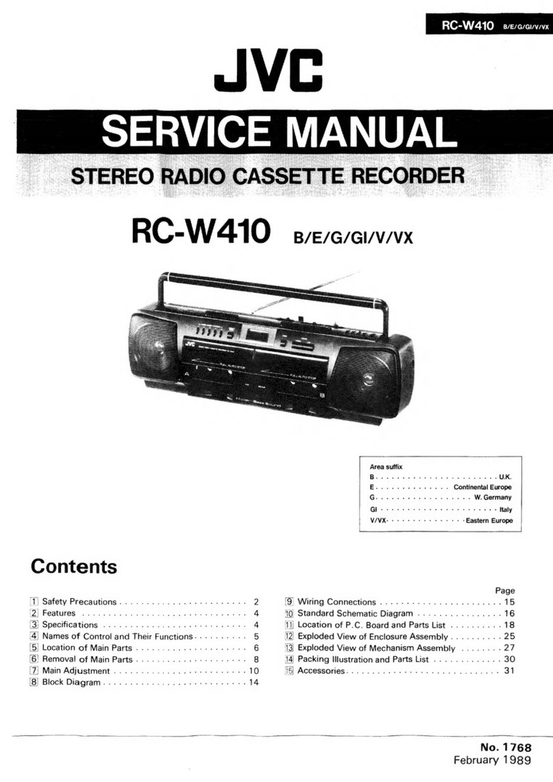
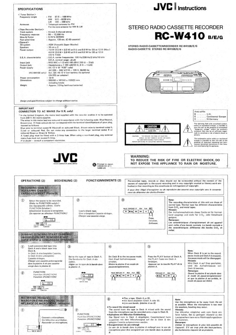
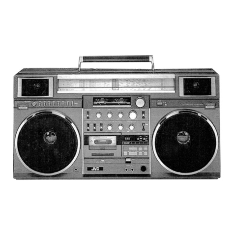
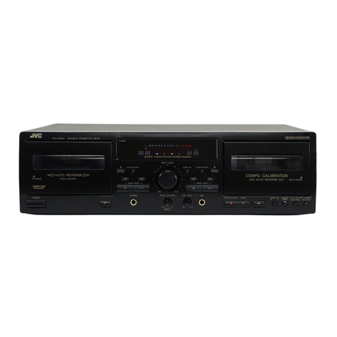
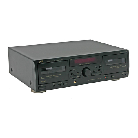
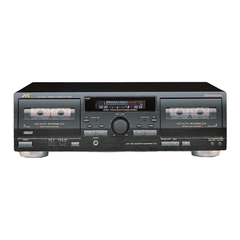
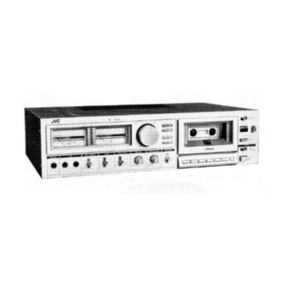
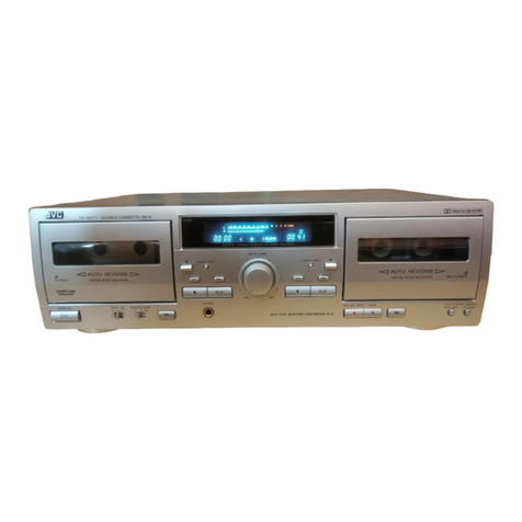
JVC TD-WS305TN A User manual

MB
TD-W305TN/-W304BK
warcrercsss
-
TD-W205TN/-W204BK
avercrevasss
TD-W77BK
c/su/TD-W75BK
cvs
JVC
SERVICE
MANUAL
TD-WS3O5TN
TD-W304BK
TD-W205TN
TD-W204BK
TD-W77BK
—cvs/u
TD-W75BK
cv
A/B/C/E/G/J/U
Area
Suffix
Bets
6
ayes
ars
Australia
Bion
ae
rege
U.K.
Cor
is,
Sanka
Be
os
ales:
Ws
Canada
E
...
Continental
Europe
Gog
58
Boat
Germany
Se
Bi
Wie
eae
tae
U.S.A.
WB
This
manual
describes
about
four
models
with
versions
of
TD-W305TN/TD-W304BK,
TD-W205TN/TD-W204BK,
TD-W77BK
and
TD-W75
together,
however,
the
contents
are
slightly
different
in
areas
as
noted
in
the
following.
e
C,
J
areas:
For
TD-W305TN/TD-W304,
TD-W205TN/TD-W204BK,
TD-W77BK
and
TD-W75BK
e
U
area:
For
TD-W305TN/TD-W304,
TD-W205TN/TD-W204BK,
TD-W77BK
e
A,B,
E,
G
areas:
TD-W305TN/TD-W304BK,
TD-W205TN/TD-W204BK
@
Main
difference
in
models
and
versions
are:
@
TD-W305TN
and
TD-W304BK:
Reverse
double-deck
type,
but
different
in
exterior
coloring
e
TD-W205TN
and
TD-W204BK:
1-way
double-deck
type,
but
different
in
exterior
coloring
e
TD-W77BK
:
Black
color.
Electric
circuits
of
TD-W305TN/TD-W304BK
are
partially
omitted.
e
TD-W75BK
:
Black
color.
Electric
circuits
of
TD-W205TN/TD-W204BK
are
partially
omitted.
®
Manual
numbers:
No.
4325
for
common
IBs
and
specifications
of
these
models
No.
4325-1
for
TD-W305TN/TD-W304BK
No.
4325-2
for
TD-W205TN/TD-W204BK
No.
4325-3
for
TD-W77BK
No.
4325-4
for
TD-W75BK

TD-W305TN/-W304BK
ABrerE/Gidsi
TD-W205TWN/-W204BK
warcyeras
TD-W77BK
ciu/TD-W75BK
cv
TD-WS3O5TN
TD-W304BK
TD-W205TN
TD-W204BK
TD-W77BK
TD-W75BK
e
For
external
appearance,
see
pages
12
and
13.
@
This
contains
common
things
for
the
above
models
and
versions.
Contents
Page
[1]
Safety
Precautions
....
2.6...
eee
ee
eee
eee
2
Dl
Pastures
vs
Canis
ee
tree
a
eee
e
eet
eee
ears
3
[3]
Instruction
Book
(Extraction).
.........e.008:
4
e
Specifications
2.6...
ee
eee
ee
eee
4
[4]
Names
of
Parts
and
Their
Functions
........--..-
8
[5]
Operation
..
6...
eee
eee
eee
eee
9
@
Playback
.
6...
ee
ee
ee
eee
9
e@
Recording
.....
2.
cee
ete
ete
eee
10
e
Dubbing
.
0...
eee
ee
tees
11
[6]
Location
of
Main
Parts
......----+e+eeeee-
12
C/J/U
A/B/C/E/G/J/U

Safety
Precau
tion
:
.
The
design
of
‘this
product
contains
special
hardware
and
many
circuits
and
components
specially
for
safety
purposes.
For
continued
protection,
no
changes
should
be
made
to
the
original
design
unless
authorized
in
writing
by
the
‘manufacturer.
Replacement
parts
must
be
identical:
to
those
uséd
in
the
original
circuits.
Service
should
be
per-
formed
by
qualified
personnel
only;
=
—
RO
pepe,
FOP
GR
os
ae
_
:
.
Alterations
of
the
design
or
circuitry
of
the
product
should.
not
be
made.
Any
design
alterations
f
the
product
.
-ushould
not’be
made.
Any
design
alterations
or
additions
will
void
the
manufacturer's
warranty
and
will
further,’
relieve
the
manufacturer
of
responsibility
for
personal
injury
or
property
damage
resulting
therefrom.
3.
Many
electrical
and-mechanical
parts
in
the
product
have
special
safety-related
characteristics.
These
characteristics
are
often
not
evident
from
visual
inspection
nor
can
the
protection
afforded
by
them
necessarily
be
obtained
by
using
replacement
components:
rated
for
higher
voltage,
wattage,
etc.
Replacement
parts
which
have
these
special
safety
characteristics
are
identified
in
the
Parts
List
of
Service
Manual.
Electrical
components
having
such
features
are
identified
by
(
A\)
on
the
Schematic
Diagram
and
Parts.
List
in
the
Service
Manual.
The
use
of
a
substitute
replacement
which
does
not
have
the
same
safety
characteristics
as
the
recommended
replacement
part
shown
in
the
Parts
List
of
Service
Manual
may
create
shock,
fire,
or
other
hazards.
|
4.
The
leads
in
the
products
are
routed
and
dressed
with-ties,
clamps,
tubings,
barriers
and
the
like
to
be
separated
from
live
parts,
high
temperature
parts,
moving
parts
and/or
sharp
edges
for
the
prevention
of
electric
shock
and
fire
hazard.
When
service
is
required,
the
original
lead
routing
and
dress
should.
be
observed,
and
it
should
be
confirmed
that
they
have
been
returned
to
normal,
after.
re-assembling.
5,
Leakage
current
check
(Electrical
shock
hazard
testing)
(USA
only)
After
re-assembling
the
product,
always
perform
an
isolation
check
on
the
exposed
metal
parts
of
the
product
(antenna
termianls,
knobs,
metal
cabinet,
screw
heads,
headphone
jack,
control
shafts,
etc.)
to
be
sure
the
product
is
safe
to
operate
without
danger
of
electrical
shock.
:
Do
not
use
a
line
isolation
transformer
during
this
check.
e
Plug
the
AC
line
cord
directly
into
the
AC
outlet.
Using
a
“Leakage
Current
Tester’,
measure
the
leakage
current
from
each
exposed
metal
part
of
the
cabinet,
particularly
any
exposed
metal
part
having
a
return
path
to
the
chassis,
to
a
known
good
earth
ground.
Any
leakage
current
must
not
exceed
0.5
mA
AC
(r.m.s.).
e
Alternate
check
method
Plug
the
AC
line
cord
directly
into
the
AC
outlet.
Use
an
AC
voltmeter
having
1,000
ohms
per
volt
or
more
sensitivity
in
the
following
manner.
Connect
a
1,500
Q
10
W
resistor
paralleled
by
a
0.15
uF
AC-type
capacitor
between
an
exposed
metal
part
and
a
known
good
earth
ground.
Measure
the
AC
voltage
across
the
resistor
with
the
er]
at
VOLTMETER
aving
1000
ohms/volt,
AC
voltmeter.
or
more
sensitivity.)
Move
the
resistor
connection
to
each
exposed
metal
part,
particularly
any
exposed
metal
part
having
a
return
path
to
the
chassis,
and
measure
the
AC
volt-
age
across
the
resistor.
Now,
reverse
the
plug
in
the
AC
outlet
and
repeat
each
measurement.
Any
voltage
measured
must
not
exceed
0.75
V
AC
(r.mss.).
This
corresponds
to
0.5
mA
AC
(r.mss.).
Good
eae
ground
0.15
uF
AC
TYPE
Place
this
probe
on
each
exposed
1500
2
10W
.
metal
part.
Warning
1.
This
equipment
has
been
designed
and
manufactured
to
meet
international
safety
standards.
2.
It
is
the
legal
responsibility
of
the
repairer
to
ensure
that
these
safety
standards
are
maintained.
3.
Repairs
must
be
made
in
accordance
with
the
relevant
safety
standards.
4
5
.
Itis
essential
that
safety
critical
components
are
replaced
by
approved
parts.
.
If
mains
voltage
selector
is
provided,
check
setting
for
local
voltage.
2
(No.
4325)

@
important
Management
Points
Regarding
Safety
.
(Items
Demanding
Special
Safety
Precautions)
“~~
a
-_———e
-
~
7
~
4
-Q905
1C901
Q903
N
@®
The
power
transformer
must
be
checked
by
the
follow-
ing
markings
as
well
as
managed
in
the
fastening
torque
of
the
screws.
Also
confirm
parts
number
according
to
the
parts
list.
:
J:
5216507
(UL
approved
No.)
C
:
VTP52A5-011F
(Marking)
@)
Power
cord
:
Make
sure
of
the
following
markings
and
inspect
exterior
scratch
and
damage.
SPT-1
KP-10
or
SU-1
SPT-1
KP-10
or
SU-1
VDE
KP-419C
BASEC
BS6500
@
Tags
to
bind
power
cords
must
be
soldered
after
being
twisted
in
order
to
prevent
them
from
coming
off.
@
The
end
of
respective
power
cords
is
soldered
in
the
air
and
the
space
from
others
must
be
3.2
mm
or
more
in
the
distance.
6)
The
strain
relief
which
is
specified
as
‘““NIFCO
2271”
Features
1.Double
auto-reverse
mechanism
for
recording/playback
in
deck
B
and
Mt
aBuog
7°
TO-W30d
-
The
DDRP
function
is
possible
oniy
when
used
with
a
suitable
JVC
CD
player.
RB303N
d>
@®
/10-W305
ony
~—
securely
fixes
the
power
cord.
©
The
primary
terminals
and
secondary
terminals
next
to
them
of
the
P.C.
board
must
not
be
stuck
out
by
the
round
end
to
keep
space
in
each
side.
Since
the
following
parts
are
heat
generating
ones,
they
must
not
contact
with
electrolytic
capacitors,
wires,
etc.
e
Parts
in
parentheses
(
)
are
inflammables.
Make
sure
of
their
lift-up
condition
for
this
purpose.
e
Parts
in
box
([_—)
are
out
of
JVC
control.
(R952),
(R919),
(R920),
(R913),
(R902),
(R901),
(R931),
(R912),
(R881),
(R875),
(RB403,
RB303)
4:
only
in
TD-W205
and
TD-W204
D902],
[R902],
[a903],
[ic90T],
[905],
[R973],
[O906],
[907],
[R937],
[Heat
sink]
R952
:
Must
not
touch
any
wire.
()
Wires
and
so
forth
must
be
securely
clamped
or
fixed
as
illustrated
on
the
left
(at
five
points)
to
keep
them
from
power
active
parts,
mobile
parts,
heating
units
and
sharp-
edged
parts.
*
:
TD-W75
has
no
need
of
this
clamp.
14,
COMPU
LINK-1/SYNCHRO
terminal
—
playback
in
deck
A
6.
Auto
tape
select
mechanism
(decks
A
*
Dolby
noise
reduction
and
HX
Pro
head-
2.
Full-logic
control
mechanism
in
both
and
B)
room
extension
manufactured
under
license
decks
7.
2-color
peak
level
indicator
from
Dolby
Laboratories
Corporation.
HX
Pro
Griginated
by
Bang
&
Olufsen.
e
High-speed
dubbing
function
reduces
tape
editing
time
by
half.
.
Dolby*
HX
PRO
headroom
extension
.
Dolby*
B
&
C
noise
reduction
system
e
Built-in
MPX
filter
.
DDRP
(Dynamics
Detection
Recording
Processor)
compatibility
8.
Synchro
start
(normal-/high-speed)
"Dolby",
the
double-D
symbol
DO
and
"HX
dubbing
PRO"
are
trademarks
of
Dolby
Laborato-
9.
Continuous
playback
ries
Licensing
Corporation.
10.
INPUT
LEVEL
control
:
.
11.
Digital
tape
counter
12.
Metal
tape
compatibility
13.
PHONES
jack
(No,
4325)
3

Instruction
Book
(Extraction)
~~
SPECIFICATIONS
(A/C/J/U-Version)
:
Stereo
double
cassette
deck
:
4-track,
2-channel
1
4.8cm
(1-7/8
inch/sec)
(Normal)
:
9.5cm
(3-3/4
inch/sec)
(High)
Frequency
response
:
(-20
dB
recording)
Metal
tape;
20
-
17,000
Hz
30
-
16,000
Hz
(+
3
dB)
Chrome
tape;
20
-
16,000
Hz
30
-
15,000
Hz
(+
3
dB)
‘Normal
tape;
20
-
16,000
Hz
30
-
15,000
Hz
(+3
dB)
:58
dB
(S
=
315
Hz,
k3
=
38%
N
=
A-weighted,
metal
tape)
The
S/N
is
improved
by
about
15
dB
at
500
Hz
and
by
max.
20
dB
at
1
kHz
~
10
kHz
with
Dolby
C
NR
on
and
improved
by
5
dB
at
1
kHz
and
by
10
dB
at
above
5
kHz
with
Type
Track
system
Tape
speed
S/N
ratio
DOLBY
B
NR
on.
{mprovement
of
14
dB
at
10
kHz
with
MOL
Dolby
C
NR
on.
Wow
and
flutter
:
0.08%
(WRMS)
Channel
separation
:
40
dB
(1kHz)
Crosstalk
:60
dB
(1
kHz)
Harmonic
distortion
:k3;
0.8%
(metal
tape,
315Hz
0
VU)
:Deck
A;
METAPERM
head
for
playback
x
1
Deck
B;
METAPERM
head
for
recording/
oe
2-gap
ferrite
jead
for
—
erasure;
Combination
head
x
1
:
Electric
governed
DC
motor
for
capstan
x
1,
DC
motor
for
reel
x
1,
DC
motor
for
mechanism
x
1
(For
both
decks
A
and
B)
Fast
forward/Rewind
:
Approx.
110
sec.
with
Heads
Motors
time
C-60
cassette
Input
lorminals
;
INE
IN
:
Input
sensitivity;
80
mV
(x
1
circuit)
(OV
;
)
Input
impedance
;
50
kQ
Output
terminals
ALINE
OUT
:
ain
level;
300
mV
(x
1
Circuit)
(0
VU)
Output
impedance;
5
kQ
PHONES
x
1
:
Output
level;
0.3
mW/
8Q(0
VU
Matching
impedance;
8Q-1k
:
COMPU
LINK-1/
SYN-
Other
terminals
:
CHRO
x
2
Power
requirement
A
version
:
AC
240
V,
50/60
Hz
C/J
version
:
AC
120V,
60
Hz
U
version
2
AC
230/127/110
V,
50/60
Hz
Power
consumption
i
ated
switch
on
With
power
switch
standby
1.6
W
Dimensions
;
(WxHxD)
1435
x
133
x
328
mm
(17-3/16
x
5-1/4
x
12-
15/16")
Weight
+
4.8
kg
(10.6
lbs.)
Accessories
+
Pin
plug
cord
..........
2
Remote
cable.........
1
Design
and
specifications
are
subject
to
change
without
notice.
4
(No.
4325)
CARACTERISTIQUES
TECHNIQUES
(version
A/C/J/U)
Type
reo
istrement
stéréo
Systémede
pistes
:4
pistes,
2
canaux
Vitesse
de
défilement
:
4,8cm/sec.
(normale)
9,5
cm/sec.(grande)
Réponse
en
fréquence:
(Enregistrement
&
-20
dB)
Bande
meétal;
.20
a
17.000
Hz
30
a
16.000
Hz
(+3
dB)
*
Bande
chrome;
20
&
16.000
Hz
30
4
15.000
Hz
(+3
dB)
Bande
normale;
20
&
16.000
Hz
30
&
15.000Hz
(+
3
dB)
:58
dB
(S
=
315
Hz,
k3
=
3%,
N
=
A-pondéré,
bande
"métai")
Le
rapport
S/B
est
amélorié
de
15
dB
env-
iron
4
500
Hz
et
de
20
dB
maximum
a
1
kHz
~
20
kHz
avec
le
Dolby
C
NR
en-circuit,
et
amélioré
de
5
dB
a
1
kHz
et
10
dB
environ
a
5
kHz
avec
le
Dolby
B
Rapport
signal/bruit
NR
en
circuit.
Amélioration
du
:4dB
a
10
kHz
avec
le
niveau
de
sortie
max.
Dolby
C
NR
en
circuit.
Pleurage
et
:0,08
%
(WRMS)
scintillement
Séparation
du
canal
:
40
dB
(1
kHz)
Diaphonie
:
60
dB
(1
kHz)
Distorsion
1k3;
0,8%
harmonique
(bande
métal,
315
Hz
0
VU)
Tétes
:
Platine
A;
téte
META-
PERM
pour
lecture
x
1
Platine
B;
téte
META-
PERM
pour
enreg-
istrement/lecture,
Téte
de
ferrite
&
double-
entrefer
pour
l'efface-
men
Téte
combinée
x
Moteurs
:
Moteur
CC
a
asservissement
élec-
tronique
pour
le
cabestan
x
1
Moteur
CC
pour
bobine
x1,
Moteur
CC
pour
méchanique
x
1
(pour
les
deux
platines
AetB
Temps
d'avance
:
Environ
110
secondes
rapide/réembobinage
avec
une
cassette
C-60
Bornes
d'entrée
LINE
IN
:
Sensibilité
d’entrée;
(x
1
circuit)
80
mV
(0
VU)
Impédance
d’entrée;
50
kQ
Bornes
de
sortie
LINE
OUT
:
Niveau
de
sortie;
(x
1
circuit)
300
mV
(0
VU)
impédance
de
sortie;
5
kQ.
PHONES
x
1
:
Niveau
de
sortie;
0,3
mW/8
Q
(0
VU)
Impédance
caracteéris-
tique;
8
Q-
1
kQ
:
Double-platine
d’enreg-
ESPECIFICACIONES
(Version
A/C/J/U)
Tipo
Sistema
de
pista
Velocidad
de
la
cinta
Respuesta
de
frecuencia
Relacion
sefial-ruido
:
Magnetofono
doble
de
cassette:
estéreo
74
pistas,
2
canales
:4,8'cm/seg.
(normal)
9,5
cmiseg.
(Alta)
:(Grabacién
a—-20
dB)
Cinta
de
metal;
220
-
17.000
Hz
30
-
16.000
Hz
(+3
dB).
Cinta
de
.cromo;
°
20
-
16.000
Hz
30
-
15.000
Hz
(+3
dB)
Cinta
normal;
20
-
16.000
Hz
30
-
15.000
Hz
(+3
dB)
:58
dB
(S
=
315
Hz,
k3
=
3%
N
=
A
pondera-
do,
cinta
metalizada)
La
relacién
S-R
se
ha
mejorado
en
aprox.
15
dB
a
500
Hz,
por
un
~
max.
de
20.dB
a
4
kHz~10:kHz
con
Dolby
C
NR
activado
yen5dB
ai
kHzy
’
en
10dB
amas
de
5
Mejora
del
nivel
de
salida
maxima
Fluctuaci6n
y
tremolaci6n
Separacion
de
canal
Diafonia
Distorsién
armonica
Cabezas
kHz
con
Dolby
B
NR
activado.
:4
dB
10
kHz
con
Doiby
C
NR
activado
:0,08
%
(WRMS)
240
dB
(1
nee
:60
dB
(1
kHz.
:k3;
0,8%
(cinta
de
metal,
315
Hz
0
VU)
:
Magnetofono
A;
Cabeza
METAPERM
pe
reproduccién
x
1,
agnetofono
B;
Cabeza
METAPERM
para
jrabacion/repro-
.
ducci3n,
Cabeza
de
ferrite
de
2
entrehier-
-
oS
para
borrado;
Motores
Tiempo
de
avance
répido/rebobinado
Terminales
de
entrada
LINE
IN
(x
1
circuito)
Terminales
de
entrada
LINE
OUT
(x
1
circuito)
PHONES
x
1
Cabeza
para
combi-
nacion
x
1
:
Motor
electrénico
de
CC
para
el
eje
de
arrastre
x
1
Motor
de
CC
para
el
Carrete
x
1
Motor
de
CC
para
de
mechanismo
x
1
(para
ambos
magneté
fonosAyB
:
Aprox.
110
segundos
con
cassette
C-60
:
Sensibilidad
de
entra-
da;
80
mV
Impedancia
de
entrada;
50
kQ2
:
Nivel
de
salida;
300
mV
(0
VU)
Impedancia
de
salida;
5
kQ
:
Nivel
de
salida;
0,3
mW/8
Q
(0
VU)
impedancia
de
salida;
8Q-1kQ

TECHNISCHE
DATEN
(G-version)
Typ
Spursystem
Bandgeschwindigkeit
:
Frequenzgang
:
Stereo-Doppel-
Cassettendeck
:4-Spur,
2-Kanal
4,8
cm/Sek.
(Normal)
9,5
cm/Sek.(High)
:
(20
dB-Aufnahme)
Metaliband;
20
-
17.0000
Hz
(DIN)
30
-
16.000
Hz
(+3
dB)
Chromband;
*
20
-
16.000
Hz
(DIN)
30
-
15.000
Hz
(+3
dB)
Normalband;
20
-
16.000
Hz
(DIN)
30
-
15.000
Hz
(+3
dB)
Signal-Rauschabstand
:58
dB
(S
=
315
Hz,
k3
Verbesserung
des
Hoéchstausgangs-
pegels
Gleichtaufschwank-
ungen
Kanaitrennung
Ubersprechdampfung:
Kiirrfaktor
Képfe
Motoren
Schnellvorlaufzeit/
Rickspulzeit
Eingange
LINE
IN:
(x1
Schaltung)
Ausgange
LINE
OUT
(x
1
Schaltung)
PHONES
x
1
=3%N=
A-gewichtige,
Metallband)
Der
Signal-Rauschab-
stand
ist
um
15
cB
bei
500
Hz
und
um
max.
20
dB
bei
1
kHz
~
10
kHz
mit
eingeschai-
tetem
DOLBY
C
NR
verbessert
und
um
5
dB
bei
1
kHz
und
um
10
dB
Uber
5
kHz
mit
LA
eagle
DOLBY
B
NR.
:4
dB
bei
Re
kHz
mit
eingeschaltetem
OLBY
C
NR.
:£0,2
%
(DIN)
:40
dB
(1
kHz)
60
ob
ae
kHz)
7
K3;
0,8%
(Nietaibane,
315
Hz
VU)
:
Deck
A;
METAPERM-
Kopf
fur
Wiedergabe
x
eck
B;
META-
PERM-Kopf
fiir
Aufnahme/Wieder-
gabe,
2-Spalt
Ferrit-
kopf
fiir
L6schen;
Kombinationskopf
x
4
:
Elektronisch
ges-
teuerter
Gleichstrom-
Motor
ftir
Kapstan
x
1
Spulen-Gleichstrom-
motor
x
1,
Gleichstrommotor
_
fir
Lautwerk
x
1
(fur
beide
Decks
A
und
B)
:
Ca.
110
Sekunden
(C-
60
Cassette)
Eingangsempfindlic-
hkeit;
80
mV
(0
VU)
Eingangsimpedanz;
50
kQ
:
Ausgangspegel;
300
mV
(0
VU)
Ausgangsimpedanz;
§
kQ
:
Ausgangspegel;
0,3
mW/8
Q
(0
VU)
Passende
Impedanz;
8Q-1k
CARACTERISTIQUES
TECHNIQUES
(Version
E)
Type
Systéme
de
pistes
:
Doubie-piatine
d’enregistrement
stéréo
:4
pistes,
2
canaux
Vitesse
de
défilement
:
4,8cm/sec.
(normale)
9,5
cm/sec.(grande)
Réponse
en
fréquence:
(Enregistrement
a
-20
dB)
Rapport
signal/bruit
Amélioration
du
niveau
de
sortie
max.
Pleurage
et
scintillement
Séparation
du
canal
Diaphonie
Distorsion
harmonique
Tétes
Moteurs
Temps
d'avance
rapide/réembobinage
Bornes
d'entrée
LINE
IN
(x
1
circuit)
Bornes
de
sortie
LINE
OUT
(x
1
circuit)
PHONES
x
1
Bande
métal;
20
&
17.000
Hz
(DIN)
30
&
16.000
Hz
(+3
dB)
Bande
chrome;
20
4
16.000
Hz
(DIN)
30
a
15.000
Hz
(43
dB)
Bande
normale;
20
a
16.000
Hz
(DIN)
30
4
15.000Hz
(+3
dB)
:58
dB
(S
=
315
Hz,
k3
=
3%,
N
=
A-pondéré,
bande
"métal")
Le
rapport
S/B
est
amélioré
de
15
dB
environ
&@
500
Hz
et
de
20
dB
maximum
a
1
kHz
~
10.
kHz
avec
Je
Dolby
C
NR
en
circuit,
et
amélioré
de
5
dB
a1
kHz
et
10 dB
environ
a5
kHz
avec
le
Dolby
B
NR
en
circuit.
:4
dB
a
10
kHz
avec
le
Dolby
C
NR
en
circuit.
:£0,2
%
(DIN)
:40
dB
(1
kHz)
:
60
dB
(1
kHz)
:k3;
0,8%
(bande
métal,
315
Hz
0
VU)
:
Platine
A;
téte
META-
PERM
pour
lecture
x
{
Platine
B;
téte
META-
PERM
pour
enreg-
istrement/lecture,
Téte
de
ferrite
a
double-
entrefer
pour
l'efface-
Tren
Téte
combinée
:
Moteur
CC
a
asservissement
elec-
tronique
pour
le
cabestan
x
1
Moteur
CC
pour
bobine
x
1
Moteur
CC
pour
mécanique
x
1
(pour
tes
deux
Seon
Aet
B)
:
Environ
110
secondes
avec
une
cassette
C-
6
:
Sensibilité
d’entrée;
80
mV
(0
VU)
Impédance
d’entrée;
50
kQ
:
Niveau
de
sortie;
300
mV
(0
VU)
Impédance
de
sortie;
5
kQ
:
Niveau
de
sortie;
0,3
mW/8
Q
(0
VU)
Impédance
caractéris-
tique;
8
Q-1kQ
SPECIFIKATIES
(Versie
E)
Type
Systeem
Bandsnelheid
Frekwentiebereik
Signaal/ruisverhouding
:
Maximaal
uitgangsniveau
Wow
en
flutter
Snelheidsfluktuaties
Overspraak
Harmonische
vervorming
Koppen
Motoren
Snelspoeltijd
Ingangen
LINE
iN
(x
1
circuit)
Uitgangen
LINE
OUT
(x
1
circuit)
PHONES
x1
74
dB
bij
:
Stereo
dubbel
casset-
tedeck
:
4-sporen,
2
kanalen
:
4,8
cm/sek.
(Normaal)
9,5
em/sek.
(Hoog)
:(-20
dB
opname)
Metaalband;
20
-
17.000
Hz
(DIN)
30
-
16.000
Hz
(+3
dB)
Chroomband;
20
-
16.000
Hz
(DIN)
30
-
15.000
Hz
(+3
dB)
Normaatband;
20
-
16.000
Hz
(DIN)
30
-
15.000
Hz
(+3
dB)
58
dB
(S
=
315
Hz,
k3
=
3%
N
=
A-gemeten,
metaalband)
De
signaal/ruisver-
houding
wordt
met
ca.
15
dB
bij
500
Hz
ver-
beterd.
Bij
1
KHz~10
kHz
met
de
DOLBY
C
NR
op
“ON”
wordt
de
signaal
ruisverhouding
met
max.
20
dB
ver-
beterd.
De
signaal
/ruisverhouding
wordt
met
5
dB
bij
1
verbeterd
en
‘met
10
dB
bij
meer
dan
5
kHz,
als
de
Dolby
B
NR
schakelaar
tegeli-
jkertijd
op
“ON”
staat.
10
kHz
met
Dolby
C
NR
op
“ON”
:40;2%
:40
dB
(1
kHz)
:60
dB
(1
kHz)
£3;
0,8
%
(metaalband,
315
Hz
OV
U
:
Deck
A;
METAPERM-
kop
voor
weergave
x
1,
Deck
B;
META-
PERM-kop
voor
opname/weergave,
ferriet
wiskop
met
dubbele
spleet;
Kombinatiekop
x
1
:
Elektronisch
gestu-
urde
gelijkstroommo-
tor
voor
de
aandrijving
van
de
capstan
x
1
Gelijk
—
stroommotor
voor
spel
x
1
Gelijk
stroommotor
voor
mechanisme
x
1
peer
deck
A
en
deck
:Ca.
110
sek.
met
een
C-60
cassette;
:Invoergevoellgheid;
80
mV
(0
VU)
Ingangsimpedantie;
50
kQ
:
Uitgangsniveau;
300
mV
(0
VU)
pe
aempenames
:
Uitgangsniveau;
0,3
mMW/8
Q
(0
VU)
Geschikte
impedantie;
8Q-1kQ
(No.
4325)
5

TEKNISKA
DATA
(Version
E)
Typ
Sparsystem
Banhastighet
Frekvensomfang
Stdravstand
Férbattring
av
max
utniva
Svaj
Kanalseparation
Overhérning
Harmonisk
distorsion
Tonhuvuden
6
(No.
4325)
:
Dubbelt
strereokasset-
dack
:
4
spar,
2
kanaler
:
4,8
cm/sek
(normal
hastighet)
9,5
cm/sek
(hég
hastighet)
:
(-20
dB
inspelning)
Metalitband;
20
—
17.000
Hz
(DIN)
30
—
16.000
Hz
(+
3
dB)
Kromband;
20
—
16.000
Hz
(DIN)
30
—
15.000
Hz
(+
3
dB)
Normalband;
20
—
16.000
Hz
(DIN)
30
—
15.000
Hz
(+3
dB)
:
58
dB
(S
=
315
Hz,
k3
=
3%
N
=
A-vagt,
met-
allband)
Stéravstandet
férbat-
tras
med
omkring
15
dB
vid
500
Hz
och
med
max.
20
aB
vid
4
kHz
—-
10
kHz
med
Dolby
C.
Det
for
bat-
tras
med
5
dB
vid
1
kHz
och
med
10
dB
vid
éver
5
kHz
med
Dolby
B.
:
4
dB
vid
10
kHz
med
Dolby
C
=
+0.2%
(DIN)
:40
dB
(1kHz)
=
60
dB
(1
kHz)
2
k3;
0,8%
(metaliband,
315
Hz
0
VU)
:
Dack
A;
METAPERM
huvud
fér
avspeining
x
1,
Dack
B;
META-
PERM
huvud
fér
Autres
prises
“COMPU
LINK-1
/SYNCHRO
x
2
Alimentation
‘
Version
A
:
240
V
CA,
50/60Hz
Version
C/J
:
120
V
CA,
60
Hz
Version
U
:230/127/110
V
CA,
50/60
Hz
Consommation
:17
W
avec
alimenta-
tion
en
circuit
1,6
W
avec
alimenta-
tion
hors
circuit
Dimensions
(Lx
Hx
P)
2435
x
133
x
328
mm
Poids:
4,8
kg
Accessoires:
Fil
€
broches...........
2
Fil
de
télécommande....1
Otros terminales
:
COMPU
.LINK-4
ISYNCHRO
x
2
Alimentacion
Version
A
:
CA
240
V,
50/60
Hz
Version
C/J
:
CA
120
V,
60
Hz
Version
U
:
CA
230
/127/110
V,
50/60
Hz
Consumo
:
17
W
encendido
1,6
W
apagado
Dimensiones
(An
x
Al
x
F)
:
435
x133
x
328
mm
Peso
:
4,8
kg
Accesorios
:
Cordones
con
clavijas
t
eesndaseesiiesctaaevenensseaeee
2
Cable
de
mando
a
dis-
TANCIA
oo...
eee
1
Présentation
et
caractéristiques
modifiables
El
disefio
y
las
especificaciones
estan
sujetos
sans
préavis
a
cambio
sin
aviso.
in/avspelning,
2
spalts
feriithuvud
vor
radering;
Kombinationshuvud
x
1
Motorer
:
Elektroniskt
styrd
lik-
strémsmotor
fér
kap-
stan/spole
x
1
Likstromsmotor
fér
sna
bbspoining
x
1
Likstr6msmotor
for
fack
x
1
(Fér
bade
dack
A
och
B)
Snabbspolningstid
:Ca
110
sek.
(C-60
kassett)
Ingangar
LINE
IN
:
Inkanslight;
(x
1
krets)
80
mV
(0
VU)
Ingangsimpedans;
50
kQ
Utgangar
LINE
OUT
:
Utgangsniva;
300
mV
(0
VU)
(x
1
krets)
Utgangsimpedans;
5
kQ
PHONES,
1
st
:
Utgangsniva;
0,3
mW/8
Q
(0
VU)
Passande
impedans;
8Q-1kQ
Andra
kontakter
:
COMPU
LINK-1/
SYN-
CHRO
x
2
Strémart
:
~
230
V,
50/60
Hz
Effecktforbrukning
:
17
W
(Standby-lage;
1,6
W)
Matt
(B
x
H
x
D)
1435
x133
x
328
mm
Vikt
14,8
kg
Tillbehér
:
Kabel
med
stiftpluggar
ncteaesestuaivamvoseester
taut
2
Raitt
till
Andringar
férbehalles.

Weitere
Anschllisse
Spannungsversorgung
-
Leistungsaufnahme
Abmessungen
(BxHxT)
Gewicht
Zubehér
:
COMPU
LINK-1
/SYN-
CHRO
x
2
Netz
230
V,
50/60
Hz
:17
W
bei
Betrieb
1,6
W
bei
Betriebsbe-
reitschaft
2435
x
133
x
328.
mm
14,8
kg
:
Chinchkabel
2
Fernbedienkabel
....
1
Technische
Anderungen
vorbehalten
!
SPECIFICATIONS
(B-version)
Type
:
Stereo
double
cassette
deck
Track
system
:4-track,
2-channel
Tape
speed
:4.8cm
(1-7/8
inch/sec)
Frequency
response
S/N
ratio
Improvement
of
MOL
Wow
and
flutter
Channel
separation
(Normal)
:9.5cm
(3-3/4
inch/sec)
High
:
("58
de
recording)
Metal
tape;
30
-
16,000
Hz
(+
3
dB)
Chrome
tape;
30
-
15,000
Hz
(+
3
dB)
Normal
tape;
30
-
15,000
Hz
(+
3
dB)
:58
dB
(S
=
315
Hz,
k3
=
3%
N
=
A-weighted,
metal
tape)
The
S/N
is
improved
by
about
15
dB
at
500
Hz
and
by
max.
20
cB
at
1
kHz
~
10
kHz
with
Dolby
C
NR
on
and
improved
by
5
dB
at
1
kHz
and
by
10
dB
at
above
5
kHz
with
DOLBY
B
NR
on.
:4
dB
at
10
kHz
with
Dolby
C
NR
on.
:£0.2%
(DIN)
:60
dB
(1kHz)
Autres
prises
Alimentation
_
Consommation
-
Dimensions
(Lx
H
x
P)
Poids:
Accessoires:
:
COMPU
LINK-1
ISYNCHRO
x
2
:230
V
CA,
50/60
Hz
=
117°W
avec
alimenta-
tion
en
circuit
a,
1,6
W
avec
alimenta-
tion
hors
circuit
:435
x133
x
328
mm
.
4,8-kg
«Fil
&
broches.............
2
Fil
de
télécommande....1
Présentation
et
caractéristiques
modifiables
sans
préavis
Crosstalk
Harmonic
distortion
Heads
:40
dB
(1
kHz)
:k3;
0.8%
(metal
tape,
315
Hz
0
VU):
:Deck
A;
METAPERM
head
for
playback
x
1
Deck
B;
METAPERM
head
for
recording/
playback,
2-gap
ferrite
head
for
erasure;
-Combination
head
x
1
Motors
Fast
forward/Rewind
:
time
Input
terminals
LINE
IN
(x
1
circuit)
Output
terminals
LINE
OUT
(x
1
circuit)
:
Electric
governed
DC
motor
for
capstan
x
1
DC
motor
for
reel
x
1
DC
motor
for
mechanism
x
1
(For
both
decks
A
and
B)
Approx.
110
sec.
with
C-60
cassette
:
Input
sensitivity;
80
mV
(0
VU).
Input
impedance;
50
kQ
:
Output
level;
300
mV
(0
VU)
Output
impedance;
5
kQ
_
Stroomverbruik
Andere
aansluitingen
:
COMPU
LINK-1
ISYNCHRO
x
2
:230
V
wisselstroom,
50/60
Hz
:
Met
toestel
aan;
17
W
Met
toestel
uit-
geschakeld;
1,6
W
Netspanning
Afmetingen
2435
x
133
x
328
mm
-(BxHxD)
Gewicht
—
74,8
kg
Toebehoren
:Penstekkersnoer
oseuteducaseasateazavsesoeetis
2
Afstandsbedienings-
Kabol.s
siciisessiraie
1
Wijzigingen
in
ontwerp
en
specifikaties
voor-
behouden.
PHONES
x
1
:
Output
fevel;
0.3
mW/
82
(0
VU),
Matching
impedance
;
8Q-1kQ
:
COMPU
LINK-1/
SYNCHRO
x
2
:
AC
240
V,
50/60
Hz
:
With
power
switch
on
7W
Other
terminals
Power
requirement
Power
consumption
With
power
switch
standby
1.6
W
Dimensions
(W
xH
x
D)
1435
x
133
x
328
mm
Weight
14.8
kg
Accessories
:
Pin
plug
cord
..........
2
Remote
cable.........
1
Design
and
specifications
are
subject
to
change
without
notice.
(No.
4325)
7

[4]
Names
of
Parts
and
Their
Functions
@
POWER
switch
©
Cassette
holder
(deck
A)
©
A
DECK
EJECT
button
@
Indicators
DECKA
“«<
:
This
lights
when
rewinding
the
tape
right
to
left.
PLAY
:
This
lights
when
in
the
playback.
>>
:.
This
lights
when
rewinding
the
tape
left
to
right.
@,»:
Indicates
the
direction
of
tape
travel.
HIGH
DUB
>
:
This
lignts
when
in
the
high-speed
dubbing.
DUB»
:
This
lights
when
in
the
normal-speed
dubbing.
DDRP
:
Lights
when
in
DDRP
operation
mode.
c2)
_:
Indicates
reverse
mode.
DECK
B
<<
:
This
lights
when
rewinding
the
tape
right
to
left.
PLAY
:
Lights
when
the
unit
is in
the
playback
and
record
modes.
This
flashes
when
in
the
record-
pause
mode.
>>
:
This
lights
when
rewinding
the
tape
left
to
right.
REC:
Lights
when
the
unit
is
in
the
record
and
record-pause
modes;
blinks
during
record
muting.
“,®
:
Indicates
the
direction
of
tape
travel.
©
PEAK
LEVEL
INDICATOR
These
indicators
fight
according
to
the
level
of
the
signal
being
recorded
or
the
level
of
the
signal
recorded
on
the
tape.
Note:
0
dB
:
IEC
(DIN)
STANDARD
LEVEL
(250
nWb/m)
0
VU
:
EIAJ
STANDARD
LEVEL
(160
nWb/m)
Da
:DOLBY
NR
STANDARD
LEVEL
@
B
DECK
EJECT
buiton
@
Cassette
holder
(deck
B)
©
INPUT
LEVEL
control
8
(No.
4325)
©
Digital
counter
(A
or
B)
setting
button
When
this
button
is
pressed,
the
digital
counter
indicator
changes
between
deck
Aand
B.
@
Digital
counter
‘The
“A”
indicator
lights
during
counter
indication
of
deck
A.
The
indicator
goes
off
during
counter
indication
of
deck
B.
When
the
power
is
‘turned
on,
the
digital
counter
displays
the
status
of
deck
B.
When
the
power
is
turned
off,
the
counter
is
cleared.
@
Counter
RESET
button
Press
this
button
to
set
the
digital
counter
to
"0000"
@
REVERSE
MODE
switch
Select
the
single
side
or
full
record/play-
back
mode,
or
the
continuous
play
mode.
(See
page
31.)
e=@
:
For
single-side
recording
or
play-
back.
e
=:
To
play
or
record
both
sides
A
and
B.
eC
:
To
play
sides
A
and
B
continuous-
ly.
@
PHONES
jack
Connect
headphones
(with
an
impedance
of
8Q
to
1
kQ).
@
Cassette
operation
buttons
(deck
A)
<i>
(direction):
Press
to
change
the
direction
of
tape
travel.
<<
:Press
to
wind
the
tape
quickly
from
right
to
left.
PLAY:Press
to
play
the
tape.
>>
:Press
to
wind
the
tape
quickly
from
left
to
right.
ll
(stop):
Press
to
stop
the
tape.
(The
tape
automatically
stops
when
it
reaches
the
end.)
@
A>
BSYNCHRO
DUBBING
button
e
NORM
SPEED:
Press
to
perform
nor-
mal-speed
dubbing.
«
HIGH
SPEED:
Press
to
perform
high-
speed
dubbing.
@
DOLBY
NR
switch
Set
to
B
or
C
for
recording
using
the
Dolby
NR
system
or
for
playing
back
a
tape
that
was
recorded
using
the
Dolby
NR
system.
Set
to
OFF
when
the
Dolby
NR
system
is
not
used.
@
Cassette
operation
buttons
(deck
B)
ii
PAUSE:
Press
to
stop
the
tape
tem-
porarily
during
recording
and
play-
back.
Press
the
PLAY
button
to
release
the
pause mode.
©
REC/REC
MUTE:
Press
the
PLAY
but-
ton
while
pressing
this
button
to
_
Start
recording,
and
press
to
leave
an
appropriate
non-recorded
sec-
tion.
(See
page
23.)
@
(stop):
Press
to
stop
the
tape.
Also
press
to
stop
both
decks
simul-
taneously
during
dubbing.
<<:
Press
to
wind
the
tape
quickly
from
right
to
left.
PLAY:
Press
to
start
recording/playback.
>>:
Press
to
wind
the
tape
quickly
from
left
to
right.
<i>
(direction):
Press
to
change
the
direc
tion
of
tape
travel.

Operation
PLAYBACK
POWER
=
TANDBY
DOLBY
NR
<i>
B
OFF
C
Playback
of
deck
A
Operate
in
the
order
of
the
numbers
in
the
illustration.
@
Press
the
POWER
switch
to
set
to
ON
(=).
@
Load
a
prerecorded
cassette
with
side
A
facing
out.
©
Select
the
side
to
be
played
back.
Side
A...
Forward
direction
(PLAY
>>)
Side
B...
Reverse
direction
(@
PLAY)
@
Set
the
DOLBY
NR
switch
to
the
same
position
as
when
the
tape
was
recorded.
@
Select
the
REVERSE
MODE.
(See
page
31.)
@
Press
the
PLAY
button
of
deck
A
to
start
playback.
REVERSE
MODE
ee
[tH]
<_>
Playback
of
deck
B
Perform
steps
@
to
@
of
the
above
proce-
dure
for
deck
B.
Continuous
play
First
set
the
REVERSE
MODE
switch
to:c%..
Load
cassette
tapes
in
both
decks
and
press
the
PLAY
button
of
the
deck
to
be
played
first
for
continuous
play
of
both
decks.
«
When
playback
in
the
reverse
direction
ends,
the
deck
switches
to
the
standby
mode
in
the
forward
direction.
At
this
time,
the
other
deck
starts
playback.
This
oper-
ation
is
repeated
between
decks
A
and
B.
While
one
deck
is
playing
back,
the
cas-
sette
in
the
other
one
can
be
replaced.
This
is
convenient
to
the
long-time
play-
back
of
background
music.
e
Press
the
ll
(stop)
button
of
the
deck
that
is
running
to
stop
continuous
play.
Note:
e
Use
recorded
tapes
with
the
same
noise
reduction
mode
in
decks
A
and
B.
PLAY
(No.
4325)
9

RECORDING
Operate
in
the
order
of
the
numbers
in
the
illustration.
;
e
Make
sure
the
safety
tab
of
the
cassette
has
not
been
broken
off.
Deck
B
only
Nur
Deck
B
Platine
B
seulement
Alleen
deck
B
Magnetdofono
B
solamente
QO
_x2
2]
DOLBY
NR
REVERSE
MODE
e
B
OFF
C
>
Dect
+
<
_
ep
3)
—_
@
Press
the
POWER
switch
to
set
to
ON
(=).
@
Load
a
cassette
for
recording.
@
Set
the
DOLBY
NR
switch
as
required.
@
Select
the
REVERSE
MODE.
(See
page
31.)
@
Select
the
side
to
be
recorded.
@
Press
the
i
PAUSE
button
and
O
REC/REC
MUTE
button
(record-pause
mode}.
REC
lights
and
PLAY
indicator
flashes.
@
Adjust
the
recording
level.
(See
page
25.)
@
Press
to
“0000”.
©
Press
the
PLAY
button
to
start
recording.
WARNING
It
may
be
unlawful
to
record
or
playback
copyrighted
material
without
the
consent
of
the
copyright
owner.
10
(No.
4325)
DDRP
(Dynamics
Detection
Recording
Processor)
recording
DDRP
recording
is
performed
with
suitable
JVC
CD
players
and
the
recording
level
adjustment
is
performed
automatically.
Since
recording
tevel
adjustment
is
performed
automatically
for
different
types
of
tape
(nor-
mal,
CrOz
and
metal),
the
adjustment
of
INPUT
LEVEL
control
is
not
required.
Read
the
instruction
book
of
your
CD
player
carefully.
Erasing
When
recording
on
a
prerecorded
tape,
the
previous
recording
is
automatically
erased
and
only
the
new
program
is
recorded
on
the
tape.
To
erase
a
tape
without
making
a
new
record-
ing...
Follow
the
section
“RECORDING”
but
in
step
@,
set
the
INPUT
LEVEL
contro!
to
MIN.
|
DDRP
(Dynamics
Detection
Recording
Processor)
recording
The
DDRP
function
makes
possible
fully
automatic
recording
when
used
with
a
suit
able
JVC
CD
player.
When
the
DDRP
button
of
a
suitable
JVC
CD
player
is
pressed,
the
’
recording
level
is
first
adjusted
automatically,
then
recording
starts;
it
is
not
necessory
to
start
recording
by
the
normal
procedure.
Notes:
¢
Synchronized
recording
or
DDAP
record-
ing
stops
automatically
when
the
CD
play-
er
stops
playing.
e
Synchronized
recording
does
not
start
except
when
the
record-pause
mode
is
set
by
simultaneously
pressing
the
O
REC/REC
MUTE
and
&l
PAUSE
buttons
in
the
stop
mode.
¢
To
cancel
synchronized
recording
or
DDRP
recording,
press
the
STOP
button
of
the
CD
player
or
cassette
deck.
¢
The
source
is
locked
to
the
CD
position
during
synchronized
recording
or
DDRP
recording
to
avoid
accidental
stops
or
switch-over
to
another
component.
To
switch
over
the
components,
cancel
syn-
chronized
recording
or
DDRP
recording
first.
The
INPUT
LEVEL
control
does
not
function
during
DDRP
recording.

DUBBING
B-DECK
EJECT
e
Synchro
dubbing
@
Press
the
POWER
switch
to
set
to
ON
(
=
).
@
Insert
a
prerecorded
tape
into
deck
A
with
side
A
facing
out
and
press
the
<I>
(direc-
tion)
button
to
select
the
travel
direction.
@
Insert
the
blank
tape
with
side
A
facing
out
into
deck
B,
and
press
the
I>
(direction)
button
to
select
the
side
to
be
recorded.
-
@
Press
to
“0000”.
@
Press
the
SYNCHRO
DUBBING
(NORM
or
HIGH
SPEED)
button
to
start
dubbing.
@
Press
the
Ml
(stop)
button
of
deck
B
to
stop
dubbing.
When
deck
B
stops,
the
dubbing
mode
is.
automatically
released.
e
Synchro
record
muting
When
deck
A
stops
or
enters
any
mode
other
than
the
playback
mode
during
dub-
bing,
deck
B
enters
the
record
mute
oper-
ation
automatically
and
then
enters
the
record-pause
mode.
«
Before
pressing
the
SYNCHRO
DUB-
BING
button
Confitm
that*deck
B
is
in
the
stop
mode
before
starting
dubbing.
Dubbing
and
DOLBY
NR
switch
During
dubbing,
the
same
NR
mode
selected
for
the
playback
cassette
is
applied
to
the
recording
cassette,
regardless
of
the
position
of
the
NR
switch.
Input
level
Recording
is
performed
at
the
same
level
as
the
playback
tape
during
dubbing
regardless
of
the
position
of
the
INPUT
LEVEL
control.
rT
a
rc
~
[~~
—_
~
a
APBSYNCHRO
DUBBING
HIGH
SREED
.
pre
editing
.
Press
the
©
REC/REC
MUTE
button
when
finished
dubbing
a
tune.
Deck
B
automatically
enters
the
record
muting
mode
and
leaves
a
non-recorded
section
of
about
4
seconds
then
enters
the
record-pause
mode.
2.
Press
the
I
(stop)
button
of
deck
A
and
search
for
the
next
tune
you
want
by
using
the
>>
,
««,
or
PLAY
button.
Then
stop
the
cassette
just
before
the
begin-
ning
of
the
tune.
3.
Press
the
same
SYNCHRO
DUBBING
but-
ton
pressed
before
ihe:
pause
again,
and
dubbing
will
start.
:
Notes
at
dubbing
1.
Normal-speed
dubbing
is
recommended
to
obtain
good
sound
quality.
2.
Television
receivers
placed
close
to
the
deck
may
cause
interference
on
the
recorded
signal
when
the
deck
is
used
in
the
high-speed
dubbing
mode.
If
this
hap-
pens,
either
turn
off
the
television
receiver
or
use
the
normal-speed
dubbing
mode.
@
e
POWER
-
TANDBY
cle
3
5
wt
e0
(No.
4325)
11

[6]
Location
of
Main
Parts
©
TD-W305TN
Power
Transformer
Main
Body
Ass’y
Reverse
Mechanism
Direction
Switch
Direction
Switch
Reverse
Mode
Switch
FL
Board
Ass‘y
Power
Switch
Ass’y
Leaf
Switch
Board
Ass’y
Leaf
Switch
Board
Ass’y
Mechanism
|B]
Ass’y
Machanism
Ass’y
©
TD-W205TN
Power
Transformer
Main
Body
Ass‘y
1-way
Mechanism
Headphone
Jack
FL
Board
Ass’
.
Power
Switch
Ass‘y
.
Leaf
Switch
Board
Ass’y
Leaf
Switch
Board
Assy
Mechanism
Ass'y
Mechanism
Ass'y
12
(No.
4325)

@®
TD-W75BK
Power
Transformer
Main
Body
Ass’y
Direction
Switch
Direction
Switch
Reverse
Mode
Switch
FL
Board
Ass’y
;
;
Power
Switch
Ass’y
Leaf
Switch
Board
Ass'y
Leaf
Switch
Board
Ass’y
Mechanism
|B}
Assy
Machanism
Ass’y
©
TD-W77BK
Power
Transformer
Main
Body
Ass’y
Headphone
Jack
FL
Board
Ass’y
Ree
SOMES
ROY
Leaf
Switch
Board
Ass’y
Leaf
Switch
Board
Ass’y
Mechanism
B
Ass'y
Mechanism
Ass'y
(No.
4325)
13

Mi
1C701
MB88514B-1366T
VV
VY
rail
mis
|
efile
pNaga0
@)
|
é
B
A,
PLAY
SPEED
B.
PLAY
SPEED
alt
re}
TT
5)
ajul8
lea
>
oe
ai
ile
Se
eo
g—L.
LEVEL
ah
R,
LEVEL
BUGBRUE
r=
£
E
SSS
B. F.
REEL
A. R.
DOOR
B.
F.
DOOR
B.
R.
DOOR
Q44
B.
Re
CAM
B.
F.
CAM
A.
Ae
REEL
A.
Fs
REEL
;
Av
Re
CAM
FePt=|
oo
|
b>
A.
F.
CAM
BIAS
raTee|
|
EC
a4
|
rial
os
BMS:
A.
F.
DOOR
laa
|
os
|
14
(No.
4325)

PIN
FUNCTION
PIN
ACTIVE
:
:
as
PORT
SIGNALNAME
|‘VEVyer
FUNCTION/OPERATION
1
EO
GO
H
-
FL
GRID
OUTPUT
(used
in
common
with
DYNAMIC
SCAN
SELECT
OUTPUT)
H
2
-
FL
ANODE
OUTPUT
(For
segment
arrangement,
see
ports
location
diagram.)
H
MECHANISM
A
PB
AMP.
SWITCHING
OUTPUT
Mechanism
A
in
PB:
“’H”
H
MECHANISM
B
PB
AMP.
SWITCHING
OUTPUT
Mechanism
B
in
PB:
“H”
H
In
Dubbing
mode
(both
in
Normal
speed
dubbing
and
High
speed
dubbing)
:
‘‘H”’
4
In
High
speed
dubbing
:
“L”
CLOCK
OUTPUT
for
Port
Expander
(clock
pulse
width
:
500
ns
or
more.
)
(For
timing,
see
another
section.)
DDRP
AMP
SWITCHING
OUTPUT
ON:
“H"
OFF:
“L”
®
With
input
of
DCS
““B6’":
ON
®@
With
input
of
DCS
’B7"'/At
the
end
of
Recording
:
OFF
@
When
DDRP
of
DYNAMIC
SCAN
INPUT
is
‘H”
:
No
operation
DATA
OUTPUT
for
Port
Expander
(For
timing,
see
another
section.)
MUSIC
DETECTION
INPUT
for
Music
Scan.
When
requested
music
is
detected
:
'’H”
[Music
Detection
Time]
@
Presence
(being
played)
of
requested
music
is
judged
when
’‘H”’
continues
for
150
msec
or
longer
after
‘’L”’
period
of
10
msec
or
longer.
e@
Absence
(play
finishes)
of
requested
music
is
judged
when
“L”
continues
for
10
msec
or
longer
after
’’H”
period
of
150
msec
or
longer.
e@
Music
detection
is
prohibited
for
200
msec
after
MS
mode
starts.
@
No
operation
in
W305/W205
mode.
33
|
RO
A.F.
CAM
NORMAL
ROTATION
OUTPUT
of
Mechanism
A
Cam
Motor.
R.
PLAY
>
F.
PLAY
:
“H”
28
E24
CLOCK
le
oe
DDRP
H
S
ieen
30
E26
DATA
31
E27
MS
SIG
H
34
A.R.
CAM
H
REVERSE
ROTATION
OUTPUT
of
Mechanism
A
Cam
Motor.
F.
PLAY
>
R.
PLAY
:
“H”
ae
NORMAL
ROTATION
OUTPUT
of
Mechanism
A
Reel
Motor.
F.
PLAY,
“D>”:
“H”
36
A.R.
REEL
REVERSE
ROTATION
OUTPUT
of
Mechanism
A
Reel
Motor.
R.
PLAY,
*<k]”
:
““H”
37
|
R4
B.F.CAM
|
_H__-|
NORMAL
ROTATION
OUTPUT
of
Mechanism
B
Cam
Motor.
R.
PLAY
>
F.
PLAY
:
“H”
[ss
|
R5
|
B.R.cAM
|
H__
|
REVERSE
ROTATION
OUTPUT
of
Mechanism
8
Cam
Motor.
F.
PLAY
>
R.
PLAY
:
“H’’
39
R6
B.F,
REEL
H
NORMAL
ROTATION
OUTPUT
of
Mechanism
B
Reel
Motor,
F.PLAY,
*DD>”:
“H”
40
R7
B.R.
REEL
H
REVERSE
ROTATION
OUTPUT
of
Mechanism
B
Reel
Motor.
R.
PLAY,
*<KI”:
“H"
41
E37
DCS
IN
L
DCS
INPUT.
Inverted
input
signal
of
DCS
line
(For
detail,
refer
to
another
section.)
42
E36
DCS
OUT
L
DCS
OUTPUT.
Externally
interverted
output.
(For
detail,
refer
to
another
section.)
47
E35
B.
PLAY
SPEED.
H
Mechanism
B
REEL
MOTOR
REGULATION
OUTPUT
(SPEED
CONTROL}
When
Mechanism
B
in
PLAY,
REC/PLAY,
REC
MUTE,
N.S.
DUB,
H.S.
DUB
:
“H’”’
48
E34
A.
PLAY
SPEED
H
Mechanism
A
REEL
MOTOR
REGULATION
OUTPUT
(SPEED
CONTROL)
When
Mechanism
A
in
PLAY,
N.S.
DUB,
H.S.
DUB:
“H”
ae
iol
Diet
—
|Reh
)
eVEL
METER
A/D
INPUT
(For
detail,
refer
to
another
section.)
54
|
ANO
L.
LEVEL
-
L-ch
55
R8
B.
CPLS
MECHANISM
B
COUNTER
PULSE
INPUT
:
;
:
]
for
Reel
End
Detection,
Electronic
Counter
56
RQ
A.
CPLS
MECHANISM
A
COUNTER
PULSE
INPUT
@
Pulse
whose
minimum
edge
width
is
3.5
msec
must
be
received
without
fail.
@
Auto
Stop
Period:
When
COUNTER
PULSE
does
not
vary
in
reel
motor
rotation
for
the
following
period,
Auto
Stop
mode
takes
place:
In
Fast
Foward
operation
(
<j,
DD
,
MS):
1.5
sec
{in
Normal
operation
(PLAY,
REC/PLAY)
:
15
sec
In
normal
operation,
counting
is
not
operated
for
3.5
sec
after
start
of
reel
motor
and
auto
stop
takes
place
1.5
sec
after
the
non-counting
period
for
3.5
sec.
(No.
4325)
15

EXPLANATION
OF
FL601
Respective
indications
by
the
FL
indicator
are
as
shown
in
the
figure.
When
all
or
some
indications
do
not
go
on,
inspect
the
cause
in
the
following
manner.
1.
Confirm
power
supply
to
F1
and
F2.
2.
When
characters/symbols
shown
in
the
figure
do
not
light,
check
up
according
to
the
anode
and
grid
matrix
table.
[f
both
anode
and
grid
have
high
potential,
it is
considered
that
the
condition
is
generally
good
and
the
trouble
results
from
fault
in
the
FL
tube.
terminal
of
the
FL
tube.
4.
Example
of
trouble:
G4
L
dB
#20
2
«=6©10
siz6
4/0VU
2
DO
O
2
+4
R
[A]
HIGH
DUB
[BJ
44s:
S72
>
DDRP
44
REC
pp®
<4
PLAY
B>C
4—
)
<4
PLAY
b>
$3
$4
S6
$5
6$9
Sjo0
G3
ANODE
CONNECTION
>
a
a
Qa
yl
rl]
>rie
‘
OT
Ni=
nD
bh
w
fee]
N
&
&
Ag
=
rs)
JVC
VICTOR
COMPANY
OF
JAPAN,
LIMITED.
AUDIO
PRODUCTS
DIVISION
MAEBASHI
PLANT
“PLAY”
does
not
light.
Make
sure
of
high
level
both
at
A5
and
G3.
10-1,
1-chome,
Ohwatari-cho,
Maebashi-city
371,
Japan
@
3.
Measurement
of
terminal
voltage
should
be
done
at
the
Printed
in
Japan
—H0212
—S—

TD-W304BK/-W305TN
wercreven
TD-W304BK
TD-W305TN
wercre/av
SERVICE
MANUAL
STEREO
DOUBLE
CASSETTE
DECK
No.
4325-1
TD-W305
and
TD-W304
are
the
same
model
but
different
only
in
the
exterior
coloring.
TD-W305
is
in
titanium
color
while
TD-W304
is
in
black.
For
servicing,
refer
to
the
parts
comparison
table
on
page
22.
Contents
Page
:
Page
[1]
Removal
of
Main
Parts.
..........50
202200
ee
2
[6]
Location
of
Main
Board
Parts
and
Parts
List
.....
16
e
Enclosure
Section
.........
2.020
eee
eee
2
ao
Main
Board
fox
cs
ea
Gs
dhabewe
Red
towws
16
e
Mechanism
Section...
......
0000
eee
eee
4
e
Other
Board/Power
Supply
Board
...........
20
[2]
Main
Adjustments...
6...
6.
eee
ee
eee
ee
eens
8
[7]
Exploded
View
of
Enclosure
Assembly
.........
21
[8B]
Block
Diagram
1.1...
eee
eee
ee
eee
ee
12
[8]
Exploded
View
of
Mechanism
Component
Parts...
24
[4]
Wiring
Connections
.....
2...
eee
eee
eee
13
[GS]
Packing...
2...
eee
ee
ee
ett
25
[5]
Standard
Circuit
Diagram
........-.--
ee
eee
14

[1]
Removal
of
Main
Parts
©
~
Wi
Enclosure
Section
ola:
So
™
Top
cover
1)
Remove
four
screws
@
retaining
the
top
cover
from
both
sides.
2)
Remove
two
screws
@)
retaining
the
top
cover
from
the
back
side.
;
®
Front
panel
assembly.
1)
Remove
the
top
cover.
2)
Remove
two.
screws
retaining
the
foot.
of
the
front
side.
:
ae
3)
Remove
four
screws
3)
retaining
the
mechanism
holder
to
chassis.
4)
Remove
three
screws
@
retaining
the
front
panel
ass’y
from
bottom
side.
;
5)
Release
the
front
panel
ass’y
from
two
pawls
in
the
front
and
bottom
sides
and
draw
it
to
the
front
side.
:
8p
™
Mechanism
assembly
24
Main
Board
@—{15)
(for
deck
A
anddeck
B
in
common)
ae
Although
the
mechanism
assembly
can
be
removed
without
eo
detaching
the
front
panel
ass’y,
it is
recommended
to
de-
2
CNS
RENCE
tach
the
front
panel
ass’y
to
do
the
work
with
ease.
5
Geni
eNO
AINE
ones
1)
Remove
four
screws
®
and
©)
or)
and
(6!)
from
the
corners
of
the
mechanism.
,
2)
Open
the
door
and
remove
the
mechanism
assy.
(At
that
time,
door
lock
arm
spring
and
door
lock
arm
are
removed
together
with.)
3)
For
moving
the
mechanism
ass’y
only,
disconnect
the
following
wirings.
a)
Mechanism
ass’y
side
Top
side
connector
of
the
cam
switch
board
Connector
of
the
motor
board
b)
Main
board
ass’y
side
-
Disconnect
wire
coming
from
the
leaf
switch
from
CN710
and
CN711.
(In
case
of
deck
A,
disconnect
from
CN705.)
Fig.
1-3
{
Pull
2
Push
1
Pull
2
Push
up
with
a
screwdriver,
etc.
1
Fig.
1-4
2
(No.
4325-1)

TD-W304BK/-W305TNaacreciu
«|
Power
Switch
'
TD-W305
R.
Mode’}
only
Switch
|
oll
Volume
i
Dd)
_|
TD-W305
J
only
Headphone
Jack
=
Volume
assembly
1)
Remove
the
volume
knob
while
pulling
it.
2).
Remove
two
screws(7)
retaining
the
board
ass’y.
How
to
engage
the
lock
arm
spring
Mechanism
'
s
Ass'y
=
FL
indicator
assembly
_
1)
Pull
F.
card
cable
from
the
main
board
for
disconnec-
tion.
2)
Remove
two
screws(8)
retaining
the
FL
holder.
=
Power
switch
assembly
1)
Remove
two
screws
(9)
retaining
the
switch.
2)
Switch
knob
can
be
removed
by
pulling
the
switch
ass’y.
Engage
with
;
door
hook,
=
Reverse
mode
switch
assembly
(TD-W305/TD-W304
only)
1)
Remove
two
screws
@
and
(2)
retaining
the
reverse
mode
switch
ass’y.
™
Headphones
jack
assembly
(TD-W205/TD-W204)
1)
Remove
the
front
panel
ass’y.
ineare
tip:
Hk
2)
Remove
a
screw
@
retaining
the
jack
ass’y.
the
hole
of
ene
M.
holder.
=
Dolby
NR
switch
assembly
Fig.
1-6
1)
Remove
the
deck
A
anddeck
B.
2)
Remove
two
screws
retaining
the
eject
holder
assy.
Remove
before
replacing
mechanism
button
or
operation
switch.
3)
Remove
a
screw
retaining
the
switch
board.
®
Mechanism
operation
switch
board
assembly
1)
Remove
the
front
panel
ass’y.
2)
Remove
the
mechanism
ass’y.
3)
Detach
the
mechanism
bracket
from
the
cassette
holder,
and
remove
the
cassette
holder
from
the
front
panel
ass’y.
’
.
4)
Remove
six
screws
@
retaining
the
switch
board.
=
6Main
board
assembly
1)
Remove
four
screws
retaining
pin
jack,
heat
sink
and
synchro
jack
from
the
rear
side.
;
2)
Disconnect
power
connector
CN901.
3)
Remove
four
screws
45)
retaining
the
main
board
ass’y.
Draw
the
board
ass’y
slightly
to
the
front
side
and
raise
it
by
the
rear
side.
~ -
(No:
4325-1)
3
This manual suits for next models
32
Table of contents
Other JVC Cassette Player manuals