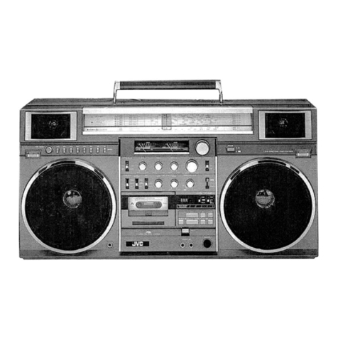
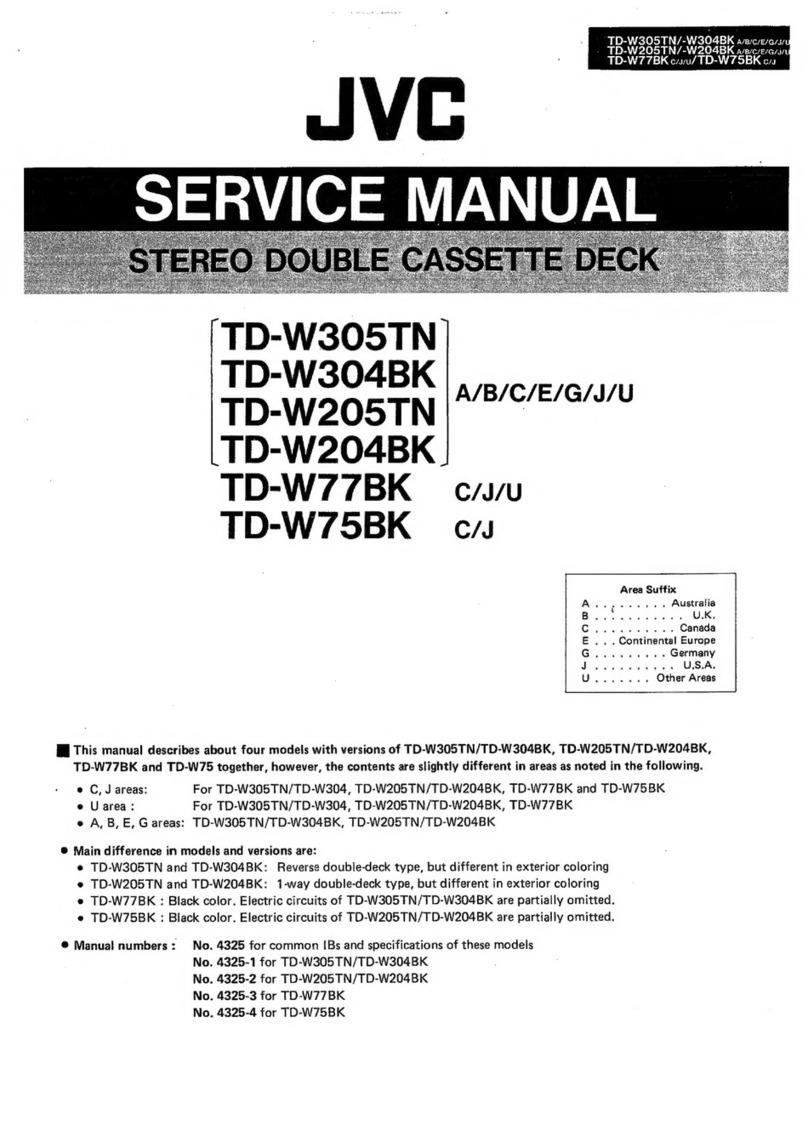
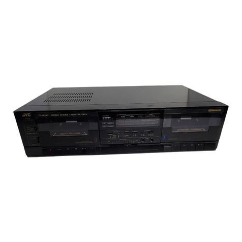
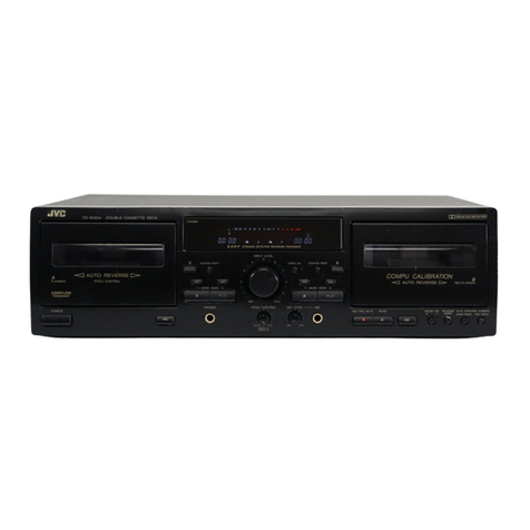
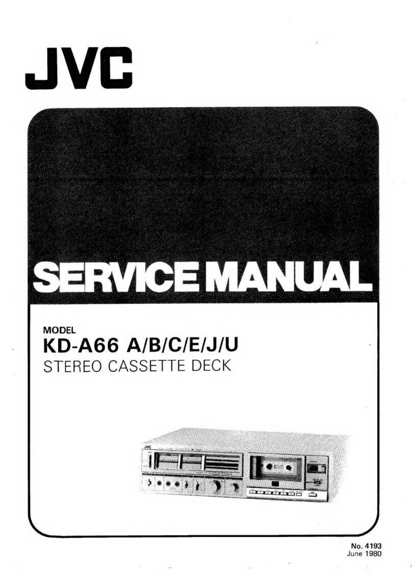
JVC CD-1920 User manual

MODEL
CD-1920/A/B/C/E/U
STEREO
CASSETTE
DECK
No.
4142
February
1976

Contents
Specifications..........
Features
.............-
Controls
and
Connections
Main
Parts
Location
.....
New
Technique
........
Main
Parts
Removing
....
Enclosure
Assembly
...
Electrical
Parts.......
Mechanical
Parts
Adjustments...........
Electrical
Adjustment
Mechanical
Adjustment
Specifications
Type
Track
system
Cassettes
Frequency
response
S/N
Wow
and
flutter
Crosstalk
Harmonic
distortion
Bias
Erasure
Heads
Motor
Tape
speed
Recording
time
Fast
forward
time
Rewind
time
Semiconductors
CD-1920/A/B/C/E/U
No.
4142
Stereo
cassette
deck
4-track,
2-channel
C-30,
C-60,
C-90
20
—
18,000Hz
(30
—
16,000Hz
+3dB)
with
chrome
tape
20
—
17,000Hz
(40
—
15,000Hz
+3dB)
with
normal
tape
52dB
(from
peak
level)
The
S/N
is
improved
by
5dB
at
1kHz
and
by
10dB
above
5kHz
with
ANRS
on.
0.09%
(WRMS)
65dB
1.3%
(normal
tape)
AC
bias
(95kHz)
AC
erasure
2
heads
Hard
permalloy
head
for
recording/playback
and
ferrite
head
for
erasure
Electronically
governed
DC
motor
4.8cm/sec.
2
x
30
minutes
with
C-60
cassette
125
sec.,
with
C-60
cassette
125
sec.,
with
C-60
cassette
7
ICs,
26
transistors,
2
SCRs
and
42
diodes
Input
jacks
Output
jacks
DIN
connector
(REC/PB)
:
Power
requirement
Power
consumption
Dimensions
Weight
Page
Page
aed
Peale
eee
eee
2
Trouble
Shooting
Guide
............-+--0--00-.
8
(kA
eRe
es
3
Maintenance::.c260.ccseweiatbaavtiecvediew
scene
9
B
Shani
te
ale
iiaegue
ters
whataueanteyen
OG
3
WHING
ceric
Scene
Cadmarannkemacccasmereaeaie
10
bop
wh
Fie
Baal
wie
Af
auegae
sarees
4
Standard
Schematic
Diagram
..........----.-+-+.
12
s-Gtiavo
this
eee
a
le
Bee
ees
4
Block
Diagram
.........00
cece
cece
e
eee
ee
eeeeee
WS
dhaf ais:
GrGkshererenenare
ve
<arapensimule
ane
5
Circuit
Board
Parts...........-0-2002
ee
eee
ee
eeee
14
erate
e
aaa
awe
ee
5
Mechanical
Components
..........200+eeeeeeeee
23
ine
EMa
Miao
Rates
ws
5
Enclosure
Assembly
and
Electrical
Parts
sales
eee
AHS
Rw
Ears
6
Except
Circuit
Board
Parts
.........--0+.000++
27
Ba
ied
woe
ume
atsens
eceyiacis
vases
merce
7
Packing)
sities
can
ciocrtareecieeenssesasoae
cine
28
iGteacsde
Gite
Gare
were
naar
7
ACCESSOFICS
«i
ccc
eee
nam
eee
caaceon
28
(OStaPeetswsiGuvecesen
8
Mic
jack
x2
Max.
sensitivity
0.2mV
matching
impedance
6002
—
10k2
Input
jack
x2
Min.
input
level
80mV
Input
impedance
100k2
Output
jack
x
2
Output
level
0.3V
Output
impedance
5kQ
Matching
load
impedance
50kQ
or
more
Headphone
jack
x
1
Output
level
0.3mW
Matching
impedance
82
—
1ka
Min.
input
level
15mV
Input
impedance
10ka
Output
level
0.5V
Output
impedance
5ka
Matching
impedance
50kQ
or
more
AC
120V,
60Hz
(CD-1920/C)
AC
240V,
50Hz
(CD-1920A/B)
AC
100V,120V,220V,
50Hz
(CD-1920E)
AC
100V,120V
,200V
,220V
50/60Hz
(CD-1920U)
30W
Width;
15-3/8""
(390mm)
Height;
5-15/16”
(151mm)
Depth;
12-5/8"
(321mm)
15.8
Ibs.
(7.2kg)
Design
and
specifications
are
subject
to
change
without
notice.

Features
“N/ertical-open-view”’
cassette
deck
Multi-point
peak
level
indicators
ANRS
Integrated
Circuit
ID
(Independent
Drive)
mechanism
Full
auto
stop
Air-damped
cassette
door
(Pat.
pending)
Input
select
switch
Tape
select
switches
Controls
and
Connections
Oo
®
8
®©
G8
&©®D
B®
YD ®@
®W
®
®
Fig.
1
WARNING
When
oot
in
use
‘or
fomaving
covers’
sh
from
mains
by
withdrawing
wall
plug.
Fig.
2
1
Headphone
jack
(PHONES)
16
REC-LEVEL
controls
2
Right
channel
microphone
jack
(MIC-R)
17
Rewind
button
(REW)
3
Left
channel
microphone
jack
(MIC-L)
18
Record
button
(REC)
4
Left
channel
level
meter
19
Play
button
(PLAY/REC)
5
PEAK
level
indicators
20
Fast
forward
button
(FF)
6
Right
channel
level
meter
21
STOP/Eject
button
(STOP/EJECT)
7
REC
indicator
22
Pause
button
(PAUSE)
8
ANRS
indicator
23
POWER
switch
9
Cassette
door
24
Left
channel
LINE
IN
terminal
10
Tape
COUNTER
25
Right
channel
LINE
IN
terminal
11
Counter
reset
button
26
Left
channel
LINE
OUT
terminal
12
INPUT
SELECT
switch
27
Right
channel
LINE
OUT
terminal
13
ANRS
switch
28
DIN
socket
(REC/PB)
14
TAPE
SELECT
EO
switch
29
Power
cord
15
TAPE
SELECT
BIAS
switch
CD-1920/A/B/C/E/U
No.
4142

Main
Parts
Location
©
®
Fig.
3
New
Technique
The
multi-point
peak
level
indicators
let
you
know
the
precise
levels
of
the
peak
signal
pulses
that
the
mechanical
VU
meters
cannot
follow.
They
are
essential
aids
for
making
good
recordings,
for
they
allow
recording
at
maximum
levels
without
exceeding
the
magnetic
saturation
level
of
the
tape.
During
adjustment,
sine
waves
are
used
and
the
indication
of
the
VU
meters
corresponds
to
that
of
the
peak
level
indicators.
But,
for
ordinary
musical
signals,
the
VU
meters
usually
indicate
lower
values
because
of
their
slower
response.
oro
na
a
=
=
=
O
!
L-CH
!
Power
supply
Input
H
.
|
terminal
terminal
I
re
Da404aP
I
Vcc=5V
R-ch
H
“
x
Light
Emitting
{
Input
I
Diode
(LED)
!
terminal
Mecsas
es
Se
es
Se
4
Fig.
4
CD-1920/A/B/C/E/U
No.
4142
MIC
jack
circuit
board
Main
amp
circuit
board
Peak
level
circuit
board
DIN
jack
PIN
jacks
ANRS
circuit
board
Power
transformer
Power
supply
circuit
board
Motor
ass’y
Cds
lamp
Flywheel
ass’y
Head
wire
terminal
circuit
board
Air-damp
pipe
Level
meter
(Right)
Indicator
circuit
board
Level
meter
(Left)
OONOoORWN
=
The
left
and
right
channel
inputs
are
individually
rectified
and
the
capacitor
C
is
charged
by
the
higher
of
the
left
and
right
channel
signal
levels.
The
variable
resistor
VR
adjusts
the
lighting
level
of
the
LED.
When
no
input
signal
is
available,
the
transistor
X
is
conducting
because
base
current
is
applied
through
the
resistance.
At
this
time
the
output
terminal
of
the
IC
TD3404AP
is
at
a
high
level
(5V),
providing
no
current
to
the
LED,
which
does
not
light
up.
When
the
base
potential
of
the
transistor
X
is
reduced
to
below
0.6V
by
the
input
signal,
X
becomes
non-conducting,
the
IC
output
is
at
a
low
level
(OV)
and
current
flows
to
the
LED
and
lights
it
up.
The
multi-point
peak
level
indicators
consist
of
five
of
the
circuits
encircled
by
the
broken
line,
connected
in
parallel.
Each
of
the
VRs
is
adjusted
according
to
the
signal
level
at
which
the
LED
lights
up
to
indicate.
A
circuit
which,
with
high
level
inputs,
provides
low
level
outputs
and
vice
versa,
such
as
TD3404AP,
is
usually
called
an
inverter.
This
1C
TD3404AP,
widely
used
in
computers,
is
a
digital
|C
which
includes
six
such
inverter
circuits,
five
of
which
are
used
in
this
set.
For
easy
use,
the
peak
level
indicator
circuit
of
this
set
is
so
designed
that
the
higher
one
of
the
right
and
left
channel
signal
levels
is
detected
to
light
the
LED.
The
attack
time
is
established
at
about
4msec,
achieving
both
easy
visibility
and
indication
accuracy.
For
adjustment,
see
the
section
‘“ADJUSTMENTS”
on
page
rp

Main
Parts
Removing
This
cassette
deck
which
features
a
compact
design
and
high
performance
uses
minuature-sized
parts
which
are
closely
arranged.
Use
special
care
when
servicing
it.
Enclosure
Assembly
Steel
cover
REC-LEVEL
Bottom
cover
knobs
Fig.
5
REC
LEVEL
Pull
off
the
inner
knob
and
the
outer
ring
@)
control
knobs
to
front
side.
Cassette
door
1.
Press
the
EJECT
button
to
open
the
GB)
cassette
door.
Inner
knob
—
for
left
channel
Outer
ring
—
for
right
channel
e
When
the
cassette
door
be
removed,
can
easy
clean
or
demagnetize
the
head.
e
When
replace
the
cassette
door,
insert
it
that
ball
bearings
be
full
locked.
.
Remove
the
cassette
door
by
sliding
it
upward.
Remove
2
screws
and
washers
of
both
sides
(L
&
R).
Steel
cover
Almost
all
parts
of
circuit
board
can
be
checked
when
only
steel
cover
is
removed.
Bottom
cover
e
3¢
8mm
screws
e
Almost
all
pattern
side
of
circuit
board
can
be
checked
when
only
bottom
cover
is
removed.
Remove
6
screws
and
6
washers
fastening
the
bottom
cover.
Front
panel
.
Remove
3
tapping
screws
fastening
up
side
of
the
F.
panel.
.
Remove
2
tapping
screws
fastening
under
side
of
the
F.
panel.
Remove
the
front
panel
after
removing
the
steel
cover
and
bottom
cover.
Remove
meter
escution
after
removing
the
front
panel.
Meter
escution
Remove
2
screws
(L
and
R
side
of
up-
ward)
fastening
the
meter
escution.
Rear
cover
.
Remove
3
screws
fastening
the
bottom
cover.
.
Remove
2
screws
(L
and
R
side
of
under
side)
fastening
the
rear
cover.
@
®
®
©
@
©
Electrical
Parts
Main
amp
C.
board
Fig.
6
Main
amp
circuit
board
Remove
the
main
amp
circuit
board
after
removing
the
front
pan
1.
Remove
2
screws
fastening
the
switch
ass’y.
.
Remove
rod
of
the
recording
lever.
.
Remove
4
tapping
screws
fastening
the
main
amp
circuit
board.
REC
volume
Remove
washer
and
nut
of
the
V.
Resistor
shaft
fastening
the
front
bracket.
Peak
level
Remove
4
tapping
screws
fastening
the
C.
board
peak
level
C.
board.
Power
supply
Remove
4
tapping
screws
fastening
the
C.
board
power
supply
C.
board.
ANRS
C.
board
Remove
4
tapping
screws
fastening
the
power
ANRS
C.
board.
Power
transformer
Remove
2
screws
and
washers
fastening
the
power
transformer.
MIC
jack
ass’y
Remove
2
screws
fastening
the
MIC
jack
ass’y.
Remove
the
V.
Resistor
after
removing
the
front
panel.
The
left
side
of
front
bracket.
CD-1920/A/B/C/E/U
No.
4142

Mechanical
Parts
Cassette
holder
Removing
the
cassette
holder
Don’t
remove
this
case
froin.
mecha
chassis
Remove
only
the
motor
Mecha
chassis
Cassette
Motor
speed
adjustment
holl
Flywheel
holder
®
Front
bracket
.
@
Nylon
washer
Fig.
7
CD-1920/A/B/C/E/U
No.
4142
Remarks
.
Press
the
EJECT
button,
then
the
cassette
door
be
loaded
Remove
the
brake
arm
(1)
from
stud
of
cassette
holder.
.
Remove
a
screw
@
fastening
the
recording
arm.
.
Remove
4
screws
fastening
the
front
bracket.
.
Pull
off
the
mecha-ass’y
to
back
side.
Cassette
holder
.
Remove
a
screw
fastening
the
cassette
holder.
.
Remove
“E”
ring
holding
the
brake
arm.
.
Remove
“E”
ring
holding
the
shaft.
.
Pull
off
the
shaft
to
right
side.
.
Remove
the
cassette
holder
by
sliding
it
upward
on
A
position
of
panel
bracket.
Don’t
remove
the
motor
case
from
mecha
chassis
and
remove
the
motor
only,
you
can
be
easy
replaced
it.
1.
Remove
the
take
up
belt.
2.
Remove
the
capstan
belt.
3.
Disconnect
2
wires
of
motor.
4.
Remove
a
screw
fastening
the
bottom
plate
of
motor.
.
Remove
a
screw
fastening
the
transistor.
.
Press
the
motor
from
upward
(pully
side),
then
can
be
removed
the
motor.
Flywheel
.
Remove
2
screws
fastening
the
muting
SW
bracket.
.
Remove
the
capstan
belt.
.
Remove
4
screws
fastening
the
flywheel
holder.
.
Pull
off
the
flywheel.
Pinch
roller
arm
ass’y
.
Remove
“E”
ring
holding
the
pinch
roller
arm
ass’y.
.
Remove
spring
on
the
arm
ass’y.
.
Remove
2
screws
fastening
the
cassette
holder.
.
Remove
the
counter
belt.
.
Remove
“E”
ring
holding
the
take
up
disc.
.
Pull
off
the
disc
from
the
shaft.
Take
up
disc
.
Remove
the
cassette
holder.
.
Remove
“E”
ring
holding
the
supply
disc.
.
Pull
off
the
disc
from
the
shaft.
Supply
disc
NOTE:
1.
Don’t
dirty,
slippery
and
undue
run-out
the
capstan
belt
and
counter
belt.
When
the
brake
arm
remove,
be
carful
not
to
stain
the
‘‘O”
ring
and
don’t
less
grease.
When
replace
the
cassette
holder,
don’t
forget
2
washers
of
the
shaft.
Be
carful
not
to
stain
the
belt.
Be
carful
no
to
stain
the
belt.
When
replace
the
flywheel,
don’t
forget
to
insert
a
nylon
washer
to
it’s
shaft.
2.
Adjust
height
of
the
motor
pulley,
when
the
capstan
belt
connect
to
the
flywheel
from
the
motor,
pulley,
so
that
it
will
be
parallel
to
the
chassis.

Adjustments
Electrical
Adjustment
Equipment
and
measuring
instruments
used
for
adjustment.
1.
V.T.V.M.
(measuring
AC
in
millivolt)
2.
Audio-frequency
oscillator
(range:
50—20kHz
and
output
OdB
with
impedance
6002
)
3.
Attenuator
4.
Reference
tapes
for
REC/PB
TS-1
(QP-12,
C521V)
—
normal
tape
TS-2
(TP-18,
C401R)
—
chrome
tape
5.
Reference
tapes
for
playback
VTT-664
(1kHz
16mM)
VTT-666
(400Hz
22mM)
6.
Resistors
1002
(for
measurement
of
the
bias
current)
AUDIO
Freq.
OSC
6002
(for
attenuator
matching)
Fig.
8
.
Set
the
deck
in
the
record
mode,
and
set
INPUT
SELECT
switch
at
LINE
IN.
2.
Input
1kHz
signals
(about
10dBs)
from
LINE
IN
jacks
and
adjust
volume
control
so
that
test
points
and
are
-3dBs.
3.
Adjust
semi-fixed
resistors
VR103
and
203
in
this
condition
it
obtain
zero
VU
meter
reading.
Peak
level
1.
Set
as
same
mode
at
step(1)
and
(Peak
level
adjust
semi-fixed
resistor
VR703
so
C.
board
that
the
0”
indicator
is
lighting
and
TAA305306)
no
lighting
at
-1dB
from
step(1)
with
VR703
attenuator.
2.
Adjust
semi-fixed
resistor
VR704
so
VR704
that
the
‘’-5”
indicator
is
lighting
at
-5dB
from
step(1)
with
attenuator.
3.
Adjust
semi-fixed
resistor
VR705
so
VR705
that
the
‘’-10”
indicator
is
lighting
at
-10dB
from
step(1)
with
attenuator
and
no
lighting
at
-11dB
from
step(1)
with
attenuator.
4.
Adjust
semi-fixed
resistor
VR702
so
that
the
“+3”
indicator
is
lighting
at
+3dB
from
step(1)
and
no
lighting
at
+2dB
from
step(1)
with
attenuator.
5.
Adjust
semi-fixed
resistor
VR701
so
that
the
+6”
indicator
is
lighting
at
+5dB
from
step(1)
with
attenuator.
1.
Level
meter
deflection
(Main
amp
C.
board
TAA305204)
The
angle
of
meter
deflec-
tion
has
been
factory-
adjusted,
but
should
be
adjusted
when
parts
are
replaced.
VR103,203
When
adjust
the
level
meter,
don’t
use
a
headphone.
Playback
1.
Set
equalizer
switch
at
normal
and
(Main
amp
1.
Adjust
playback
sensi-
sensitivity
playback
reference
tape
VTT-664.
C.
board
tivity
when
heads
are
Adjust
semi-fixed
resistors
VR101(L)
VR101,201
replaced.
and
VR201(R)
so
that
test
points
and
are
—3dBs,
then
level
meters
indicate
zero
VU
(about
0.3V
at
LINE
OUT).
2.
Playback
reference
tape
VTT-666
and
check
that
the
VU
meter
indicate
CAL.
2.
Make
this
adjustment
after
making
sure
level
meter
deflection
angle
is
correct.
No.
Item
4.
|
Bias
current
Recording
signal
current
ANRS
circuit
(DC
bias)
.
Set the
deck
in
the
record
mode.
.
Input
the
1kHz
signals
to
LINE
IN
Procedure
.
Insert
a
1009
resistor
into
the
ground
side
wiring
of
the
head
and
connect
the
V.T.V.M.
across
the
resistor,
and
set
the
BIAS
SW
at
chrome
or
normal.
Set the
deck
in
record
mode.
Input
signals
to
LINE
IN
jacks
and
adjust
the
recording
level
control
so
that
the
test
points
and
are
-13dBs.
First
adjust
for
chrome
tape,
then
for
normal
tape.
.
After
the
deck
correct
the
head
wires,
input
the
standard
level
of
1kHz
sig-
nals
to
use
reference
tape,
and
measu-
re
REC/PB
frequency
response
at
10kHz.
.
Adjust
semi-fixed
resistors
VR502,504
(chrome)
501,
503(normal)
so
that
the
10kHz
frequency
response
does
become
+10dBs
Repeat
the
recording
and
playback
so
that
10kHz
signals
become
correct
fre-
quency
response.
Level
over
at
10kKHz
compared
with
1kHz
—
bias
current
less
Level
less
at
1OkKHz
compared
with
1kHz
—
bias
current
over
jacks
and
adjust
the
recording
level
control
so
that
the
test
points
and
are
-13dBs,
make
recording
in
such
a
way.
.
Adjust
the
semi-fixed
resistors
VR104,
204
(chrome),
VR105,205(normal)
so
that
the
test
points
are
-13dBs.
.
Disconnect
+B
of
bias
circuit
so
that
oscillator
does
not
operate.
(Desolder
the
BIAS
CUT
in
main
amp
circuit
board)
.
Set the
deck
in
the
record
mode.
.
Apply
signal
of
1kHz
to
LINE
IN
and
adjust
volume
control
so
that
test
points
[12]
and
[62]
(in
main
amp
circuit
board)
are
OdBs.
.
Then,
connect
the
V.T.V.M.
to
test
points
(h)
G)
in
main
amp
circuit
board
and
adjust
below
steps.
.
Apply
signal
of
1kKHz,
—40dB
to
LINE
IN
and
adjust
R401,401
so
that
LINE
OUT
is
-34.3dB
with
ANRS
ON.
.
Apply
signal
of
5kHz
+40dBs
to
LINE
IN
and
adjust
R302,402
so
that
LINE
OUT
is
-17.5dBs
with
ANRS
ON.
.
When
apply
signal
of
1kHz
to
LINE
IN
and
output
is
OdB,
adjust
steps
(5)
through
(6)
so
that
level
does
not
change
when
ANRS
is
turned
on
and
off
(£5dB
less).
.
Playback
reference
tape
VTT-664
and
check
LINE
OUT
level
so
that
it’s
compare
are
+1dB
less
with
ANRS
SW
on
to
off.
.
Connect
+B
of
bias
circuit
(Solder
the
printed
in
main
amp
circuit
board
for
connect
+B).
(re
|
Ree
[Remar
1.
Adjust
bias
current
when
heads
or
other
parts
are
replaced.
2.
Use
the
highclass
V.T.V.M.
for
high
frequency
re-
sponse.
3.
After
the
bias
current
adjustment,
check
the
fre-
quency
response
at
10kHz
signals.
chrome
VR502,504
normal
VR501,503
(Main
amp
C.
board)
.
This
adjustment
is
necessa-
ry
when
heads
are
replaced.
2.
Make
this
adjustment
after
adjusting
steps
(1)
through
(4).
3.
Check
the
frequency
re-
chrome
sponse
at
10kHz
after
this
VR104,204
adjustment.
normal
4.
Set
EO
and
BIAS
switches
VR105,205
according
to
type
of
tape
used,
1.
See
figure
of
ANRS
circuit.
2.
Repeat
steps
(5)
through
(6).
Step
(5)
is
5.7dB
up.
Step
(6)
is
2.5dB
up.
CD-1920/A/B/C/E/U
No.
4142

Mechanical
Adjustment
1.
Replacement
and
adjustment
of
the
head
2.
(See
@
®@
©
O
in
Fig.
7
of
page
6)
If
either
of
the
record/playback
head
and
the
erase
head
shown
low
performance
because
of
wear,
broken
wire
or
excessive
magnetization,
it
should
be
replaced.
Screws
to
be
removed
REC/PB
head
E
head
REC/PB
head
After
replacement,
adjust
the
head
for
azimuth.
1.
Insert
the
cord
plug
into
the
LINE
OUT
jack
(or
REC/PB),
and
connect
the
other
end
of
the
cord
to
a
V.T.V.M.
(vacuum
tube
voltmeter).
2.
Play
the
azimuth
adjustment
test
tape
(e.g.
JVC’s
VTT-653,
10kHz).
3.
Turn
the
azimuth
screw
so
that
the
output
will
become
maximum.
If
the
azimuth
adjustment
test
tape
is
not
available,
play
a
music
cassette.
When
treble
response
becomes
optimum,
set
the
adjustment
screw
(@).
4.
After
this
adjustment,
the
screw
@)
should
be
locked
with
a
bond.
If
necessary,
adjust
playback
sensitivity,
current,
REC
signal
current
and
bias
trap.
REC
_
bias
Erasing
head
After
replacement,
adjust
the
head
for
height
position.
1.
Play
the
test
tape
(C-120).
2.
Turn
the
adjustment
screw
©
so
that
the
test
tape
move
running
to
no
touch
the
tape
guide
tip
(up
or
under
side).
If
checking
is
difficult,
cut
front
upper
side
of
the
cassette
of
C-120
by
a
cutter
knife,
etc.,
then
can
easy
check
it.
REC/PB
HEAD
Adjusting
the
motor
speed
1)
Play
back
reference
tape
(3000Hz),
and
adjust
the
semi-VR
in
the
motor
that
it’s
speed
in
3000Hz+2%
(2970Hz~
3060Hz).
2)
CD-1920
need
not
to
change
cycle,
whether
the
commercial
frequency
in
your
area
is
50
or
60Hz.
CD-1920/A/B/C/E/U
No.
4142
Trouble
Shooting
Guide
[ELECTRICAL
CIRCUIT]
1.
Playback
tone
quality
is
poor.
1.
Check
the
record/playback
head
for
dust.
2.
Check
the
record/playback
head
for
wear.
If
worn
excessively,
the
loss
of
treble
response
will
result.
3.
Check
wiring
for
a
short-circuit.
Check
each
transistor
for
condition.
2.
Recording
tone
quality
is
poor.
The
playback
tone
quality
of
a
recorded
tape
such
as
the
audition
tape
is
good,
but
the
recording
by
this
unit
produces
poor
tone
quality.
In
this
case,
the
unit
should
be
checked
in
the
following
manner.
‘
1.
By
monitoring
a
music
while
recording,
check
the
tone
quality.
|
2.
If
found
poor,
check
the
wiring
of
the
recording
system
for
a
broken
wire
and
short-circuit.
3.
If
no
irregularity
is
found,
check
the
recording
bias
current.
Also
check
the
oscillation
circuit.
3.
For
other
failures,
check
the
unit
in
the
same
manner
as
other
amplifiers.
a
a
3.
Standard
torque
70
gr-cm
or
more
70
gr-cm
or
more
35~
70
gr-cm
Fast
forward
torque
Rewinding
torque
Take-up
torque
4.
Door
opening
speed
adjustment
(See
in
Fig.
7
of
page
6)
Door
opening
is
opened
slowly
by
screw
E
is
loosened
and
move
the
bracket
position
to
back
side.
(The
spring
tension
varies
strong)
[MECHANISM
SECTION]
(wow
and
flutter)
If
wow
and
flutter
increase,
check
the
following
points.
If
there
is
defect
in
revolving
parts,
the
wow
and
flutter
generated
will
increase
in
proportion
to
the
number
of
revolutions.
es
Capstan
and
flywheel
Pinch
roller
Take-up
idler
arm
[MECHANICAL
REPAIRS]
Take-up
idler
arm
Standard
take-up
torque
not
available.
Play
a
3000Hz
test
tape,
and
defective
part
can
be
detected
from
the
sound.
Capstan
shaft
has
excessive
run-out.
Flywheel
turns
heavily.
(shaft
seisure,
thrust
play,
etc.)
Replace
flywheel.
Adjust
plastic
screw
with
flywheel
holder.
Clean
the
capstan
shaft
and
the
groove
in
the
flywheel.
Apply
oil
to
the
metal
position.
Replace
the
capstan
assembly.
Rough
rotation
(Deformation
scratches,
or
dust).
The
angular
position
of
the
pinch
roller
is
not
correct.
The
pinch
roller
pressure
is
not
correct.
Replace
pinch
roller.
Clean
the
pinch
roller
or
apply
oil
to
the
rotary
shaft.
Adjust
the
pinch
roller
so
that
it-is
parallel
with
the
capstan
shaft.
Adjust
the
pinch
roller
spring.
Clean
the
belt
or
remove
the
distortion.
Replace
the
belt.
Belt
has
undue
run-out.
;
Belt
is
dirty
or
slippery.
Back
tension
is
irregular,
or
back
tension
is
too
strong.
Replace
supply
disc.
Replace
back
tension
spring
(under
supply
disc),
or
apply
silicon
grease.
Motor
shaft
has
undue
run-out.
Motor
pulley
is
oily
and
dusty.
Replace
motor.
Clean
motor
pulley.
Pulley
has
deflection.
Pulley
is
stuck.
Replace
take-up
idler
arm.
Replace
take-up
idler
arm.
Replace
take-up
idler
arm
pressure
spring.
Clean
or
replace
capstan
belt.
Clean
rubber
rim
of
the
right
reel.
Reel
disc
and
idler
Fast-forward
torque
not
available.
Clean
rubber
rim
of
the
right
reel
or
replace
reel
disc
assembly.
Clean
or
replace
fast-forward
idler.
Clean
rubber
rim
of
the
left
reel
or
repalce
reel
disc
assembly.
Clean
rewind
idler
tire.
Door
brake
Door
does
not
open
fully.
Apply
a
small
quantity
of
silicon
grease
to
the
inside
surface
of
the
brake
pipe.
(SHIN
ETSU
KAGAKU
KS-64
or
equivalent)
Braking
not
sufficient.
Replace
brake
pipe
or
rubber
O-ring.
Check
slide
lever
and
solenoid
iron
core
for
smooth
movement.
Check
if
the
locking
and
sliding
parts
of
the
operation
button
cam
are
well
coated
with
molybdenum.
Auto-stop
mechanism
Auto-stop
not
operating.

Maintenance
To
get
long,
trouble-free
service,
maintenance
is
important.
2.
Pinch
roller
and
capstan
Do
not
forget
cleaning
and
demagnetizing.
1)
Press
the
EJECT
button
with
the
POWER
switch
ON
to
open
the
cassette
door.
Cleaning
2)
Press
the
PLAY
button,
and
the
pinch
roller
will
After
long
use,
the
heads
and
tape
part
—
capstan,
pinch
move
out
and
rotate.
roller,
etc.
—
will
become
dirty
with
dust
or
magnetic
3)
Apply
a
soft
cloth
(soaked
in
alcohol,
it
will
be
more
particles.
Dirty
heads
cause
imperfect
erasing
or
high
effective)
to
the
rotating
pinch
roller
and
capstan.
frequency
drop-off.
A
dirty
capstan
and
pinch
roller
will
Be
careful
not
to
let
the
cloth
get
caught!
cause
unstable
tape
speed,
leading
to
increased
wow
and
*
Do
not
use
any
cleaner
besides
alcohol
or
a
flutter.
specifically
prepared
tape
head
cleaning
solution.
Always
keep
them
clean
by
following
the
procedure
below.
1.
Heads
1)
Press
the
EJECT
button
with
the
POWER
switch
OFF
to
open
the
cassette
door.
a
2)
Remove
the
cassette
door
by
sliding
it
upward.
a
fo
—~
ra
Soft
cloth
—-
a
Direction
of
rotation
Nj
f
pinch
roll
Pinch
roller
N
ih
ile
Capstan
i
oy,
d
Fig.
10
Fig.
12
3.
Cabinet
When
the
cabinet
becomes
dirty,
wipe
it
with.
a
soft
3)
Press
the
PLAY
button
to
move
the
heads
out.
cloth
soaked
with
a
neutral
cleaning
solution
of
a
4)
Use
the
head
cleaning
stick
provided
to
wipe
the
polishing
cloth.
surface
where
the
tape
comes
into
contact
with
the
*
Do
not
use
thinner
or
benzine.
head.
(It
is
effective
to
moisten
the
cotton
with
alcohol.)
Demagnetizing
The
heads
are
made
from
a
material
resistant
to
magnetization,
but
after
long
use
they
may
become
magnetized.
A
magnet
brought
into
their
vicinity
can
magnetize
the
heads,
causing
excess
noise.
If
noise
seems
to
have
increased,
demagnetize
the
heads
with
a
head
demagnetizer
through
the
following
procedure.
1.
Turn
the
POWER
switch
OFF.
2.
Wrap
the
tip
of
the
demagnetizer
with
vinyl
tape
or
soft
cloth
so
as
not
to
damage
the
head
surface.
Switch
on
the
demagnetizer
and
bring
it
close
to
the
head.
3.
Move
the
tip
of
the
demagnetizer
slowly
first
to
the
left
and
right,
then
up
and
down
in
front
of
the
head.
Gradually
move
it
away
from
the
head
and
switch
it
off
at
a
distance
of
more
than
30cm.
(12’’)
4.
The
erase
head
need
not
be
demagnetized.
The
capstan
shaft
and
tape
guide
should
be
demagnetized
in
the
same
way
as
the
record/playback
head.
*
Do
not
bring
a
magnetized
metallic
object
(a
.
screwdriver,
for
example)
near
the
head
as
this
will
Fig.
11
increase
noise.
CD-1920/A/B/C/E/U
No.
4142

Wiring
CD-1920A/B
CD-1920E
Select
switch
CD-1920U
Fig.
13
CD-1920/A/B/C/E/U
No.
4142
-

CD-1920/C
y
Earth
Lug
Headphone
Jack
MIC
Jack
C.
Board
DIN
Jack
PIN
Jack
ANRS
C.
Board
Power
Transformer
Indicator
C.
Board
Main
Power
Supply
C.
Board
Power
Switch
Head
Wires
i
Terminal
Muting
i
°C.
Board
Switch
Motor
Colour
code
are
shown
below
OD
hese
Brown
peter
Red
Pause
Switch
Bs
seeweee
ae
@®
sarchiwt
Yellow
©
orived
Green
©
wean
lae
Blue
eT:
A
eC;
)
See
Grey
$
¢
amp
Ho
eff
a
)
wees
White
L
R
=
Black
Fig.
14
CD-1920/A/B/C/E/U
-
No.
4142

Standard
Schematic
Diagram
Input
Level
Adj.
LEVEL
METER
CD-1920/C
POWER
TRANS
TAP
322201]
-0]
INPUT
Soea
+)
TOM265311-
05
HEAD
vO
_
re
c
xiol
x10z@
SELECT
Sw
Icio
x103
X10g
X106
x05
X501
A—o——_
and
2SA72ITU
28C1327TU
TATIaoP-B
2SC82BARS
2SCI384RS
2SC8ZBRS
2SC8ZBARS
2SC828ARS
PHONE!
ros
aro
SS
re
a
Baron
X@01
2SA564ARS
i
L-CH LINE
IN
|
aise.
SSK
PLAYZIV
&TOP
Z0.;
bist
ine
re
sige
Rata
-
a)
R-CH
LINE
IN
ihe
td
+
fe
3
ppt
Riat
cs
a
tee
tae
ss
=
av
R-CH
LINE
OUT
Cred)
grey
,
tegae
|
Brox
»
neg,
gon
6
OTST
|
L501
|
Scores
3225)
X90I/
|
90a
dy
TQ
CSF
s
|
Sy
eee)
|
eum
sore
Les
esos
SIE
lh
|
a
Ge
fe
or,
a
|
BEES
OM,
SE
ES
|
“ite
|
[|
hose
3
y
x50
We
||!
°
|
3
ait
=
(0)
I
|
Ks
3
ess
Coy
1
70
E.HEAD
|
3
4
34
4
>
in
Le
g
ie
g
.
a
rn
ra
2
g
S
(7)
Roz
|
6505
|
i.
ee
:
Cys
saiee
|
we
1g
é
106
|=
[x
KES
i
=
ey
a."
i
Hh
|
H
lg,
_|Sz0rr
3
|
\
=
a
|
2
|
pales
2
|
|
15K
ol
ra
199
Fe
Bishan
;
rN
aa
ie
|
£969
PeG.0
i
bbe
7
4
i
corn
Tey
i
‘S10l-z
‘$101-3
$/01-4
SWI-S
a
‘101-6
|
S10l-7
cag
g
‘c
REC/PB
SW
eX)
}
5104-1
(PB=~REC)
§|
S105*
R-
s103-1
BIAS
ri
H
EQUALIZER
SW.
4
Glas
|
Lisa
eeae|
||
POR
ee
eee
tttt*~é‘it~S*d
|
|
an
ree
|
Ea
Ce
a
oe
i
nn
i
a
Biss
Ad.
et
a
ae.
moicaron
R/P.
HEAD
jAnrs
INDICATOR
|
Reo!
!
R-CH
R-cH
Ee)
ar
ate
RO
Re
A
=
|
R/P.
HEAD
Gee
oe
SU
SSS
Sa
eee
ee
ee
rvs
G
0803)
+
640
en
@
1301
t
we
r
H
=;
RIOT
\Dg04d|
+
3A4B
ene
ng
a
ee
po
me
tp
ioone
TBF
R708
!
peos|
048
PEAK
LEVEL
=
ae
:
390
;
|
INDICATOR
HEAD
BOARD
:
Se
—@f@-9"|
-
5aB
TAA305426-O1
2
“0
re
|
Vid
|oB07
)-
1048
5
$9"
7
|
bee
7
Te
|
Gprasasaesor—
ka
—
|
X701~X705
1C701
Hl
2SC828S
TD3404AP
a
Jumping
Wire
L-CH
~
Capitat
Letter
(A,B,C)
Hofe
Number
R-CH
Sma
Letter
(@,b,C°)
(ea
i
ane
Peak
Level
Adj
Wiceoiae
on
D2
i
;
pping
Pin
Number
=
L-CH
ANRS
DC
Bias
Adj.
SOLENOID
R-CH
~
:
eae
J
SR
MITOLSTOP
METER
LAMP
L-CH
only
or
R-CH
only
~
S101-1-9,
201-1-9
REC/PB
SW.
AT
“PB”
MODE
Stel
QLPato1-
005
C.R
Used
Wo.
RION
~
151
20l
~
251
S102
202
INPUT
SELECT
SW.
AT
"LINE
IN”
POSITION
: .
301
~
3I5
aol
~
415
S82,
203-1
ANRS
SW.
AT
“ANRS
OFF”
POSITION
~
~
SI0G-1~3,
204-1~3
EQUALIZER
SW.
AT
“NORMAL”
POSITION
oi
~
ae
eo
si
$105-1,2,
205-1,2
BIAS
SW.
AT
“NORMAL”
POSITION
902
~
905
S106
MUTING
SW.
AT”
MUTING
ON~
MODE
x601
x602
Cloz2
~
136.
/91,
202
~
236,
291
sI
POWER
SW.
AT
“POWER
OFF“
25C828RS
2SCazeRs
POWER
TRANS
501
=
923.
90
©
923.
50!
~
507
sz
PAUSE
SW.
AT
“PAUSE
OFF~
eae
TAP32630/—
of
60!
~
614,
101,
69/
~
694
.
33
HOTOR
SW.
AT
“MOTOR
OFF”
—
ee
mane
CR
Lack.
No
R103,
203,
118,
218, 105,
245.
901.
614~620
peos
2607~D6I0
Q
CIOl,
201.
12@.
229,
132,
232,
106,
206,
611,806,607
sop)
x
4
Mc
a7a3
QMc
0306
LAMP
FOR
AUTO.
STOP
T4682!
-004
_C1
0.0224F
POWER
coRD
C400
/120/
200
/
220v
MS
fete
4
denn
[Power
SiPREY
Grea
Tanwne-o2
Jonge
1
PT
tt
|
aad
[POWER
SUPPLY
CIRCUIT
|
2
Neste
|
|.
oN
2
ol)
SS
ae
es
J
CD-1920/A/B/C/E/U
No.
4142
MUTING
SW
SZQ_
}
53
4
PAUSE
S¥
=
MOTOR
sw
Fig.
15
=4{2
=
cr
o.ozemr
alas
st
o4
POWER
SW
°
POWER
CORD
=
Ac
I2z0V
ena
POWER
TRANS
TAP32/30/~
Of
for
Mode
for
Model
CD-1920A
cd-
19208
Power
coRD
|
=|
PowER
CORD
|
|
/
o-oo
af
|
|
-
i
<i
CD-1920E
POWER
TRANS
TAP
31820)
-
of
VOLTAGE
SELECT
SW
51
54
n=
---
220
=
2+
120V
cor)
(00V
POWER
CORD
b
$0fbo
Hz
RED
tt
aul
FUSE,
2,9
for
Model
CO-/920U
AC
240Vv
$0
He

[Variable
resistors]
VR101,201
VR102,202
VR103,203
VR104,204
VR105,205
VR301,401
VR302,402
VR501
VR502
VR503
VR504
VR701,702,703,
704,705
VR901
[Switches]
$101-1~9,
201-1~9
$102,202
$103-12,203-1
$104-1~3,
204-1~3
$105-1,2,205-1,2
$106,206
$1
$2
$3
[Transistors]
X101,201
X102,202
X103,203
-
X105,205
X106,206
X501
X901
X902
X701~
705
X601,602
X603
X604
X605
SCR2
(X2)
Playback
gain
adj.
REC
volume
VU
meter
gain
adj.
REC
gain
adj.
(chrome)
"
(normal)
ANRS
DC
bias
adj.
ANRS
control
amp
gain
adj.
Left
bias
adj.
(normal)
”
(chrome)
Right
bias
adj.
(normal)
"
(chrome)
Peak
level
adj.
Input
level
adj.
(Lch
only)
REC/PB
switch
(at
‘‘Playback’’
mode)
Input
select
switch
(at
“LINE
IN’
mode)
ANRS
switch
(at
“ANRS
OFF”
mode)
Equalizer
switch
(at
‘‘Normal’’
mode)
Bias
switch
(at
‘‘Normal’’
mode)
Muting
switch
(at
‘‘Muting
on’’
mode)
Power
switch
(at
‘“OFF’’
mode)
Pause
switch
(at
‘“OFF’’
mode)
Motor
switch
(at
‘“OFF’’
mode)
2SA721TU
2SC1327TU
2SC828ARS
2SC828ARS
2SC828RS
2SC828RAS
2SA564ARS
2SC828RAS
2SC828S
-~Main
amp
C.
board
Peak
level
C.
board
2SC828RS
2SA564ARS
2SC828RS
2SC1162WTBC
2SF656
Power
supply
C.
board
.
[IC]
1¢101,201
TA7140P-B
Main
amp
C.
board
1C301
TAT000332-01
ANRS
C.
board
IC302
TA7140P-BC
1C701
TD3404AP
Peak
level
C.
board
[Diodes]
D101,102
OA90
|
Main
amp
D901
RD43EC
C.
board
D301,302
OA90
D303
MA-150
}
ANRS
C.
board
D701,702,703,
OA90
Peak
level
704
C.
board
D601,602
OA90
D603
MA-150
D604,605,606,
10D1
607,608,609,
Power
supply
610,611,612,
|
C.
board
613,614
|
D615
RD24E
D616
1N4733T
B
Base
Ca—
C
Collector
Transistor
E
Emitter
Thyristor
2SF656
K
Cathode
A
Anode
G
Gate
om
1234567
TA140P-BC
1615
14131211109
12345678
TAT000332-01
14131211109
8
IC
TD3404AP
1234567
Fig.
18
=
tS
Biock
Diagram
Recording
system
To
peak
level
circuit
Level
meter
LINE
IN
Input
level
adj
REC
volume
Input
select
HOM
©)
Meter
gain
adj.
Headphone
MIC
jack
REC/PB
socket
R-CH
MIC
IN
Equalizer
switch
O
RCH
L-CH
IN
IN
ANRS
control
amp
gain
adj.
10302
TA?140P-8C
ANRS
OC
bias
adj,
ANRS
circuit
Fig.
16
Playback
system
Playback
Head
Playback
gain
adj.
X104
1C101
a
TA7140P-B.
2SC1384RS
X103
2SCB2BARS.
2
REC/PB
socket
ik}
—_?
LINE
OUT
D
ANRS
switch
ANRS
control
amp
gain
adj.
10302
TA7140P-
BC
ANRS
DC
bias
adj.
ANRS
circuit
Fig.
17
To
peak
level
circuit
Meter
gain
adj.
Bias
OSC
circuit
Level
meter
Headphone
CD-1920/A/B/C/E/U
No.
4142

Circuit
Board
Parts
Main
Amp
Circuit
Board
Main
Amp
Circuit
Board
Parts
List
ONe
Ac
State)
a
7
=
s
£
=
=]
we
=
E
s
s
8
8
o
Ses
TAA305204-01
Circuit
Board
for
main
amp
1
d
a
=
2
2
8
s
255
R104,204
ORD141K-224
C.
Resistor
220k2
YW
2
$
ac
=
g
©
3
;
hain
R105,205
n
124
120ka
"
2
v0
=
a=
soseeffadelfewewressonrernnesessnsssserrewwwmnnnnenesse
my
R106,206
ra
-393
39
ka
”
2
H
a
R107,207
»
+154
150ka
0"
2
R108,208
”
-823
82ka
"
2
R110,210
”
221
2202
"
2
R111,211,126,226
»
403
10k2
"
4
R112,212
”
-101
1002
"
2
R113,213,131,231
»
422
1.2k2
"
4
.
R114,214
"153
15ka
"
2
@
=
R115,215,119,219
n
292
2.2ka
0"
4
ale
R116,216,151,251
»
472
4.7k2
"
4
3
ae
R117
»
683
68ka
"
1
o
s
ES
R120,220
»
271
2702
"
2
(fa
ir
=
o,9
5
$)8
R121,221
»
821
8202
"
2
ols
R122,222,123,223
»
«332
3.3k2
"
4
.
ES
R124,224,125,225
»
402
1k92
"
4
=
=
w
R127,227
n
274
270ka
"
2
s
R128,228
»
473
47kaQ
0"
2
3
R129,229,149,249
»
562
5.6ka
"
4
3
R130,230
»
-151
1502
"
2
£
R132,232
»
183
18kQ
"
2
R135,235
n
-421
1202
"
2
R136,236
»
470
472
"
2
e
R137
,237,148,248
»
272
2.7ka
"
4
Po
-
R138,238
»
-392
3.9ka
"
Z
=
©
R139,239
»
333
33ka
"
2
S
2
R140,240
n
274
270k2
0"
2
s
3
R141,241
»
332
3.3ka
"
2
0
>
R142,242
»
561
5602
"
2
3
R143,243
»
820
820
"
2
2
R144,244
»
223
22kaQ
"
2
=
R146
,246
”
-154
150ka
"
2
R147,247,501
n
563
56kQ
"
3
R905
»
220
222
1
"
-ORO
Jump
Wire
02
5
R109,209
ORD143K-274
C.
Resistor
270ka
YAW
2
-
R902
»
333
33ka
"
1
=
R903
»
223
22ka
"
1
=
R906
»
472
4.7k2
"
1
&
R150,250
QRD141K-153
15k2
"
2
a
5
R133,233,134,234
|
ORD121K-331
3302
VA}
4
8
—
C108,208
QEW41AA-107
100uF
10V
2
>
8
C103,203
QEW41CA-476
;
47
uF
16V
2
a
3s
C115,215
0”
-107
100u
F
"
2
E
C125,225
0"
-336
33uF
"
2
=)
C110,210
QEB41EM-106
(Low
leak)
10uF
25V
2
C114,214,117,217
OQEW41EA-106
10uF
0"
4
C111,211,124,224
”
A476
A7uF
0"
4
C119,219
"
-107
100uF
"
2
C120,220,123,223
"
-335
3.3uF
"
4
©12'1,2241,127,227,
0”
475
4.7uF
"
7
130,230,901
C122,222
”
-105
TuF
°
”
2
C129
,229
QEW41VA-107M
100uF
35V
2
C107
,207
QEB41EM-336
(Low
leak)
33yuF
25V
2
C113,213
”
475
4.7
uF
2
Fig.
19
CD-1920/A/B/C/E/U
No.
4142
a

Ref.
No.
Parts
No.
C126,226
QEB41HM-684M
C104,204
QEE41EM-475
C109,209
OFM41HK-153
C118,218,131,231
”
-102
C116,216
OFM41HJ-392
C128,228
OFM41HK-273
C134,234
"
-152
C102,202
QCS11HK-821
C105,205
”
471
C136,236
”
-390
C112,212,133,233
”
-221
C135,235
”
-151
VR101,201
QVP8A0B-024
VR103,203
013
VR105,205,
”
-054
104,204
VR901
"
-015
L101,201
TAC000324-06
L102,202
"
-07
L103,203
"
-01
D901
RD4.3EC
$101-1~9,S201-1~9
QSS9201-001
$102,202
OQSP0249-101
$103-1,2,
203-1
$104-1,3,
204-1,3
$105-1,2,
205-1,2
X101,201
2SA721T,U
X102,202
2SC1327T,U
X103,203,105,205
2SC828ARS
X104,204
2SC1384RS
D101,201,102,202
OA90
1C101,201
TA7140PB
X901
2SA564ARS
X106,206
2SC828RS
(OSC
Circuit)
L501
TAC294421-01
X501
2SC828ARS
R502
QRD146K-100
R503
”
-151
C501,503
QFM42AK-103
C502
"
-153
C504
OFS42BK-222
C506
507
OCS12HK-221
C505
OEW41EA-475
VR501,502,503,
OQVP8A0B-015
504
L502
TAC000324-03
E43727-002
Parts
Name
Remarks
E.
Capacitor
0.68uF
50V
Tantal
E.
Capacitor
4.7uF
25V
Mylar
Capacitor
0.015uF
50V
n
0.001uF
”
0.0039uF
”
"
0.027uF
”
”
0.0015uF
"
Fixed
Ceramic
Capacitor
820pF
”
470pF
"
39pF
”
220pF
"
150pF
V.
Resistor
20k2
(B)
ie
1ka
(B)
50ka
(B)
100ka
(B)
Inductor
680u
F
"
3.3mH
"
18mH
Zener
Diode
Slide
Switch
Push
Switch
Ass’y
Si.
Transistor
Ge.
Diode
Integrated
Circuit
Si.
Transistor
OSC
Coil
Si.
Transistor
C.
Resistor
102
YAW
"
1502
”
Mylar
Capacitor
0.01uF
100V
”
0.015uF
”
Polystyrol
Capacitor
0.0022uF
Fixed
Ceramic
Capacitor
220pF
E.
Capacitor
4.7
uF
25V
V.
Resistor
100kQ
(B)
Inductor
1mH
Tab
oe
se
BNUNNANNNNNNANMNND
PH
NANNN—
2
2
4
2
4
2
1
2
DS.
2S
AG
SS
at
Rea
es
a
cs
CD-1920/A/B/C/E/U
No.
4142

ANRS
Circuit
Board
€)
‘Ipe
seiq
od
SUNY
(4)
[pe
ures
“dwe
jo14JuU09
SUNY
(1)
‘fpe
seiq
od
(7)
‘fpe
ures
‘dwe
jo4]Uu09
SYNV
Fig.
20
CD-1920/A/B/C/E/U
No.
4142
=
16
=

413
R302,402,303,403
R304
,404
R305,405
R306,406
R307
,407
R309
409
R311,411
R312,412
R315,415
R310,410
R314,414
R301
C321
,421
C302,402,306,406
C307
,407
C301,401
C303,403,308,408
C314,414
C315,415,319,419
C316,416,317,417
C320,420
C322,422
C323
,423
C305,405
C310,410
C311,411
C304,404
C309,409
C312,412,318,418
C313,413
VR301,401
VR302,402
L301,401
D301,302,401,402
D303,403
1C301,401
1IC302,402
ANRS
Circuit
Board
Parts
List
R401,308,408,313,
Parts
No.
TAA305305-01
ORD
142K-223
ae
»
862
«
402
»
222
e°
ag8g
»
330
«
90
#
103
«
2225
QRD146K-271
»
681
ORD143K-223
QEW41AA-476
QEW41CA-336
»
106
QEW41EA-335
n
ATS
#
07
»
405
»
-106
».
835
»
ATG
QEB41HM-334M
QFM41HK-102
QFM41HJ-822
%
,
B23
QCS11HK-151
»
560
74
x.
O97
OVP8A0B-023
»
024
TAC000320-01
OA90
MA150
TAT000332-01
TA7140PBC
E43727-003
Parts
Name
Circuit
Board
C.
Resistor
Mylar
Capacitor
”"
Fixed
Ceramic
Capacitor
V.
Resistor
V.
Inductor
Ge.
Diode
Si.
Diode
Integrated
Circuit
Tab
Remarks
O’ty
for
ANRS
22kQ
47kQ
5.6k2
1kQ
2.2kQ
33k
332
392
10kaQ
2202
2702
6800
22k
47
uF
33uF
10uF
3.3uF
4.7unF
470uF
TF
10uF
3.3uF
47
uF
0.33uF
1000pF
8200pF
0.022uF
150pF
56pF
470pF
220pF
2kQ
20ka
18mH
~AW
5
B
curve
NN
NNANNNNANNNNNNNNAANANNANANNNNNNNNNNA
es
ee
CD-1920/A/B/C/E/U
No.
4142

Power
Supply
Circuit
Board
4
4
:
i
i
i
:
CD-1920/A/B/C/E/U
No.
4142
ae

Power
Supply
Circuit
Board
Parts
List
R602,613
R604
R605
R606
R607
R608
R609
R610
R612
R624
R625
R626
R603
R601
R622
R623
R621
C603
C611
C601
C602,604
C605
C608
C609
C610,612,613,614
C615
C691,692,693,694
X601,602
X605
SCR1
D615
D616
D601,602
D606,607,608,609
614
610,611,612,613,
Parts
No.
Parts
Name
TAA305304-01
OQRD142K-152
”
-184
”
-393
”
-561
”
-562
”
-103
n
-223
"
-273
”
-271
"
-330
”
-102
"
-223
QRD146K-470
QRD121K-391
QRGO16J-122
"
-101
OQRGO26J-151
OQEW40JA-477
QEW41AA-477
QEW41CA-227
”
-336
"
476
”
-107
”
-108
QEW41VA-477
OQEW41VA-106
QCF12HP-103
A43596-001
E43727-002
E40130-001
2SC828RS
2SC1162WTBC
2SF656
RD24E(1)
1N4733T5
OA90
T30155-001
TAR272448-01
LPSP3008ZS
TAZ000331-02
OMF51A2-R50
”
-R315
”
-R50
Circuit
Board
C.
Resistor
OMF
Resistor
”
E.
Capacitor
E.
Capacitor
Fixed
Ceramic
Capacitor
Tab
Si.
Transistor
SCR
Zener Diode
Ge.
Diode
Si.
Diode
Heat
Sink
Screw
Fuse
Holder
Fuse
”
for
Power
Supply
1.5kQ
180kaQ
39kaQ
5602
5.6kQ
10k2Q
22k2
27k2
2702
332
1kaQ
22kQ
472
3902
1.2kQ
1002
1502
470uF
470uF
220uF
33uF
47
uF
100uF
1000uF
470uF
10uF
0.01uF
for
X605
(CD-1920A/B/E)
500mA
(CD-1920A/B/E)
315mA
(
500mA
(
Remarks
“~W
1
2
1
1
1
1
1
1
1
1
1
1
1
1
1
1
1
1
1
1
1
2
1
1
1
4
1
4
4
=a
ol
Ono]
==
00
‘
)
oe
(aes
CD-1920/A/B/C/E/U
No.
4142

Peak
Level
Circuit
Board
Peak
level
adj.
Fig.
22
Peak
Level
Circuit
Board
Parts
List
TAA305306-01
Circuit
Board
for
peak
1
R701
OQRD142K-334
C.
Resistor
330k2
YW
1
R702
”
-394
390k2
”
1
R703
”
474
470kQ
”
1
R704
"
-564
560k2
”
1
R705
"
-684
680ka
”
1
R706,707,708,709,
-331
3302
5
710
C701
QEW41EA-105
E.
Capacitor
1pF
25V
1
R701,702,703,704,
QVP8A0B-055
V.
Resistor
500ka
5
705
D701,702,703,704
OAQO
-
Ge.
Diode
X701,702,703,704,
2SC828S
Si.
Transistor
705
1¢701
TD3404AP
E43727-002
Integrated
Circuit
Tab
CD-1920/A/B/C/E/U
No.
4142
>
90i
es
This manual suits for next models
5
Other JVC Cassette Player manuals