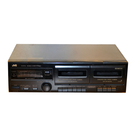
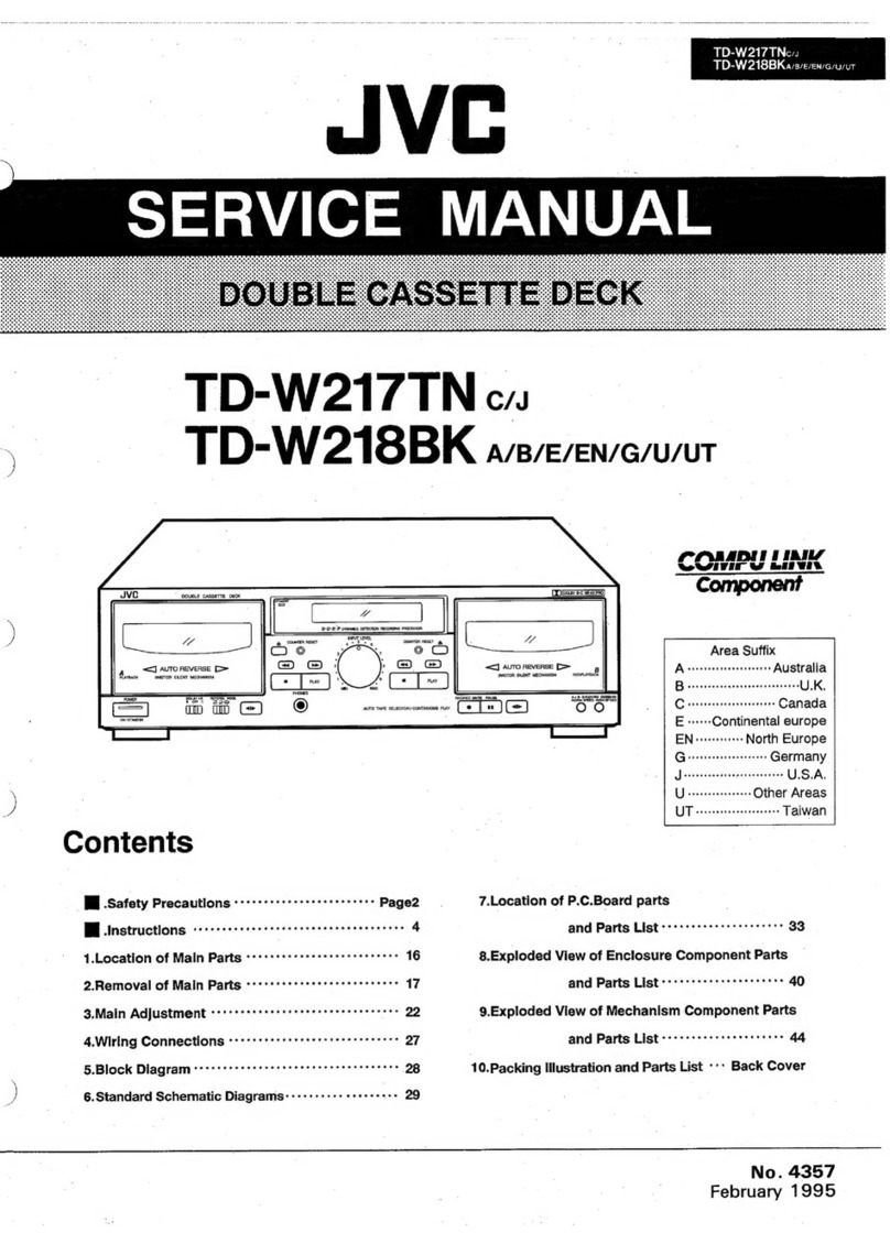
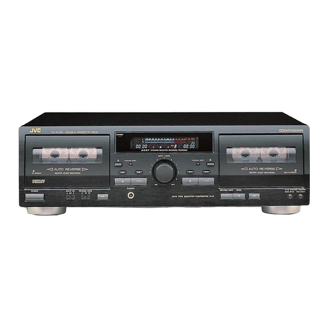
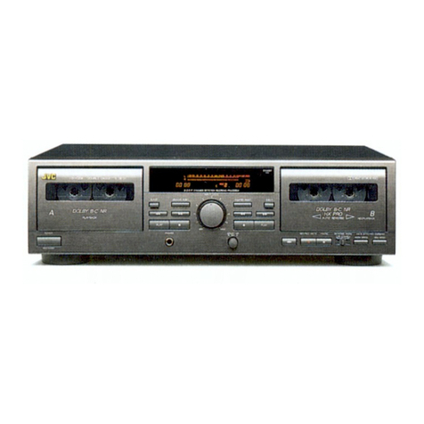
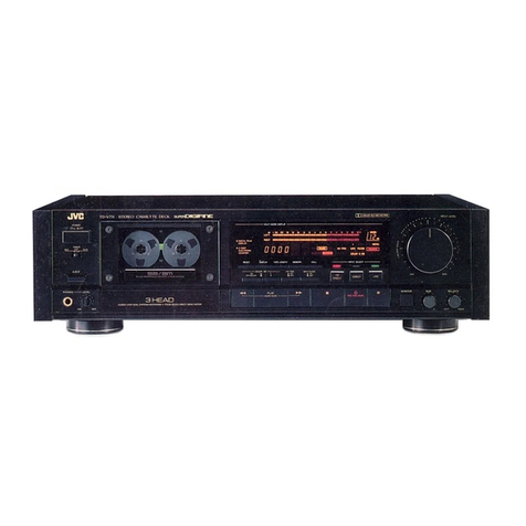
JVC KD-A66 User manual

MODEL
KD-A66
A/B/C/E/J/U
STEREO
CASSETTE
DECK
No.
4193
June
1980

No.
4193
KD-A66A/B/C/E/J/U
|
Contents
Page
Specifications...
0...
ee
es
2
FOQtUFOS
ape
cnt
id
ean
erate
bos
ah
A
a
ei
ee
ea
ea
ee
3
Controls
and
Connections...
......-----00
ee ee
eee
3
Main
Parts
Location...
......
2.002:
eee
ee
eee
4
Description
on
New
Technology.
..........--+-+----
5
Maintenance.
.......
00
eee
eee
eee
ee
eee
10
Removal
of
the
Main
Parts
......-...0202000000
10
Main
Adjustments
........
200002
eee
eee
ee
ee
13
Block
Diagram
2.0...
et
20
Instruction
of
ICs
2...
ee
ee
22
Standard
Schematic
Diagram
(Main
Amp
Circuit)...
....0..0
0000.
eee
eee
23
(Mechanical
Control
Circuit)...
.........2005.
24
(Computer
Circuit)...
2...
2.0.00
ce
eee
oe
tess
25
Specifications
Type
:
Component
stereo
cassette
deck
Track
system
:
4-track,
2-channel
Tape
speed
:
1-7/8
inch/sec
(4.8
cm/sec)
Frequency
response
:
(-20
VU
recording)
Metal
tape
*1
515
—
18,000Hz
25
—
16,000Hz
(+3dB)
SA/Chrome
tape
“2
15—
18,000Hz
25
—
16,000Hz
(+3dB)
SF/Normal
tape
*~3
15
—
17,000Hz
25
—
15,000Hz
(+3dB)
(O
VU
recording)
Metal
tape
SA/Chrome
tape
SF/Normal
tape
25
—
12,500Hz
(+3dB)
25
—.8,000Hz
(+3dB)
25
—8,000Hz
(+3dB)
Frequency
response
when
using
the
computer
B.E.S.T.
tuning
system
(~20
VU
recording)
Metal
tape
SA/Chrome
tape
SF/Normal
tape
40
—
12,500Hz
(+1dB)
40
—
12,500Hz
(+1dB)
40
—
12,500Hz
(+1dB)
Those
values
are
almost
the
same
for
all
types
of
tapes
when
the
computer
B.E.S.T.
tuning
system
is
used.
Note:
*1.....
SCOTCH
METAFINE
or
Equivalent
AD,
TDK
SA
or
Equivalent
Ec
ie
MAXELL
UD
or
Equivalent
S/N
ratio
:
60dB
(from
peak
level,
weighted,
Metal
tape)
The
S/N
is
improved
by
5dB
at
1
kHz
and
by
10dB
above
5kHz
with
ANRS
on.
(DIN
45
500
weighted)
Effect
of
Super
ANRS
:
(Normal
tape)
Improvement
of
S/N:
the
same
as
with
ANRS
Improvement
of
frequency
response:
0
VU
recording;
6dB
at
10kHz
+5
VU
recording;
12dB
at
10kHz
Improvement
of
distortion:
0
VU
recording;
3%
or
less
at
10KHz
+5
VU
recording;
3%
or
less
at
10kHz
Wow
and
flutter
:
0.04%
(WRMS),
0.14%
(DIN
45
500)
Page
Wiring.
(1):
(3)
sins
ON
BS
ee
ea
ee ae
VS
26
~28
Enclosure
Assembly
and
Electrical
Parts
List
......
30
Enclosure
Assembly
and
Electrical
Parts
...........
33
Mechanical
Component
Parts.............0.005-
34
Mechanical
Component
Parts
List.............-
35
Main
Amp
P.W.
Board
Parts...
.....
2.000002
ee
37
Computer
P.W.B.,
Mechanical
Control
P.W.B........
38
Main
Amp
P.W.
Board
Parts
List...............
39
Computer
P.W.
Board
Parts
List..............4.
42
Mecha
Control
P.W.
Board
Parts...
..........0055
45
Mecha
Control
P.W.
Board
Parts
List............-
46
Other
P.W.
Board
Parts...
0...
0.
cee
ee
es
47
Other
P.W.
Board
Parts
List.......-....000005
48
Packing,
Packing
Material
List,
Accessories..........
49
:
65dB
(1kHz)
K3;0.4%,
THD;
1.0%
(metal
tape,
1kHz
OVU)
Crosstalk
Harmonic
distortion
:
Bias
:
AC
bias
Erasure
:
AC
erasure
Heads
:
2SA
(Sen-Alloy)
heads
X-cut
head
for
recording
and
playback
2-Gap
head
for
erasing
:
Electronic
governed
DC
motor
(for
Capstan)
DC
motor
(for
Reel)
:
85
sec.
with
C-60
cassette
:
85
sec.
with
C-60
cassette
:
18
ICs,
77
transistors,
1
FET
52
diodes,
12
LEDs
Motors
Fast
forward
time
Rewind
time
Semiconductors
Input
terminals
Mic
jack
x
2
;
Max.
sensitivity;
0.2mV
(-72dBs)
Matching
impedance;
6002.
~
10k92
Input
jack
x
2;
Min.
input
level;
80mV
(-20cBs)
Input
impedance;
100kQ
Output
terminals
Output
jack
x
2.
;
Output
level;
0
~
500mV
Output
impedance;
5kQ2
Phones
jack
x
1;
Output
level;
0
~
0.5mV
Matching
impedance;
BQ
~
1kQ
:
AC
240V,
50Hz
(KD-A66A)
AC
120V,
60Hz
(KD-A66C/J)
AC
240/220/120V,
50/60Hz
(KD-A66B/E)
AC
240/220/120/100V,
50/60Hz
(KD-A66U)
Power
consumption
:
30W
Power
requirement
Dimensions
:
17-3/4''(450mm)W
4-5/8"
(118mm)H
13”
(331mm)D
(with
feet,
buttons,
switches)
Weight
:
17.4
Ibs
(7.9
kg)
Design
and
specifications
subject
to
change
without
notice.

Features
1.
Controls
and
Connections
»
@
0
12)
®
.
X-cut
SA
(SEN-ALLOY)
Built-in
computer
B.E.S.T.
Tuning
System
for
auto-
matic
adjustment
of
Bias,
Equalization
and
Sensitivity
of
Tape.
.
Metal
tape
compatibility
having
4
tape
select
positions.
.
Full-logic
control
operation
with
2
motor
ID
(Inde-
pendent
Drive)
mechanism.
record/play
head
for
an
improved
frequency
response
over
Permalloy
yet
as
durable
as
ferrite.
_
SA
(SEN-ALLOY)
erase
head
for
perfect
compatibility
with
Metal
Tape.
.
LED
indication
for
cassette
operation
buttons
(REC,
PLAY,
PAUSE)
light
for
the
respective
operation
mode
so as
to
make
checking
easier.
oe
989
10.
11.
12.
KD-A66A/B/C/E/J/U
ANRS,
and
Super
ANRS
for.decreasing
hiss-noise
and
improving
linearity
at
high
frequency.
.
5
LED
multi-peak
level
indicators
for
easy
check
of
the
recording
level.
Continuous
TIMER
STAND-BY
mechanism
for
record-
ing
when
you
are
not
at
home
using
the
REC-OFF-
PLAY
select
switch.
REC
MUTE
button
for
making
a
non-recorded
section
on
the
tape
program.
Memory
switch
for
listening
to
the
same
program
repeatedly.
;
Remote
control
terminal
(R-50E
optional)
(Cramer
Stance
||
PHONES)
cca)
ce
hd
POWER
switch
VU
meter
(left
channel)
VU
meter
(right
channel)
@
Indicators
(see
to
page
4)
@8E268
6600000
Computer
START
button
Computer
PRESET
button
Cassette
holder
Tape
COUNTER/counter
reset
button
MEMORY/AUTO
REW
switch
TIMER
STANDBY
switch
Headphone
jack
[PHONES]
Microphone
jack
(Left
channel)
[MIC-L]
Microphone
jack
(right
channel)
[MIC-R]
ANRS
switch
TAPE
SELECT
switch
INPUT
LEVEL
controls
forward
knob
—
left
channel
rearward
knob
—
right
channel
7]
®
8066
e
®
OUTPUT
LEVEL
control
Cassette
operation
button
<<
>
REW
(Rewind)
button
>>
FF
(fast-forward)
button
>
PLAY
button
a
STOP
button
Oo
REC
(recording)
button
«©
=~
PAUSE
button
REC
MUTE
button
EJECT
button
Voltage
selector
(KD-A66B/C/E/J/U)
Remote
control
socket
LINE
IN
terminals
LINE
OUT
terminals.
Power
cord
No.
4193

KD-A66A/B/C/E/J/U
Indicators
No.
4193
Super
ANRS
indicator
(The
LED
lights
when
super
ANRS
or
ANRS
is
ON)
ANRS
indicator
RUN
(wink)/READY
(glow)
indicator
ERROR
(wink)/PRESET
(glow)
indicator
Multi-peak
level
indicator
@OS0
©
@
Front
panel
assembly
@
DC
solenoid
®
Reel
motor
@
Output
level
control
©
Input
level
contro!
@
VU
meter
(right
channel)
@
VU
meter
(left
channel)
@
Meter
cover
@
Remote
bar
(for
power
switch)
@
Computer
P.W.
Board
assembly
@®
Power
switch
@®
Power
transformer
®
Power
supply
integrant
circuit
P.W.B
assembly
@®
Remote
control
socket
@®
Pin
jack
assembly
(Mechanical
parts)
®
Switch
holder
(left
switch)
@
Supply
reel
assembly
@®
Idler
assembly
@®
Ree!
motor
pully
@
Take-up
reel
assembly
@
Connector
wire
(for
slide
base)
@
Counter
belt
@®
Slide
base
assembly
@
Erase
head
@®
REC/PB
head
@
Pinch
roller
assembly
@
Capstan

KD-A66A/B/C/E/J/U
Description
on
New
Technology
Computer
B.E.S.T.
System
Introduction
The
B.E.S.T.
(Bias
Equalizer
Sensitivity
Tuning)
system
which
is
employed
in
the
KD-A66
is
basically
the
same
as
the
preceding
KD-A8
version
and
has
also
been
provided
with
various
improvements
for
an
enhanced
performance.
The
B.E.S.T.
system
employs
a
microcomputer
for
the
purpose
of
setting
the
proper
optimum
bias
current
and
sensitivity
for
tape.
1.
Bias
As
seen
in
Fig.
1
(the
relationship
between
distortion
rate
and
bias
current
at
the
1
kHz
to
7
kHz
signals),
the
output
level
decreases
when
a
larger
bias
current
is
ap-
plied.
In
this
case
especially,
the
7
kHz
signal
is
sharply
attenuated.
Further,
when
the
bias
current
is
decreased,
the
three-
dimensional
distortion
increases.
Accordingly,
the
bias
current
is
an
important
factor
for
determining
the
frequency
response
and
the
distortion
rate.
It
is
therefore
desirable
that
an
optimum
bias
current
is
set
for
each
tape.
—
Bias
current
(uA)
200
300
400
500
600
700 800
o
=z
D
1KHz
hi
2
Qa
i]
t=
3
i
O
10F
'
T
Set
bias
current
value
;
T7KHz
a3
|
&
2
64
\
£
\
'
c
°F
vot
Third
harmonic
distor-
S44
ar
tion
at
333
Hz
es.
Xe
(250mW/level)
-
|
NU
2
f----4---¥,
Third
harmonic
distor-
QO
24
o’
are
Se
tion
at
1
kHz
Toa
S160
mWitevel)
Fig.
1
2.
Equalizer
As
seen
in
Fig.
2
(with
each
tape
having
its
optimum
bias
current
set),
this
bias
current
is
determined
by
tak-
ing
into
account
the
high-band
molecular
character-
istic
and
distortion
rate
of
the
particular
tape.
Equali-
zation
level
must
then
be
set
to
obtain
a
flat
molecular
START
16sec
16sec
Far:
l2sec
REC-*
Blank
Marker
Approx.
|.2sec
Point
to
which
the
tape
is
rewound
Marker
Point
to
which
the
tape
is
rewound
Bias
sweep
spot
signal
\
characteristic
corresponding
to
that
bias
current.
Until
now,
the
equalization
level
has
been
determined
by
ear
and
an
accurate
tuning
can
only
be
performed
by
experience.
With
this
tuning
system,
the
equalization
level
is
auto-
matically
set
by
a
microcomputer.
Frequency
Distribution
o
mo}
Ovseeeee
denotes
the
type
of
the
tape.
3
5
6
|
NORM
CrOs
Fe-Cr
ax
STD.
UD
STD.
SA
STD
Duad
3
6
4
|
(MAXCE)
(10.4)
(SONY)
eS
a8
2
3
o
:
20
o
=
0
8
-
Boece
to
£
fo}
2
sseecee
eeco00o
oo
ng
Ss
eo
t
Zo
o800000
:
=
$
-4
oe
°
Fis
x
§
xo
°
es
1
:
Fig.
2
Sensitivity
In
tapes,
the
recording
and
reproduction
levels
do
not
necessarily
coincide
with
each
other.
The
difference
between
the
recording
and
reproduction
levels
appears
as
a
beat
in
the
frequency
response
of
a
noise
reduction
circuit
such
as
the
ANRS
circuit,
the
Super
ANRS
circuit,
etc.
In
this
tuning
system,
the
difference
between
these
levels
is
limited
within
1
dB.
Features:
1.
Automatic
setting
of
the
optimum
bias
current
for
the
tape.
2.
Automatic
setting
of
the
level
difference
to
within
+1
dB,
in
the
case
of
10
kHz
high-band
frequency
which
tends
to
differ
between
the
recording
and
reproduction
levels.
3.
Automatic
setting
of
the
tape
sensitivity
to
within
a
+1
dB
error
by
the
ANRS
circuit.
4.
For
tapes
which
cannot
be
automatically
adjusted,
its
sensitivity
is
indicated,
thus
permitting
normal
recording
in
the
state
in
which
respective
values
have
been
preset.
Frequency
characteristic
sensitivity
sweep
spot
signal
L6sec
\1.2sec
Marker
Approx.
|.5sec
Play
REC
—
Blank
~+—
REW
STOP
(the
tape
is
rewound
to
the
vicinity
ii
WIA
of
its
starting
position.)
PLAY
—
-
.
END
+
REW
Fig.
3
No.
4193

KD-A66A/B/C/E/J/U
Operation
The
operation
is
described
in
accordance
with
Fig.
3
(opera-
tional
timing
chart).
1.
No.
4193
Press
the
START
button.
At
this
time,
the
READY
LED
in
the
display
section
flickers,
indicating
that
the
computer
is
in
operation.
The
tape
is
rapidly
fed
at
1.6
sec
to
avoid
the
use
of
the
leader
tape
section.
The
recorder
enters
the
recording
mode.
In
this
mode,
a
blank
recording
(no-signal
recording)
is
performed
for
2.8
sec
to
stabilize
the
mechanical
and
electrical
systems.
Subsequently,
two
marker
signals
and
eight
pairs
of
1
and
7
kHz
test
signals
are
recorded.
At
this
time,
the
bias
current
is
varied
8
steps
every
60
msec
by
+10%
to
-30%
more
than
the
preset
value.
(The
bias
current,
equalization
level
and
tape
sensitivi-
ty
values
are
preset,
each
determined
by
using
a
stand-
ard
tape.)
(Fig.
4)
Preset
value
Bias
current
8
step
bias
current
variations
ome
Markers
ms
1kHz
7
kHz
1
kHz
AN
NK
Ae
Pe
Z
Tone
&
ABBHHEE
Anew
e
eG
ZEZeZceZes
J
Markers
ze
——
1kHz
7
kHz
1121314415
|6|7
60
msec
NY
ON
NNN
REC
Set
point
Fig.
4
The
tape
is
rewound
to
return
to
the
position
at
the
1.6
sec
lapse
point
from
the
beginning
of
the
previous
blank
recording.
Data
on
the
tape
is
reproduced,
and
the
reproduction
levels
of
the
1
and
7
kHz
test
signals
are
compared
in
order
to
properly
determine
their
coinciding
step.
The
microcomputer
detects
these
coincident
steps.
At
this
time,
the
recorder
initiates
recording
and
per-
forms
a
blank
recording
for
2.8
sec.
Subsequently,
the
recorder
records
the
markers,
and
enters
the
12.5
kHz
signal
recording
state
after
recording
the
1
kHz
refer-
ence
level,
and
increasingly
varies
the
equalization
level
of
the
right
channel
by
8
steps
very
60
msec.
Further,
after
recording
the
1
kHz
reference
signal
of
the
left
channel,
the
recorder
increasingly
varies
the
equalization
level.
Next,
to
adjust
the
tape
sensitivity,
the
recorder
increasingly
varies
the
1
kHz
recording
level
by
8
steps
every
60
msec.
The
difference
between
the
smallest
and
largest
levels
is
+4
dB.
(Fig.
5)
As
shown
in
Fig.
2,
the
tape
is
rewound
to
the
position
at
the
1.5
sec
lapse
from
the
beginning
of
recording;
see
item
6.
Right
equalizer
Left
equalizer
Tape
sensitivity
Markers
tight
equalizer
Left
equalizer
Markers
aire!
Set
point
The
recorder
enters
the
reproduction
mode,
and
the
microcomputer
first
compares
the
reproduction
levels
of
the
1
kHz
reference
signal
and
the
12.5
kHz
signal
of
the
right
channel.
In
recording,
since
the
12.5
kHz
signal
is
increasingly
varied
by
the
right
equalizer,
its
reproduction
level
will
coincide
with
that
of
the
1
kHz
reference
signal.
Sub-
sequent
to
storing
this
coincident
point,
the
same
operation
is
also
performed
on
the
left
channel.
Next,
the
tape
sensitivity
is
adjusted.
Prior
to
this,
the
recorder
stores
the
reproduction
level
of
the
1
kHz
reference
signal
of
the
right
channel
during
recording
(item
6),
and
during
reproducing,
seeks
its
coincident
point
with
the
8-step
level
varied
tape
sensitivity
adjust-
ing
signal.
Is
the
SERVICE
switch
at
thé
OFF
position?
Setting
of
preset
vaiues
and
auto
set
values
's
the
START
switch
at
the
ON
position?
Setting
of
frequency
response
sensitivity
in
this
ror
the
first?
Rewinding
the
tape
to
its
starting
position
Setting
of
auto
set
values
|
Fig.
6

9.
Upon
completion
of
tuning
the
equalizer
and
the
tape
sensitivity
(item
8),
the
tape
is
rewound
to
return
to
the
position
as
described
in
item
1.
Then,
the
flickering
READY
LED
lights
continuously.
The
above-mentioned
operation
is
shown
in
Fig.
6.
The
basic
operation
is
as
previously
described.
In
addition,
the
microcomputer
is
provided
for
the
functioning
of
the
tape
deck.
Upon
application
of
power,
the
microcomputer
is
auto-
matically
reset,
thus
resulting
in
a
temporary
stoppage
of
all
output.
SERVICE
switch
This
switch
is
used
to
adjust
the
tape
deck.
The
microcomputer
with
7
adjustment
program
checks
the
generation
of
the
test
signals,
the
variation
of
the
bias
cur-
rent,
the
variation
of
the
equalization
level,
the
variation
of
the
tape
sensitivity,
the
operation
of
the
electronic
mecha-
nism,
and
the
like.
When
the
SERVICE
switch
is
at
the
OFF
position,
the
microcomputer
confirms
that
the
B.E.S.T.
system
is
func-
tioning.
At
this
time,
the
microcomputer
emits
those
auto
set
values
when
the
B.E.S.T.
system
completes
operation
and
emits
the
preset
values
even
if
an
error
occurs
during
the
operation.
Thus,
even
when
the
auto
setting
of
the
res-
pective
values
is
impossible,
normal
recording
is
possible
since
the
preset
values
are
emitted.
Subsequently,
the
microcomputer
waits
for
the
START
switch
to
be
pressed.
When
this
switch
is
pressed,
the
micro-
computer
sets
bias
current,
equalization
level
and
tape
sen-
sitivity
values.
In
this
process,
when
auto
setting
is
impossible,
the
micro-
computer
returns
to
the
bias
setting
mode
to
re-tune.
At
this
time,
when
an
error
recurs,
the
red
PRESET
LED
flick-
ers
and
the
preset
values
are
emitted.
In
addition,
irrespective
of
presence
or
absence
of
error,
the
tape
is
rewound
to
its
starting
position.
As
a
result
of
this,
the
tape
is
effectively
used.
In
normal
auto
setting
of
the
respective
values,
the
rewinding
time
is
about
25
sec.
Operating
Principle
of
Respective
Sections
KD-A66A/B/C/E/J/U
1.
Setting
of
bias
current
Fig.
7
represents
the
bias
current
varying
circuit
em-
ployed
in
the
KD-A66.
The
bias
oscillation
circuit
consisting
of
transistors
X701
and
X702
supplies
current
to
the
erase
head
and
also
activates
the
bias
amplifier
consisting
of
transistors
X703
and
X704.
As
the
supply
voltage
for
this
bias
amplifier
is
changed
in
8
steps
by
a
control
signal
from
the
microcomputer,
the
bias
current
is
changed
in
8
stpes.
When
the
binary
control
signal
from
pins
2,
3
and
4
of
microcomputer
(ICKO1)
is
applied
to
IC701
which
includes
8
electronic
ON/OFF
switches
of
8
circuits,
any
one
circuit
alone
is
turned
on.
At
this
point,
the
base
current
passes
across
a
specific
one
of
transistors
X709
—
X716
turning
it
on.
Concerning
transistor
X708
which
controls
the
supply
voltage
for
the
bias
amplifier,
its
base
voltage
is
deter-
mined
by
a
divided
voltage
by
R728
and
the
associated
collector
resistance
of
X709
to
X716.
The
bias
oscillation
circuit,
which
is
turned
on/off
by
the
BMUTE
signal
from
pin
304
on
the
computer
circuit
board,
is
also
turned
on/off
by
the
NSTOP
signal
(the
control
signal
of
the
brake
and
solenoid)
from
pin
512
on
the
same
board
when
stopping
the
bias
oscillator
circuit
operation
during
the
PAUSE
mode.
+VCCRI
TO
HEAD
Equalization
level
change-over
signal
Tape
sensitivity
change-over
signal
Fig.
8
2.
Setting
of
equalization
level
and
tape
sensitivity
Fig.
8
represents
the
recording
amplifier
section
employed
in
the
KD-A66.
The
input
signal
is
attenuated
by
resistor
RO
and
any
of
resistors
R1
—
R16
and
entered
into
the
specific
transistor.
At
this
time,
a
tape
sensitivity
select
signal
emitted
from
the
microcomputer
causes
the
respective
resistor
in
the
group
of
R1
—
R16
to
be
grounded,
thus
determining
the
attenuation
level.
The
select
signal
is
transmitted
in
the
form
of
4
binary
bits
and
converted
into
decimal
bits.
In
addition,
a
CMOS
IC
incorporat-
ing
analog
switches
is
used
in
the
select
switch
unit
to
protect
the
audio
signal
against
distortion.
This
select
switch
unit
permits
the
change
in
recording
level
of
+4
dB.
No.
4193

KD-A66A/B/C/E/J/U
No.
4193
The
LC
resonance
peaking
circuit
mounted
in
parallel
with
the
emitter
resistor
of
the
recording
amplifier
transistor
boosts
the
high
frequency
of
the
recording
amplifier
transistor.
With
a
normal
tape,
the
output
level
of
a
10
kHz
signal
is
higher
by
about
9
dB
than
that
of
a
1
kHz
signal.
To
avoid
this
problem,
the
selection
of
the
capacitor
in
the
peaking
circuit
is
performed
to
vary
the
compensa-
tion
of
high
frequencies.
In
this
case,
the
microcom-
puter
emits
a
3
binary
bit
signal,
decodes
it
in
8
steps
and
switches
the
appropriate
analog
switch
in
the
CMOS
IC.
Thus,
the
recording
level
is
selected
in
the
range
of
+4
dB.
Fig.
9
Peak
hold
A/D
converting
circuit
In
the
KD-A66,
a
12.5
KHz
frequency
is
selected
as
the
equalizer
tuning
frequency
to
improve
high
band
frequency
response.
In
a
cassette
tape
deck
with
high
frequencies,
the
changes
in
levels
such
as
are
caused
by
dropout,
etc.
are
enlarged
due
to
the
base
material
of
the
cassette
tape
and/or
the
wound
state
of
the
cassette
tape.
If
the
optimim
state
is
decided
by
the
reproduc-
tion
level
such
as
in
the
B.E.S.T.
system,
this
level
change
causes
incorrect
setting
of
the
respective
values.
To
avoid
this
problem
in
the
KD-A66,
a
peak
hold
A/D
converter
has
been
developed
by
the
combination
of
a
peak
hold
circuit
and
a
charge/discharge:
circuit.
The
peak
hold
A/D
converting
circuit
permits
stable
level
detection
even
against
high
frequency
dropout.
Block
diagram
is
shown
in
Fig.
9
and
timing
chart
in
Fig.
10.
The
input
signal
is
classified
into
a
left
or
right
channel
signal
in
IC801
by
the
Lch
signal
from
the
microcom-
puter,
amplified
by
1C802A
and
entered
into
the
peak
hold
circuit
consisting
of
1C802B,
C802,
D802
and
X805,
which
in
turn
detects
the
negative
component
of
the
input
signal
accumulating
at
capacitor
C802.
In
the
KD-A66,
upon
completion
of
the
40
msec
oper-
ation
of
the
peak
hold
circuit,
$3
and
S4
in
1C801
are
turned
on
by
the
ADC
signal
from
the
microcomputer.
Since
$3
functions
to
apply
+5V
to
the
positive
input
side
of
1C802B,
the
output
of
1C802B
is
clipped
to
+5V
and
the
loop
in
the
peak
hold
circuit
is
opened
by
diode
D802.
At
the
same
time
S4
is
turned
on
and
capacitor
C802
is
charged
from
the
constant
current
source
I1.
Since
a
constant
current
is
supplied
to
this
capacitor,
the
volt-
age
in
it
linearly
increases
in
the
form
of
V=I1
x
Time/c
+
Vo
(initia!
voltage).
Since
capacitor
C802
has
been
supplied
with
the
negative
component
of
the
input
signal,
when
the
volt-
age
in
it
rises
with
the
constant
current
charge,
IC803A
detects
the
moment
that
this
voltage
exceeds
OV,
and
transmits
that
detection
signal
as
an
ADT
signal
to
the
microcomputer.
The
microcomputer
measures
the
time
from
when
the
40
msec
peak
hold
operation
is
completed
to
when
the
above
voltage
exceeds
OV,
to
measure
the
signal
level.
Fig.
10
is
the
timing
chart.
Here
the
input
signal
is
sub-
ject
to
peak
holding
during
the
40
msec
period
and
the
constant
current
discharge
is
performed
and
the
state
of
OV
excess
is
shown.
AD1
is
a
normal
signal,
but
this
indicates
that
stable
measuring
is
possible
should
level
change
(decrease)
occur
halfway
as
in
AD2
and
AD3.
WN
A
ADC
Teal
fea
AD3
]
x805
——
:
+
<--|
ae
/
ft
|
|
Marker
signal
detection
When
recording
while
tuning
the
bias
current,
equaliza-
tion
level
and
tape
sensitivity,
marker
signals
first
enter
as
shown
in
Figs
4
and
5.
A
40
msec
signal
of
1
kHz
+50
dB
is
recorded
two
time
as
the
marker
signals
with
a
40
msec
blank
between.
In
the
B.E.S.T.
system,
when
the
tape
is
rewound
after
recording
the
test
signals,
it
returns
to
its
starting
posi-
tion
while
counting
the
pulses
from
the
tape
counter.
This
counting
is
not
as
accurate
as
when
locating
a
60
msec
signal.
For
more
accurate
counting,
the
deck
waits
for
the
said
marker
signals
to
appear
in
the
repro-
duction
state
after
rewinding
the
tape.
After
the
input
signal
is
amplified
by
1C802A
in
Fig.
9,
it
is
compared
with
-0.5V
of
IC803B
in
Fig.
5.
When
this
signal
is
entered,
the
output
from
IC803B
is
inverted
from
+5V
to
-5V,
thus
transmitting
the
arrival
of
the
marker
signals
to
the
microcomputer.
After
detecting
the
marker
signals,
the
microcomputer
chekcs
their
pattern
to
discriminate
the
test
signals,
thereby
preventing
faulty
operation
due
to
external
noise
and
ensuring
accurate
signal
location.

To
Bas
Vottag
heod—*
Ls
sik
ore
ad}
40
}+_TEST
49
LTPLY
Timer
oy
cs
:
519
rome
Mecha
con,
is
=
a
aq
L
TREC.
Terme
BE,
27S)
ae
iNT
START
5
G
ia
tart_sw
Halt
IC
sn
O}Hsenmar
Ho
shop
37
pOTAR
Start
se
poo
me
°
iT
%
ne
5#
7
aR
FF/PLAY
509
OT
EW
/REC
sheet
Prset
su
sos
[}
EWES
wf
MT}.
je
ne.
z
he
‘07
STOP
x»
RLED
|
SIT
so2
PP
MSIOP
fe
ES
ready
x
STus
pay
}
08
Stus
F2
2
307
|}
[7TKH2
Filter
eae
4
F3
we
fi2
Ske
Fitter
46
50
ICK
Ot
%
fa
aes
S
D
!
D
a
S
Fig.
11
Microcomputer
In
the
KD-A66,
the
tuning
function
is
controlled
by
the
42-pin
LSI
microcomputer
which
stores
instructions
of
about
2000
steps
and
processes
normal
instructions
at
10
msec.
The
connection
diagram
is
shown
in
Fig.
11.
In
addition,
its
incorporated
timer
controls
the
timing
of
the
entire
deck.
The
process
is
performed
in
the
P-channel
MOSFET
and
the
output
is
used
in
the
form
of
an
open
drain
type
pull-down.
The
clock
circuit
stably
operates
because
it
consists
of
an
LC
resonance
circuit.
Since
the
microcomputer
is
provided
with
an
interruption
function,
the
pulse
from
the
tape
counter
is
counted
with
interruption.
Auto-stop
The
rotation
pulse
signal
from
the
Hall
IC
is
waveform
rectified
and
differentiated
at
its
leading
and
trailing
edges.
Then,
the
monostabie
multiple
circuit
generates
a
pulse
of
about
20
msec
which
is
in
turn
applied
to
the
interrupt
terminal
INT
of
the
microcomputer.
The
microcomputer
detects
the
tape
position
by
the
rotation
pulse
signal
and
also
generates
an
auto-stop
signal
if
no
signal
is
applied
for 1.5
sec
or
more.
Auto-rewind
circuit
In
the
KD-A66,
when
an
auto-stop
signal
is
emitted
from
the
microcomputer
(ICKOI)
at
the
tape
end
during
playback
or
record,
the
tape
is
automatically
re-
wound
to
the
beginning
and
the
deck
enters
the
PLAY
or
STOP
mode
by
switching
the
MEMORY
switch
(SW55)}.
KD-A66A/B/C/E/J/U
If
the
tape
counter
displays
“999”
halfway,
since
the
deck
also
enters
the
PLAY
or
STOP
mode,
the
data
in
the
tape
can
be
repeatedly
reproduced
between
“‘0°’
and
‘‘999’’.
To
describe
this
operation,
the
MEMORY
switch
(SW55)
is
set
in
the
PLAY
mode.
AT
first,
when
an
auto-stop
signal
is
emitted
from
the
microcomputer
at
the
tape
end
during
playback,
transistor
XKO6
goes
on,
thus
lowering
the
voltage
at
the
auto
termina!
(pin
5)
of
mechanism
contro!
1C51.
At
this
time,
the
auto-
rewind
instruction
is
emitted
from
1C51.
When
the
tape
is
rewound
to
the
beginning
by
this
instruction,
the
auto-stop
instruction
is
emitted
from
pin
12
of
the
microcomputer.
Likewise,
when
the
volt-
age
at
the
AUTO
terminal
(pin
5)
of
I1C51
is
lowered,
the
PLAY
instruction
is
automatically
emitted
from
the
microcomputer.
Next,
to
describe
this
operation,
the
MEMORY
switch
is
set
in
the
STOP
mode,
At
first,
when
an
auto-stop
signal
is
emitted
from
the
microcomputer
at
the
tape
end
during
playback,
transistor
XKO6
goes
on,
thus
lowering
the
voltage
at
the
said
AUTO
terminal.
At
this
time,
the
auto-rewind
instruction
is
emitted
from
1051.
When
the
tape
is
rewound
to
the
beginning
by
this
instruction,
the
auto-stop
instruction
is
emitted
from
pin
12
of
the
microcomputer.
However,
since
the
base
voltage
of
tansistor
X63
is
kept
to
about
1V
during
the
REW
instruciton,
the
emitter
voltage
of
transistor
X63
is
lowered
to
0.2V
when
transistor
XKO6
goes
on.
At
the
same
time,
transistor
X63
goes
on
and
functions
to
pull
the
STOP
terminal
(pin
1)
of
1C51,
thus
entering
the
deck
into
the
STOP
mode.
In
addition,
with
the
MEMORY
switch
in
the
OFF
state,
the
auto-stop
signal
from
the
microcomputer,
when
transistor
XKO6
goes
on,
passes
across
diode
D63
and
also
functions
to
pull
the
STOP
terminal
(pin
1)
of
1C51,
thus
entering
the
deck
into
the
STOP
mode.
Since
the
MEMORY
STOP/PLAY
function
can
be
per-
formed
even
during
the
auto-rewind
operation
by
the
auto-rewind
circuit,
the
data
in
the
tape
can
be
re-
peatedly
reproduced
between
‘999”
in
the
tape
counter
and
the
tape
end.
XKO6
4
[_
VMwis37-001v
|
STOP]
R38
No.
4193

KD-A66A/B/C/E/J/U
Maintenance
To
get
long,
trouble-free
service,
maintenance
is
important.
Do
not
forget
cleaning
and
demagnetizing.
Cleaning
After
Jong
use,
the
heads
and
tape
part
—
capstan,
pinch
roller,
etc.
—
will
become
dirty
with
dust
or
magnetic
parti-
cles.
Dirty
heads
cause
imperfect
erasing
or
high
frequency
drop-off.
A
dirty
capstan
and
pinch
roller
will
cause
un-
stable
tape
speed,
leading
to
increased
wow
and
flutter.
Always
keep
them
clean
by
following
the
procedure
below.
1.
Heads
1)
Push
Eject
button
to
open
the
cassette
holder.
2)
Use
the
head
cleaning
stick-provided
to
wipe
the
sur-
face
where
the
tape
comes
into
contact
with
the
head.
(It
is
effective
to
moisten
the
cotton
with
alcohol.)
2.
Pinch
roller
and
capstan
Do
the
same
method
as
heads.
3.
Cabinet
When
the
cabinet
becomes
dirty,
wipe
it
with
a
soft
cloth
soaked
with
a
neutral
cleaning
solution
of
a
polishing
cloth.
*
Do
not
use
thinner
or
benzine.
Demagnetizing
The
heads
are
made
from
a
material
resistant
to
magnetiza-
tion
but
after
long
use
they
may
become
magnetized.
A
magnet
brought
into
their
vicinity
can
magnetize
the
heads,
causing
excess
noise.
If
noise
seems
to
have
increased,
demagnetize
the
heads
with
a
head
demagnetizer
through
the
following
procedure.
1.
Turn
the
POWER
switch
OFF.
2.
Wrap
the
tip
of
the
demagnetizer
with
vinyl
tape
or
soft
cloth
so
as
not
to
damage
the
head
surface.
Switch
on
the
demagnetizer
and
bring
it
close
to
the
head.
3.
Move
the
tip
of
the
demagnetizer
slowly
first
to
the
left
and
right,
then
up
and
down
in
front
of
the
head.
Gradually
move
it
away
from
the
head
and
switch
it
off
at
a
distance
of
more
than
30
cm
(12”).
4.
The
erase
head
need
not
be
demagnetized.
The
capstan
shaft
and
tape
guide
should
be
demagnetized
in
the
same
way
as
the
record/playback
head.
Do
not
bring
a
magnetized
metallic
object
(a
screw-
driver,
for
example)
near
the
head
as
this
will
increase
noise.
No.
4193
Removal
of
the
Main
Parts
Observe
care
in
handling
the
parts
since
the
parts
are
small
in
size
and
the
distance
between
them
are
short
due
to
a
deck
design
aimed
mainly
at
compactness
and
high
per-
formance.
ENCLOSURE
ASSEMBLY
PARTS
@.
Cassette
door...
.Depress
the
EJECT
button
to
open
the
cassette
door
Slide
off
the
cassette
door
upwards
(about
5
mm)
to
unlock
its
pawls
of
both
sides.
Remove
the
cassette
door
forward.
Eject
button
Fig.
13
@
Topcover......
Remove
4
screws
fastening
the
top
cover.
Control
knobs
(INPUT
LEVEL,
OUTPUT
LEVEL)
and
Lever
Knobs
(ANRS,
TAPE
SELECT)
otalGeiah
©
wl
edn
Bees
Pull
off
them
forward.
Screws
Fig.
14
Lever
knobs
Control
knobs
@
Bottomcover....Remove
5.
screws
fastening
the
bottom
cover.
@
Mecha.
control
switches
assembly
.....
(When
adjusting
or
replacing
REC/PB
heads
or
Erase
head)
Remove
3
screws
positioned
below
the
mecha.
control
switches
(on
the
bottom
of
the
deck)
and
pull
the
control
section
forwards
—
no
need
of
removing
the
front
panel
assembly.
@
Front
plate
assembly
.....
1)
Remove
a
screw
fastening
the
bracket
to
mechanical
assembly.

2)
Remove
4
screws
(3
screws
on
upper
side
and
a
screw
on
bottom
side.)
fastening
the
front
plate
as-
sembly.
Screw
Screws
(for
Mecha
control
switch
ass’y)
(Bottom
View)
ELECTRICAL
PARTS
@
Mechanical
control
P.W.
board
assembly
.....
.Remove
a
screw
fastening
mecha
control
P.W.
board
after
removed
the
mechanical
assembly.
@®
Main
amp
P.W.
board
assembly
.....
1)
Remove
2
screws
fastening
the
lever
switches
(ANRS,
TAPE
SELECT)
2)
Remove
2
washers
and
2
nuts
fastening
variable
resistors
for
INPUT
LEVEL
and
OUTPUT
LEVEL.
Washers
and
nuts
Screws
Fig.
18
3)
Remove
4
screws
fastening
the
main
amp
P.W.
board.
(on
bottom
side)
Screws
Screws
Main
Amp
P.W.B
assy
Front
Fig.
19
|
ko-assala/cetsy
@
Computer
P.W.
board
assembly
1)
Remove
3
screws
fastening
the
Computer
P.W.
Board
2)
Remove
the
pawl
(P.W.B
holder)
and
open
the
computer
P.W.
Board
on
the
front
side.
Computer
P.W.B
Screws
q
(Top
View)
Fig.
20
MECHANICAL
ASSEMBLY
1.
Remove
a
screw
fastening
the
bracket
of
mechanical
assy.
(See
Fig.
15
of
page
10)
2.
Remove
2
screws
a)
fastening
the
front
bracket.
(up-
per
side)
3.
Remove
a
screw
(2)
fastening
the
front
bracket.
(right
side)
4.
Remove
4
screws
8)
fastening
the
amp
chassis.
(2
screws
each)
5.
Pull
out the
mechanical
assembly
to
rear
side,
pushing
the
shift
arm
from
upper
side.
(holding
the
shift
lever
tip
to
upper
side
for
not
touch
it
to
the
counter
belt.)
(Right
side
view)
Screw
(@)
1K
rot
|
Screw
@)
>
a7
Screws
3
Screw
(@)
SE
HS
Screw
@
|
fa
Front
(Top
View)
Fig.
21
Note:
:
When
assembly
the
mechanical
ass’y
.....
Insert
the
mechan-
ical
ass’y
to
front
bracket
from
rear
side,
pushing
the
shift
arm
from
upper
side
(holding
the
shift
lever
tip
to
upper
side)
and
sliding
the
mechanical
ass’y
on
the
amp
chassis,
and
then,
fasten
each
screws
in
the
same
method
as
at
removing,
after
to
check
the
shift
lever
tip
position
to
front
of
the
eject
bracket.
When
fastening
the
shift
arm,
push
the
eject
button
to
check
the
switch
(left
side
of
shift
arm)
operation.
No.
4193

KD-A66A/B/C/E/J/U
Front
side
Shift
arm
Shift
lever
Eject
fever
at
Rear
side
Fig.
22
Front
side
Touch
the
shift
fever
on
the
front
side
of
the
eject
lever.
|
Shift
lever
|
Eject
lever
Fig.
23
MECHANICAL
PARTS
1.
REC/PB
head
.....
Remove
a
screw
Work
loose
a
screw
(2)
for
adjustment.
2.
Erase
head
.....
Remove
a
screw
®
:
Remove
a
screw
(4)
for
adjustment.
3.
Pinch
roller
arm
ass’y
.....
Remove
an
E-ring
©
holding
its
assembly.
Pull
it
off
from
the
shaft.
4.
Supply
reel
disc
.....
Pull
out
the
reel
disc
stopper
®and
pull
out
its
disc
from
shaft.
5.
Take-up
reel
disc
.....
Pull
out
the
reel
disc
stopper
DM
and
remove
the
counter
belt,
pull
out
its
disc
from
shaft.
Note:
(1)
Remove
the
reel
disc
stoppers
with
a
piece
of
sheet
metal
inserted
between
the
reel
disc
and
stopper,
when
assembling
the
reel
disc,
the
stopper
need
a
new
parts
(the
stopper
cannot
use
again).
(2)
Be
careful
not
to
stain
the
counter
belt.
7.
Reel
motor
.....
Remove
3
screws
(8)
fastening
the
reel
motor.
8.
Capstan
motor
.....
1)
Remove
a
screw
©
fastening
the
rubber
stopper.
2)
Remove
the
capstan
belt
from
the
motor
pulley.
3)
To
remove
the
motor,
turn
it
in
counterclockwise
direction
and
pull
it
out
backward
(with
3
cushions
and
3
screws
for
fastening
the
motor).
No.
4193
ibe.
Note:
When
replacing
the
motor,
check
the
following
points.
(1)
Is
the
motor
placed
in
correct
position?
(Don’t
make
the
motor’s
position
deflective.)
(2).
Does
the
capstan
belt
run
in
the
center
of
the
motor
pulley?
(Top
View)
Fig.
24
Capstan
motor
(Rear
View)
Fig.
25
=

KD-A66A/B/C/E/J/U
Main
Adjustments
[1]
Equipment
and
measuring
instruments
used
for
adjustment
1.
Electrical
adjustment
1)
Electronic
voltmeter
2)
Audio
frequency
oscillator
pete
(range:
50—20
kHz
and
output
0
dB
with
impedance
Audio
Freq.
Osc.
OMe
p
6002)
Attenuator
tg
3)
Attenuator
4)
Standard
tapes
for
REC/PB
Maxell
UD
—
SF
tape
.
TDK
SA
-
SA
tape
|
or
equivalent
SCOTCH
METAFINE
—
Metal
tape
5)
Reference
tapes
for
playback
(JVC
Test
Tape)
VTT-658
(for
head
azimuth
adj.)
VTT-656
(for
motor
speed,
wow
flutter
adj.)
VTT-664
(for
Reference
Level
1
kHz)
VTT-675N
(for
playback
frequency
response)
6)
Resistors
1002
(for
measurement
of
the
bias
current)
6002
(for
attenuator
matching)
2.
Mechanical
adjustment
1)
Gauge
for
checking
the
head
position.
2)
Torque
gauge
3)
Blank
tape
(C-120)
for
tape
running
checker.
OUTPUT
LINE
OUT
[11]
Adjustment
and
repair
of
the
mechanism
TROUBLESHOOTING
HINTS
2.
Tape-to-head
contact
adjustment
1.
Azimuth
adjustment
and
head
replacement
1)
Turn
the
adjusting
screw
for
0°
1)
Remove
the
wires
of
the
control
switches
from
the
aligning
the
erase
head
until
it
wire
clamps
after
having
removed
the
top
cover.
stops.
Then,
turn
the
screw
in
é
2)
Remove
3
screws
positioned
below
the
control
the
reverse
direction
by
225°
ras
switches
(on
the
bottom
of
the
deck)
and
pull
the
(a
5/8
revolution).
control
section
forwards.
2)
Check
the
tape-to-head
contact
using
a
C-120
tape
3)
With
the
control
section
pulled
out,
azimuth
adjust-
having
pads.
ment
and/or
head
replacement
can
be
performed.
3)
Check
it
again
with
a
Metal
tape.
With
the
JVC
cassette
deck
series
of
KD-A6,
KD-A5
Checking
method:
and
KD-A8
models,
the
adjustment
of
replacement
Record
a
400
Hz
or
1
kHz
signal
with
O
VU
+
20
cB.
can
be
performed
more
easily
than
with
conventional
Erase
the
recording.
Checking
if
the
erasing
is
satis-
cassette
decks
which
require
removal
of
the
entire
factorily
performed.
mechanical
section
for
the
adjustments
and/or
replace-
4)
After
adjustment,
apply
screw
bond
on
the
adjusting
ments.
screw
to
prevent
its
loosening.
(Adjust
the
mechanism
or
confirm
that
it
is
in
normal
operating
condition
prior
to
the
adjustment
of
the
electrical
circuit.)
point
value
Adjusting
1.
Connect
an
electronic
voltmeter
to
Screw
®
Maximum
lf
the
head
is
worn,
disconnect-
record/playback
the
LINE
OUT
terminals.
ed
or
exceedingly
magnetized
so
head
position
2.
Playback
the
VTT-658
test
tape.
as
not
to
provide
the
necessary
3.
Adjsut
the
head
angle
with
the
characteristics,
replace
it
with
a
screw
@®
until
the
reading
of
the
new
one.
electronic
voltmeter
becomes
maxi-
After
replacement,
the
head
mum
for
both
channels.
position
adjustment
as
well
as
the
4.
After
adjusting,
set
the
screw
with
playback
level
adjustment,
the
screw
bond.
bias
current
adjustment
and
the
recording
level
adjustment
are
all
necessary.
If
the
output
difference
between
the
left
and
right
channels
exce-
eds
3—4
dB,
the
head
is
defect-
ive.
Replace
it
with
a
new
one.
—13—
No.
4193

KD-A66A/B/C/E/J/U
point
value
Employ
a
special
cassette
(C-120)
Screw
©
from
which
parts
of
the
casing,
where
the
erase
head,
record/playback
head
and
capstan
engage,
has
been
cut
away.
Perform
tape
transport
with
the
cas-
sette
tape.
Adjust-the
screw
©
until
the
tape
runs
in
the
center
of
the
erase
head
tape
guide.
(See
“Troubleshooting
hints’’
afore-
said.)
Incorrect
Correct
Tape
guide
Tape
guide
=
EF
Tape
guide
LL.
Be
sure
to
perform
this
adjust-
ment
after
replacing
the
erase
head.
Adjusting
erase
head
height
Adjusting
motor)
Connect
a
speed
meter
(an
electronic
Semi-
3000
Hz
If
the
speed
meter
functions
as
a
speed
counter)
to
the
LINE
OUT
terminals.
fixed
wow
and
flutter
meter,
also,
Playback
the
VTT-656
test
tape.
resistor
connect
the
deck
to
the
INPUT
Adjust
the
semi-fixed
resistor
in
the
in
the
terminals
of
the
meter.
motor
until
the
reading
of
the
speed
motor
meter
is
3000
Hz.
Checking
play-
Employ
a
torque
testing
cassette
tape
40—70
If
the
standard
torque
is
not
obtained,
replace
the
take-up
disc
assembly.
for
the
checking,
or
remove
the
cas-
sette
cover
and
use
a
torque
gauge.
back
torque
More
than
70gr-cm
If
the
standard
torque
is
not
obtained,
perform
the
following.
1.
Clean
the
capstan
belt,
the
idler
circumference,
the
motor
pulley,
the
take-up
reel
disc
circumference,
the
flywheel
circumference,
etc.
.
Replace
the
belt
and
idler.
Measure
the
torque
in
the
fast
forward
mode
in
the
same
manner
as
in
the
above.
Checking
fast
forward
torque
Checking
More
than
rewind
torque
Measure
the
torque
in
the
rewind
mode
in
the
same
manner
as
in
the
above.
If
the
standard
torque
is
not
obtained,
clean
the
capstan
belt,
idler,
motor
pulley,
flywheel
circumference,
rewinding
idler
circumference,
left
reel
disc
circumference,
etc.
Connect
a
wow
and
flutter
meter
to
LINE
OUT
terminals.
Playback
the
VTT-656
test
tape.
Check
to
see
if
the
reading
of
the
meter
is
within
0.05%
(WRMS).
If
the
reading
becomes
moving
value
even
if
conforming
to
the
standard,
a
re-claim
may
be
raised.
Repairs
are
necessary.
Checking
wow
and
flutter
No.
4193
AAS
sie

KD-A66A/B/C/E/J/U
[It]
Repair
of
wow
flutter
If
wow
and
flutter
increase,
check
the
following
points.
If
there
is
defect
in
revolving
parts,
the
wow
and
flutter
generated
will
increase
in
proportion
to
the
number
of
revolutions.
Play
a
300
Hz
test
tape,
and
defective
part
can
be
detected
from
the
sound.
[section
[woe
—SSC*~dSC“‘“‘CSO™SCS™C*~#w
w=SCSCS~*S
Capstan
|
Capstan
shaft
has
excessive
run-out.
Replace
flywheel.
Flywheel!
turns
heavily.
Clean
the
capstan
shaft
and
the
groove
in
the
flywheel.
(shaft
seisure,
thrust
play,
etc.)
Apply
oil
to
the
metal
position.
Replace
the
capstan
assembly.
Pinch
roller
Replace
pinch
roller,
or
pinch
roller
spring.
Clean
the
pinch
roljer
or
apply
oil
to
the
rotary
shaft.
Adjust
the
pinch
roller
so
that
it
is
parallel
with
the
capstan
shaft.
Replace
the
pinch
roller
spring.
Belt
Belt
has
undue
run-out.
Clean
the
belt.
Belt
is
dirty
or
slippery.
Replace
the
belt.
Back
Back
tension
is
irregular,
or
back
tension
is
too
Replace
back
tension
spring
(under
supply
disc).
tension
|
strong.
Motor
Motor
shaft
has
undue
run-out.
Replace
the
motor.
Motor
pulley
is
oily
and
dusty.
Clean
the
motor
pulley.
[IV]
Electrical
adjustment
location
Main
Amp
P.W.
Board
Rough
rotation
(Deformation
scratches,
or
dust)
The
angular
position
of
the
pinch
roller
is
not
correct.
The
pinch
roller
pressure
is
not
correct.
VRIOS
(
—;—L—For
VU
meter
deflection
adjustment
_
|
eturning
in
the
direction
of
the
arrow
C+
increases
the
deflection
angles)
VR205
|
For
playback
level
adjustment
(Turning
in
the
direction
of
the
arrow
vRio2
increases
the
playback
levels)
R
(
(CJvreo2
Ceo!
oe
t
VR40l
For
playback
frequency
response
adjustment.
(Turning
in
the
direction
of
the
arrow
For
bias
current
adjustment
increases
in
the
signal
current)
(Turning
in
the
direction
of
the
arrow
increases
the
bias
current
value}
Front
¢
a45=

KD-A66A/B/C/E/J/U
{[V]
Electrical
circuit
adjustment
procedure
In
th
steps
marked
by
an
asterisk
(*),
adjustment
should
be
performed,
however,
only
checking
is
sufficient
with
steps
other
than
those.
1*
.
Play
back
the
VTT-664
Reference
tape
(1
kHz)
with
the
tape
select
switch
set
to
the
SF/NORM
posi-
tion.
Adjust
VR102
and
VR202
until
the
LINE
OUT
becomes
about
—4
dBs.
Playback
test
tape
VTT-675N
(1
kHz,
10
kHz)
for
following
adjustment.
1)
Adjsut
VR101
and
VR201
so
that
10
kHz
signal
and
1
kHz
signal
gains
become
flat
response.
Adjusting
playback
level
Playback
frequency
response
.
Set
the
cassette
deck
to
its
record-
ing
mode.
Apply
a
1
kHz,
approx.
—10
dBs
signal
to
the
LINE
IN
terminals.
Adjust
the
recording
!evel
controls
until
the
signal
is
available
at
—4
dBs
at
the
LINE
OUT
terminals.
Adjust
VR105
and
VR205
until
the
VU
meters
deflect
to
0.
Record
1
kHz,
50
Hz
and
12.5
kHz
signals
at
an
input
level
of
O
VU
to
—20
aB.
Playback
the
tape.
Check
to
see
that
the
50
Hz
and
12.5
kHz
singal
output
deviations
fall
within
the
standard
range,
using
the
1
kHz
singal
output
as
a
reference.
Adjusting
VU
meter
deflection
Checking
record/
playback
frequency
response
Increase
in
high
frequencies
(with
a
small
bias
current)
~
Optimum
level
Decrease
in
high
frequencies
(with
a
larger
bias
current)
12.5kHz
Response
(dB)
50Hz
1kHz
Frequency
(Hz)
.
Apply
a
1
kHz,
approx.
—10
dB
Signal
to
the
LINE
IN
terminals.
Adjust
the
recording
level
controls
until
the
signal
is
available
at
—4dBs
at
the
LINE
OUT
termianls.
.
After
checking
to
see
if
the
VU
meters
become
to
0,
record
the
signal
applied
to
both
left
and
right
channels
using
normal
tape.
.
Play
back
the
recording
part.
Per-
form
the
recording
signal
adjust-
ment
with
VR501
and
VR601
so
that
the
VU
meters
become
to
0.
Adjusting
recording
level
Adjusting
|
Standard
point
value
VR102,
202
VR101,
201
VR105,
205
Adjustment
should
be
performed
in
the
order
of
steps
1,2,
3,
....
Perform
this
adjustment
with
the
ANRS
switch
set
to
OFF
and
output
level
contro!
set
to
maximum.
This
adjustment
becomes
neces-
sary
when
a
change
in
playback
level
results
(for
example,
due
to
head
replacement).
—4
dBs
(0.5V)
Reference
frequency
\kHz
O0+£2dB
at
10kHz
Reference
frequency;
1
kHz
Perform
the
adjustment
when
the
parts
are
replaced.
This
checking
should
be
perform-
ed
for
normal,
chrome
and
metal
tapes
and
for
both
right
and
left
channels.
0+3dB
1.
Bias
current
adjustment
for
a
at
50
Hz
cassette
deck
should
general-
0+3dB
ly
be
performed
referring
to
the
record/playback
frequen-
cy
response.
This
is
because
the
frequency
response
of
a
cassette
deck
depends
more
greatly
upon
the
bias
current
than
does
that
of
an
open
reel
deck.
The
current
measuring
method
described
below
is
an
alternative
one.
If
the
bias
current
is
not
properly
adjusted,
the
record
and
playback
characteristics
becomes
as
shown
left.
at
12.5
kHz
The
level
difference
between
left
and
right
channels
for
SF/
NORM
tape,
chrome
tape
and
metal
tape
should
be
less
than
1
dB
(1
VU).
Perform
the
adjust-
ment
usign
a
normal
tape,
level
difference
between
recording
and
playback
for
SA/CrO2
and
metal
tapes,
should
be
less
than
1.5dB,
and
that
between
left
and
right
channels
shold
also
be
less
than
1
dB.

KD-A66A/B/C/E/J/U
Ca
es
“point
point
value
Checking
.
Record
a
1
kHz,
—4
dBs
signal
to
SF/NORM
Be
sure
to
perform
this
adjust-
record/
LINE
IN
terminals
and
perform
re-
tape;
ment
following
bias
curret
and
playback
cording
with
the
VU
meter
Less
than
recording
level
adjustments.
distortion
becomes
to
0.
2.5%
2.
Play
back
the
recorded
part.
Check
SA/CrO2
tape;
the
output
with
a
distortion
meter
Less
than
3%
to
see
if
the
value
conforms
to
the
Metal
tape;
standard
value.
Less
than
2%
.
Record
a
1
kHz,
0
VU
signal.
SF/NORM,
Apply
an
output
(—72
dBs)
to
Stop
the
input
by
disconnecting
SA/CrO2
and
the
MIC
terminals
with
the
Checking
signal
to
noise
from
the
terminal
to
perform
non-
Metal
tapes;
recording
level
controls
set
to
ratio
in
signal
recording.
More
than
maximum
so
that
the
VU
meter
recording/
|
2.
Playback
the
recorded
part.
42
dB
becomes
to
0.
playback
Measure
the
0
VU
recording
output
and
the
non-signal
recording
output
for
comparison
using
an
electronic
voltmeter.
Check
to
see
if
the
value
conforms
to
the
standard
value.
Checking
.
Apply
a
1
kHz
signal
to
the
LINE
erasing
IN
terminals.
Adjust
the
recording
coefficient
level
controls
until
the
VU
meter
becomes
to
0.
.
Perform
recording
with
the
signal
enhanced
by
20
dB.
.
Erase
a
part
of
the
recording.
.
Measure
the
output
difference
be-
tween
the
erased
part
and
non-
erased
part
to
compare
with
an
electronic
voltmeter.
For
the
measuring,
connect
a
band
pass
filter
between
the
deck
and
the
electronic
volt-
meter.
Input
(1kHz
OVU
+
20dB)
Tape
deck
(recording,
erasing)
Electronic
voltmeter
Band
pass
filter
More
than
65
dB
-a7-
|
No.
4193

KD-A66A/B/C/E/J/U
Computer
P.W.
Board
meat
[
J750
raid
VRFOI
(
5
bors
For
recording
level
adjustment
(Turning
in
the
direction
of
the
arrow
VRFO2
increases
the
recording
levels.)
(Com
—}
For
reference
signal
output
level
adjustment
VRFO3
poe
: 7
|
(Turning
in
the
direction
of
the
arrow
(
—IKHz
—.
increases
the
output
levels.)
—-
ca
A/D
output
adjustment
vreo|
{Turning
in
the
direction
of
the
arrow
increases
the
output
levels.)
Clock
OSC
400
kHz
Test
point
a
Ne
~~)
Adjustment
by
Computer
Tester
Tester
for
KD-A8
plus
Relaying
Connection
(Using
the
same
quality
assurance
of
the
radio
cassette
recorder)
Adjusting
method
Adjustment
Standard
point
(s)
value
(s)
Adjust
coil
LKO1
with
a
counter
connected
LKO1
400
kHz
to
CLI
on
the
computer
circuit
board
so
that
+5
kHz
this
clock
pulse
is
400
kHz.
Set
the
computer
tester
to
the
TEST
Test
program:
0
2
|Computer
oscillation
and
MANUAL
modes.
2)
Set
the
TEST
MODE
switch
S3
of
the
Computer
computer
tester
ON,
press
the
PRESET
circuit
switch,
then
set
the
OPERATION
board
307
switch
to
REC
PAUSE.
3)
Obtain
the
switchable
output
of
1
kHz—
7
kHz—12.5
kHz
by
pressing
the
START
switch.
4)
With
the
switchable
output
set
to
|
kHz,
adjust
VRFO3
on
the
computer
circuit
board
so
that
the
input
level
is
-37
dB.
5)
With
the
switchable
output
set
to
7
kHz
adjust
VRFO2
on
the
computer
circuit
board
so
that
the
input
level
is
-36.5
dB.
6)
With
the
switchable
output
set
to
12.5
kHz,
adjust
VRFOI
on
the
computer
circuit
board
so
thet
the
input
level
is
-36.5
dB.
Test
point
-37dB
at
1kHz
VRFO3
VRFO2
-36.5dB
VRFO1
~36.5dB
at
12.5kHz
No.
4193
a4

KD-A66A/B/C/E/J/U
Adjustment
Standard
Set
the
computer
tester
to
the
TEST
Test
program:
3
and
MANUAL
modes,
set
the
test
program
(TEST
PRO)
switch
S3
to
ON,
then
set
both
S4
and
$5
to
ON.
2)
Press
the
PRESET
switch,
then
set
the
OPERATION
swtich
to
REC
PAUSE.
3)
Adjust
VR801
so
that
‘’58”
is
display-
ed
on
the
LEVEL
DETECT
indicator
of
the
computer
tester.
4)
After
the
above
Adjustment,
confirm
that
the
A/D
conversion
time
is
about
8
msec
in
the
A/D
converted
waveform
at
test
point
TP.
Set
the
computer
tester
to
the
TEST
and
MANUAL
modes,
set
the
test
program
(TEST
PRO)
switch
$3
to
ON,
then
set
the
both
$4
and
S5
to
ON.
2)
Set
the
OPERATION
switch
to
REC
PAUSE,
then
draw
out
the
post
pin.
3)
Set
the
test
program
swtich
S1to
+5V
and
apply
a
71
KHz
signal
to
LINE
IN
Then,
when
the
outut
level
of
this
signal
at
LINE
OUT
is
set
to
8
dB,
it
shall
vary
at
test
pins
and
205]
on
the
computer
circuit
board
as
shown
in
the
diagram
below.
Confirm
that
the
output
level
increases
in
steps
in
the
range
of
about
—4
dB
to
+4
dB
against
the
preset
value.
3
|Analog/
-15V+03V
Approx.
8m
sec
(Test
point:
A/D)
Test
program
switch:
3
Set
the
computer
tester
to
the
TEST
and
MANUAL
modes,
set
the
test
program
(TEST
PRO)
switch
S3
to
ON,
then
set
S4
to
ON.
2)
Press
the
PRESET
switch,
set
the
OPERATION
switch
to
REC
PAUSE,
then
draw
out
post
pin
H
and
set
S$1to
+5V.
3)
Apply
a
10
kHz
signal
to
LINE
IN.
Then,
when
the
output
level
of
this
signal
at
LINE
OUT
is
set
to
8
dB,
it
shall
vary
as
shown
in
the
diagram
below
when
measuring
the
signal
cur-
rent
at
the
record/playback
head.
With
a
normal
tape,
confirm
that
the
output
level
varies
in
the
same
increment
in
the
range
of
about
—4dB
to
+4dB.
(10
kHz,
steps
0
—
7)
Equalization
level
selec-
tion
operation
aust
a
se
a
Test
program:
2
Connect
a
100Q
resistor
between
the
blue
wire
of
the
record/playback
head
and
the
head
terminal,
then
insert
a
recordable
tape.
2)
Set
the
frequency
to
82
kHz
+
1
kHz
by
turning
the
oscillation
coil
L701
with
the
deck
set
in
the
REC/PLAY
mode.
3)
Raise
the
output
to
maximum
by
turning
coil
L702.
4)
Reduce
the
bias
current
leakage
at
test
points
TP
201
and
101
ro
less
than
—30
dB
by
coils
L104
and
L204.
5)
Set
the
computer
tester
to
the
TEST
and
MANUAL
modes,
set
the
test
program
(TEST
PRO)
switch
S3
to
on,
and
set
S5
to
ON.
Next,
press
the
PRESET
swtich,
then
set
the
deck
to
the
REC/PLAY
mode.
Confirm
that
the
bias
current
varies
in
the
range
of
10
to
30
R
of
the
initial
value.
current
regulation
Test
program:
1
—19—
No.
4193

KD-A66A/B/C/E/J/U
Block
Diagram
Recording
system
ANRS,
Super
ANRS
Circuit
ICA
O|
AN7362
Q
88
Meter
Adg.
VU_meter
>
Input
level
OUTPUT
;
converter
circuit
IC
801,802,803
REC
Head
E
Head
Playback
system
No.
4193
ANRS,
Super
ANRS
Circuit
Head
Amp
PB
EQ
Adj,
ICAO
ANF
AN
7362
Meter
Adj.
VU_meter
Multi-peak
level
Amp
To
pews.
a
-
Computer
PW.Board
AN
Iti-peak_
level
Amp
SUPER
9
38
(To
ee
To
Multi-peak
level
Indicator
|
To
Muiti-peak
level
Indicator
|
!
|
|
OUT
PUT
ic
|
level
control
Headphone
ae
a
LINE
OUT
L
This manual suits for next models
6
Table of contents
Other JVC Cassette Player manuals