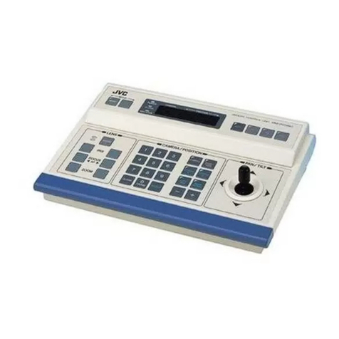
JVC RM-P200 User manual

Jan.
1988
No.
6463
JVC
Service
Manual
REMOTE
CONTROL
UNIT
mMopeEL
RM-P200
CAMERA
CABLE
moor.
VC=P110/-P112/-P113/-P114
CABLE
ADAPTER
(Coupling
Connector)
move.
KA=-280
VICTOR
COMPANY
OF
JAPAN,
LIMITED

No.
6463
JVC
Service
Manual
mopeL.
RM-P200
“aaa
aaa
oe

TABLE
OF
CONTENTS
Section
Title
Page
Important
Safety
Precautions
INSTRUCTIONS
1c.
“DISASSEMBLY.
o5.cccceene
edo
See
Sed
Ses
wa
se
da
ee
de
en
eee
1-1
2.
ADJUSTMENT
PROCEDURE
..........
0...
0...
ec
ee
ee ee
es
2-1
se
“REPACKING
vasiscitek
wig
ike
Ue
he
re
ee
eee
Behe
ae
Reel
ele
Oa
en
e's
3-1
4.
EXPLODED
VIEWAND
PARTS
LIST
.........
0.0...
e
cee
eee
eee
4-1
5.
CHARTS
AND
DIAGRAMS
.......
0...
0.
eee
eee
eee
eee
5-1
6.
ELECTRICAL
PARTS
LIST
..............
shea
eh
Hue
Relea
whan
gies
6-1
CAMERA
CABLE
VC-P110
series/CABLE
ADAPTER
KA-280
1.
WIRING:
4eoie
yeas
eee
aegal
ee
Dhak
4a
eee
wd
BAe
ated
1-1
22:
(REPACKING?
6
6
gaa
ccge
wince
et
Shai
NA
ale
ait
ue
dae
tink
1-1
COPYRIGHT
©
1987
VICTOR
COMPANY
OF
JAPAN,
LTD.
Printed
in
Japan

Important
Safety
Precautions
Prior
to
shipment
from
the
factory,
JVC
products
are
strictly
inspected
to
conform
with
the
recognized
product
safety
and
electrical
codes
of
the
countries
in
which
they
are
to
be
sold.
However,
in
order
to
maintain
such
compliance,
it
is
equally
important
to
implement
the
following
precautions
when
a
set
is
being
serviced.
@
Precautions
during
Servicing
Locations
requiring
special
caution
are
denoted
by
labels
and
10.
Products
using
cathode
ray
tubes
(CRTs)
inscriptions
on
the
cabinet,
chassis
and
certain
parts
of
the
product.
When
performing
service,
be
sure
to
read
and
comply
with
these
and
other
cautionary
notices
appearing
in
the
opera-
tion
and
service
manuals.
Parts
identified
by
the
/\
symbol
and
shaded
(
)
parts
are
critical
for
safety.
Replace
only
with
specified
part
numbers.
Note:
Parts
in
this
category
also
include
those
specified
to
comply
with
X-ray
emission
standards
for
products
using
cathode
ray
tubes
and
those
specified
for
compliance
with
various
regulations
regarding
spurious
radiation
emission.
Use
specified
internal
wiring.
Note
especially:
1)
Wires
covered
with
PVC
tubing
2)
Double
insulated
wires
3)
High
voltage
leads
.
Use
specified
insulating
materials
for
hazardous
live
parts.
Note
especially:
1)
Insulation
Tape
2)
PVC
tubing
3)
Spacers
4)
Insulation
sheets
for
transistors
.
When
replacing
AC
primary
side
components
(transformers,
power
cords,
noise
blocking
capacitors,
etc.)
wrap
ends
of
wires
securely
about
the
terminals
before
soldering.
‘ire
Bo
47
Fig.
1
.
Observe
that
wires
do
not
contact
heat
producing
parts
(heat-
sinks,
oxide
metal
film
resistors,
fusible
resistors,
etc.)
.
Check
that
replaced
wires
do
not
contact
sharp
edged
or
pointed
parts.
.
When
a
power
cord
has
been
replaced,
check
that
10—15
kg
of
force
in
any
direction
will
not
loosen
it.
Power
cord
Fig.
2
9.
Also
check
areas
surrounding
repaired
locations.
In
regard
to
such
products,
the
cathode
ray
tubes
themselves,
the
high
voltage
circuits,
and
related
circuits
are
specified
for
compliance
with
recognized
codes
pertaining
to
X-ray
emission.
Consequently,
when
servicing
these
products,
replace
the
cath-
ode
ray
tubes
and
other
parts
with
oniy
the
specified
parts.
Under
no
circumstances
attempt
to
modify
these
circuits.
Unauthorized
modification
can
increase
the
high
voltage
value
and
cause
X-ray
emission
from
the
cathode
ray
tube.
.
Crimp
type
wire
connector
In
such
cases
as
when
replacing
the
power
transformer
in
sets
where
the
connections
between
the
power
cord
and
power
transformer
primary
lead
wires
are
performed
using
crimp
type
connectors,
if
replacing
the
connectors
is
unavoidable,
in
order
to
prevent
safety
hazards,
perform
carefully
and
precisely
according
to
the
following
steps.
1)
Connector
part
number
:
E03830-001
2)
Required
tool
:
Connector
crimping
tool
of
the
proper
type
which
wil!
not
damage
insulated
parts.
3)
Replacement
procedure
(1)
Remove
the
old
connector
by
cutting
the
wires
at
a
point
close
to
the
connector.
Important
:
Do
not
reuse
a
connector
(discard
it).
ao
Nl
4
Cut
close
to
connector
Fig.
3
(2)
Strip
about
15
mm
of
the
insulation
from
the
ends
of
the
wires.
If
the
wires
are
stranded,
twist
the
strands
to
avoid
frayed
conductors.
Fig.
4
(3)
Align
the
lengths
of
the
wires
to
be
connected.
Insert
the
wires
fully
into
the
connector.
Metal
sleeve
Connector

(4}
As
shown
in
Fig.
6,
use
the
crimping
tool
to
crimp
the
metal
sleeve
at
the
center
position.
Be
sure
to
crimp
fully
to
the
complete
closure
of
the
tool.
Crimping
tool
e@
Safety
Check
after
Servicing
Examine
the
area
surrounding
the
repaired
location
for
damage
or
deterioration.
Observe
that
screws,
parts
and
wires
have
been
returned
to
original
positions,
Afterwards,
perform
the
following
tests
and
confirm
the
specified
values
in
order
to
verify
compliance
with
safety
standards.
(5)
Check
the
four
points
noted
in
Fig.
7.
Crimped
at
approx.
center
of
metal
sleeve
Conductors
extended
Not
easily
pulled
free
ae
Wire
insulation
recessed
more
than
4
mm
Fig.
7
1.
Insulation
resistance
test
Confirm
the
specified
insulation
resistance
or
greater
between
power
cord
piug
prongs
and
externally
exposed
parts
of
the
set
(RF
terminals,
antenna
terminals,
video
and
audio
input
and
out-
put
terminals,
microphone
jacks,
earphone
jacks,
etc.).
See
table
below.
2.
Dielectric
strength
test
Confirm
specified
dielectric
strength
or
greater
between
power
cord
plug
prongs
and
exposed
accessible
parts
of
the
set
(RF
terminals,
antenna
terminals,
video
and
audio
input
and
output
terminals,
microphone
jacks,
earphone
jacks,
etc.).
See
table
below.
3.
Clearance
distance
When
replacing
primary
circuit
components,
confirm
specified
clearance
distance
(d),
(d’)
between
soldered
terminals,
and
bet-
ween
terminals
and
surrounding
metallic
parts.
See
table
below.
Chassis
AC
Line
Vo!tage
110
to
130
V
USA
&
Canada
4
Insulation
Resistance
2
1
m&Q/500
V
DC
.
Leakage
current
test
Confirm
specified
or
lower
leakage
current
between
B
(earth
ground,
power
cord
plug
prongs)
and
externally
exposed
accessi-
ble
parts
(RF
terminals,
antenna
terminals,
video
and
audio
input
and
output
terminals,
microphone
jacks,
earphone
jacks,
etc.).
Measuring
Method:
(Power
ON)
Insert
load
Z
between
B
(earth
ground,
power
cord
plug
prongs)
and
exposed
accessible
parts.
Use
an
AC
voltmeter
to
measure
across
both
terminals
of
load
Z.
See
figure
and
following
table.
Exposed
accessible
part
AC
voitmeter
(high
impedance)
B
Earth
ground,
power
cord
plug
prongs
Fig.
9
Dielectric
Strength
Clearance
Distance
(d),
(d’)
1
kV
1
minute
900
V
1
minute
3.2
mm
+
*110
to
130
V
200
to
240
V
Europe
IV
Australia
10
m2/500
V
DOC
6
mm
(d)
8
mm
({d’)
(a:
Power
cord)
WIV
Flv HIV
4kV
1
minute
a
er
a)
*Class
I
model
only.
Tabie
1
110
to
130
V
USA
&
Canada
Ratings
for
selected
areas
AC
Line
Voltage
Region
Load
Z
Leakage
Current
(i)
Earth
Ground
(b)
to:
ae
|
aes
es
100
V
Japan
Bae
i
£1mArms
Exposed
accessible
parts
1.5
kQ
i
$0.5
mArms
Exposed
accessible
parts
nS
OCA
peak
Antenna
earth
terminals
.
t
110
to
130
V
Europe
2kQ
i<2mAdc
220
to
240
V
Australia
om—"WWhn—0
|
i
S$
0.7
mA
peak
,
1
,
Other
terminals
50
kL
i<2mAdc
oe
en
zal
Table
2
Leakage
current
ratings
for
se
Note:
This
table
is
unofficial
and
for
reference
only.
Be
sure
to
confirm
the
precise
values
for
your
particular
country
and
locality.
I
ected
areas

REMOTE
CONTROL
UNIT
RM-P200
m
a
mi
intone
eke:
ec
Acareth
nineties
Nora
pane
Eesha
'
For
Customer
Use:
:
Enter
below
the
Serial
No.
which
is
|
located
on
the
top
of
the
cabinet.
Retain
this
information
for
future
reference.
Model
No.
RM-P200
Serial
No.

Due
to
design
modifications,
data
given
in
this
instruction
book
are
subject
to
possible
change
without
prior
notice.
WARNING:
TO
PREVENT
FIRE
OR
SHOCK
HAZARD,
DO
NOT
EXPOSE
THIS
APPLIANCE
TO
RAIN
OR
MOISTURE.
AVERTISSEMENT:
POUR
EVITER
LES
RISQUES
D’INCENDIE
OU
D’ELECTROCUTION,
NE
PAS
EXPOSER
L’APPAREIL
A
L’HUMIDITE
OU
A
LA
PLUIE.
Warning
Notice
FOR
YOUR
SAFETY
To
ensure
safe
operation
the
three-pin
plug
supplied
must
be
inserted
only
into
a
standard
three-pin
power
point
which
is
effectively
grounded
through
the
normal
house-
hold
wiring.
Extension
cords
used
with
the
equipment
must
be
three-
core
and
be
correctly
wired
to
provide
connection
to
earth
ground.
Wrongly
wired
extension
cords
are
a
major
cause
of
fatalities.
The
fact
that
the
equipment
operates
satisfactorily
does
not
imply
that
the
power
point
is
properly
grounded
and
that
the
installation
is
completely
safe.
For
your
safety,
if
in
any
doubt
about
the
correct
grounding
of
the
power
point,
consult
a
qualified
electrician.
CAUTION
RISK
OF
ELECTRIC
SHOCK
00
NOT
OPEN
TO
REOUCE
THE
RISK
OF
ELECTRIC
SHOCK,
DO
NOT
REMOVE
COVER
(OR
BACK).
NO
USERSERVICEABLE
PARTS
INSIDE.
REFER
SERVICING
TO
QUALIFIED
SERVICE
PERSONNEL.
CAUTION:
The
lightning
flash
with
arrowhead
symbol,
within
an
equilateral
triangle
is
intended
to
alert
the
user
to
the
presence
of
uninsulated
“dangerous
voltage’
within
the
product's
enclosure
that
may
be
of
sufficient
magni-
tude
to
constitute
a
risk
of
electric
shock
to
persons.
The
exclamation
point
within
an
equilateral
triangle
is
intended
to
alert
the
user
to
the
presence
of
important
operating
and
main-
tenance
(servicing)
instructions
in
the
litera-
ture
accompanying
the
appliance.
CAUTION
This
equipment
must
be
grounded
using
a
3-pin
grounded
Power
outlet
Thank
you
for
purchasing
the
JVC
RM-P200
Remote
Control
Unit.
To
gain
maximum
benefit
from
it
and
for
correct
opera-
tion,
please
read
these
instructions
carefully.
After
reading,
retain
this
booklet
for
future
reference.
The
RM-P200
is
a
remote
contro!
unit
that
can
operate
necessary
functions
from
a
distance
when
using
a
JVC
CCD
color
video
camera
KY-20
or
KY-15,
as
a
studio
video
system.
CONTENTS
Sec
casei
Guin
ha
eee
a
ee
a
aed
1
PreCautions:.u:<
9.
retenly
Sa
Andes
le
hid
Selene
Mite
eb
OS
1
Controls,
Connectors
and
Indicators...............-.
2
COnNeCtiOns!
§
oink
eh
g
ee
Re
es
a
ee
Se
4
4
Operations
2
vesse5.
2
aw
alee
haa
a
ite
Ek
oa Ee ee
WA,
6
Optional
camera
cables
...
2...
.
20...
2
eee
ee
9
TrOubleshOOting,
222.
Gat
ae
Seats
eae
Suda
&
ee
aes
10
Specifications.
<0
scioee
eee
ear
asd
Salalah
aaa
as
es
10
FEATURES
@
Can
be
extended
up
to
100
m
(325
ft)
The
distance
between
the
camera
and
remote
control
unit
can
be
extended
up
to
100
m
(325
ft)
using
the
optional
VC-P110
series
camera
cables.
Even
in
this
case
the
camera
power
is
supplied
from
the
RM-P200;
therefore,
it
is
not
necessary
to
prepare
a
separate
power
supply
for
the
camera.
©@
Built-in
genlock
function
Genlock
operation
is
possible
with
a
composite
video
signal
(VBS)
or
black
burst
(B.B.)
signal.
In
addition,
SC
phase
and
H
phase
can
be
adjusted
on
the
front
panei.
@
Camera
control
by
serial
data
communication
A
serial
data
transmission
method
is
employed
for
camera
control
signals.
The
camera
and
remote
contro!
unit
are
connected
with
two
data
lines;
CPUs
built
in
the
camera
and
the
remote
control
unit
perform
mutual
communications
when
con-
trolling
the
camera
so
that
accurate
and
reliable
control
becomes
possible.
@
Multiple
outputs
The
unit
is
equipped
with
two
output
connectors
for
the
composite
video
signal.
Moreover,
any
of
the
following
can
be
selectively
output
according
to
purpose
and
use:
R/G/B
component
signals,
Y/R-Y/B-Y
component
signals
or
separate
Y/C
signals
compatible
with
S-VHS
VTRs.
PRECAUTIONS
Safety
Precautions
@
Use
only
with
the
rated
power
supply.
@
Do
not
modify
the
unit
or
operate
it
with
the
cover
panel
removed.
@
Do
not
allow
inflammable
objects,
water
or
metallic
objects
to
get
inside
the
unit
as
it
will
cause
damage
or
malfunction.
@
When
not
to
be
used
for
a
long
period
of
time,
be
sure
to
disconnect
the
power
cord
from
the
power
outlet.
@
When
there
is
any
abnormality
(noise,
smell,
smoke,
etc.)
with
the
unit,
immediately
switch
off,
disconnect
the
power
cord
from
the
power
outlet,
and
contact
your
nearest
JVC-authorized
service
agent.

CONTROLS,
CONNECTORS
AND
INDICATORS
Front
Panel
@
POWER
switch
and
indicator
Switches
ON/OFF
the
power
supply.
Set
the
switch
to
ON
to
supply
the
power
to
this
unit
and
the
connected
camera,
and
an
LED
will
light.
@SC-PHASE
controls
COARSE:
Adjusts
the
subcarrier
phase
of
the
camera
out-
put
signal
in
three
steps
0°
—
120°
—
240°,
with
respect
to
the
subcarrier
phase
of
the
external
reference
signal
(VBS
or
B.B.).
Adjusts
the
subcarrier
phase
of
the
camera
out-
put
signal
within
the
range
of
+60°
with
respect
to
the
subcarrier
phase
of
the
external
reference
signal
(VBS
or
B.B.).
@H.
PHASE
contro!
Adjusts
the
horizontal
sync
signal
phase
of
the
camera
output
signal
with
respect
to
the
horizontal
sync
signal
of
the
external
reference
signai
(VBS
or
B.B.).
QOCABLE
COMPENSATION
controls
These
controls
allow
compensation
of
the
attenuation
of
the
video
signal
due
to
the
length
of
the
camera
cable.
LENGTH:
Set
this
switch
according
to
the
length
of
the
camera
cable
used.
FINE:
FINE:
Fine
adjustment
for
compensation
of
the
chroma
(color)
component
of
the
video
signal.
GAIN:
Fine
adjustment
for
compensation
of
the
lurninance
component
of
the
video
signal.
@
IRIS
control
mode
switch
and
adjustment
control
Controls
the
iris
of
the
standard
lens
of
the
camera
con-
nected
to
this
unit.
Set
this
switch
to
AUTO
to
control
the
iris
automatically
and
to
MANUAL
to
contro!
manually
by
using
the
ad-
justment
control
on
the
left
of
the
switch.
Note:
When
controlling
the
lens
iris
with
this
unit,
be
sure
to
set
the
iris
mode
switch
of
the
lens
to
“A”
mode.
Q@MASTER
BLACK
control
Varies
the
black
level
of
the
camera
connected
to
this
unit.
@
AUTO
SET
switch,
indicator
and
manual
controls
AUTO
SET:
Push
the
switch
upward;
the
setup
(black/
white
balance)
or
white
balance
of
the
camera
connected
to
this
unit
will
be
automatically
adjusted.
A
single
push
of
the
switch
(of
less
than
one
second)
will
engage
the
auto
white
balance
adjustment
mode,
and
holding
the
switch
pushed
for
longer
than
one
second
will
engage
the
auto
setup
adjustment
mode.
During
the
auto-set
operation,
the
lamp
above
the
switch
lights.
When
the
operation
ends
normally,
the
indicator
will
go
out;
if
proper
operation
did
not
take
place,
it
will
blink.
e
For
errors
in
white
adjustment,
it
will
blink
for
about
6
seconds
at
one-second
intervals.
RM-P200
REMOTE
CONTROL
UNIT
©
For
errors
in
black
adjustment,
it
will
blink
for
about
6
seconds
at
0.5-second
intervals.
Notes:
@
if
the
lamp
should
blink,
set
the
switch
to
AUTO
SET
again
after
confirming
the
connection
between
this
unit
and
the
camera,
operating
conditions
of
the
camera’s
auto-set,
etc.
®
Refer
to
the
instructions
of
the
camera
for
the
auto-
set
operation,
its
conditions,
etc.
®@
For
the
auto-set
operation,
set
the
WHITE
BALANCE
select
switch
@
to
either
AUTO
1
or
AUTO
2.
AUTO
MEMORY:
Set
to
this
position
to
use
the
white
balance
setting
selected
with
the
WHITE
BALANCE
select
switch
@
.
Set
to
this
position
to
control
the
gain
of
the
video
signal
with
the
R
GAIN
and
B
GAIN
controls
on
the
right
of
the
switch.
Q@WHITE
BALANCE
select
switch
Selects
the
white
balance
of
the
camera
connected
to
this
unit
as
follows:
AUTO1/AUTO
2:
When
activating
the
auto-set
circuit
with
the
AUTO
SET
switch
@
,
set
the
WHITE
BALANCE
select
switch
to
either
of
these
positions.
After
the
operation
is
finished,
the
setup
result
will
be
held
in
the
camera’s
memory
corresponding
to
the
selected
position.
For
using
the
white
balance
preset
in
the
camera
(3200
K).
@
HI-SENS
switch
(0
dB/+9
dB/+18
dB)
This
switch
increases
the
camera's
sensitivity
in
2
steps;
0
dB/+9
dB/+18
dB
can
be
selected.
@
Output
MODE
select
switch
Selects
the
video
signal
output
from
this
unit.
BARS:
Sets
the
camera’s
color
bars
generator
to
ON
to
output
the
color
bars
signal.
CAM:
Outputs
the
video
signal
being
shot
by
the
camera.
NEGA:
Outputs
the
video
signal
being
shot
by
the
camera
as
a
reversed
(negative)
signal.
@
SHUTTER
switch
Selects
the
camera’s
electronic
shutter
speed
among
1/60
sec.
(NORMAL),
1/250
sec.
(250),
1/500
sec.
(500)
and
1/1000
sec.
(1000).
@TALLY
lamp
Lights
when
a
rated
tally
signal
is
applied
to
the
TALLY
signal
input
connector
on
the
rear
panel.
@®
INTERCOM
level
control
and
jack
LEVEL:
Adjusts
the
volume
of-the
intercom.
Use
a
headset
with
200
—
600
ohms/1
kHz
for
intercom.
MANUAL:
PRESET:
Recommended
headset:
KA-300
(optional)

Rear
Panel
@
AC
INPUT
connector
Supply
the
rated
voltage
with
the
AC
power
cord
provided.
®
Y/C
358
OUT
connector
(7-pin
female)
This
is
an
output
connector
for
the
separate
Y/C
signals
{C
signal:
3.58
MHz)
compatible
with
S-VHS
VTRs.
Notes:
@
This
connector
can
be
used
only
when
the
Y/C
OUT
selector
(one
of
the
VIDEO
SELECT
switches)
in
the
video
camera
is
set
to
ON.
Pay
attention
to
it
since
the
camera
is
shipped
from
the
factory
with
this
Y/C
OUT
selector
set
to
OFF.
For
operation
of
the
selector,
refer
to
the
“Operation”
on
page
6.
@
When
using
this
connector,
the
R/G/B,
Y/R-Y/B-Y
con-
nectors
@
cannot
be
used.
@
TALLY
terminals
Apply
a
rated
tally
signal
from
a
speciai
effects
generator
(SEG)
or
a
switcher.
@
INTERCOM
terminals
This
is
an
input/output
terminal
of
the
intercom
signal.
@
AUX
VIDEO
INPUT
connectors
(BNC)
The
return
video
signal
from
a
special
effect
generator
or
switcher
can
be
input
via
these
connectors
to
be
sent
to
the
viewfinder.
When
sing
only
one
of
the
connectors,
set
the
75-ohm
termination
switch
(75
Q
ON/OFF)
to
ON.
@®
GENLOCK
connectors
(BNC)
Composite
video
signal
(VBS)
or
black
burst
signal
can
be
in-
put
through
these
connectors
as
the
reference
signal
for
gen-
locking.
when
using
only
one
of
them,
set
the
75-ohm
termination
switch
(75
2
ON/OFF)
to
ON.
@
R/G/B,
Y/R-Y/B-Y
connectors
(BNC)
©
These
are
output
terminals
of
the
R/G/B
or
Y/R-Y/B-Y
signals.
The
signal
selection
is
performed
with
the
VIDEO
SELECT
switch
inside
the
camera.
Prior
to
shipment,
this
switch
has
been
set
to
output
the
R/G/B
signals.
®
For
setting
the
VIDEO
SELECT
switch,
refer
to
the
“Operation”
on
page
6.
@COMPOSITE
VIDEO
signal
output
terminals
(BNC)
The
composite
video
signal
is
available
from
these
con-
nectors.
(2
output
circuits,
1
Vp-p,
75
ohms)
@
CAMERA
CABLE
connector
(26-pin
female}
Connect
this
unit
to
the
camera
using
the
VC-P110
series
camera
cable
(optional).

CONNECTIONS
1,
BASIC
CONNECTIONS
OF
A
COLOR
VIDEO
CAMERA
intercom
Headset
KA-300
Color
video
camera
To
INTERCOM
jack
Camera
Cable
VC-P110
Series
(optional)
Intercom
mir
Headset
KA-300
connector
siDoo————
TS
0
Doo———on
VC-P110
Series
Cable
VC-P110
Series
To
front
adapter
KA-280
Panel
(optional)
RM-P200
rear
panei
“2
AC
input
Y/C
358
IN
VIDEO
IN
SEG,
VTR
(Composite
video)
or
MONITOR
ete.
COMPOSITE
VIDEO
OUT
S-VHS
VTR
or
TV
SEG
or
Component
VTR
monitor
with
Y/C
358
input
*1.
When
connecting
the
camera
to
this
unit,
two
VC-P110
*2
The
separate
Y/C
358,
R/G/B
and
Y/R-Y/B-Y
signals
can-
series
camera
cables
(optional)
can
be
used
via
the
KA-280
not
be
output
at
the
same
time.
(The
composite
video
cable
adapter
(optional);
However,
the
total
length
of
the
signal
is
always
output
from
the
COMPOSITE
VIDEO
cables
should
not
exceed
100
m
(325
ft).
1f
100
m
(325
ft)
output
connectors.)
should
be
exceeded,
the
RM-P200
will
not
function
pro-
perly
for
compensation,
leading
to
drop
of
the
video
signal
or
chroma
level.

2.
WHEN
USING
TALLY
AND
INTERCOM
WITH
2
UNITS
OF
RM-P200
Intercom
Headset
KA-300
intercom
Headset
Camera
cable
KA300
VC-P110
Series
(optional)
®
ell
EO
i
OOOO
LAPORTE
VO:
VIDEO
IN
1
PGM
1
AC
input
VIDEO
IN2
BB
OUT
H
C
INTERCOM
G
TALLY
OUT
PGM
2
AC
input
To
MONITOR
Intercom
ON”
ON
or
VTR
etc.
Headset
KA-300
Camera
cable
VC-P110
Series
(optional)
3.
REGARDING
TALLY
AND
INTERCOM
Tally
signal:
Cold
Tally
signal
@
The
tally
circuit
is
activated
when
5
to
24
VDCor6
V
AC
Hot
(from
SEG
etc)
power
is
supplied
or
when
the
“make
contact”
circuit
is
energized.
Use
the
switch
S2
on
the
RM-P200
circuit
board
c
oH
G
CH
to
select
either
the
‘'V”
power
supply
or
“M’'
“make
con-
tact’
system.
Prior
to
shipment
from
the
factory,
the
S2
is
set
for
“V’’
power
supply
operation.
Ask
authorized
JVC
service
agent
for
servicing.
Intercom:
@
Use
a
200
—
600
ohms/1
kHz
headset
for
the
intercom.
To
another
RM-P200,
Recommended
headset:
KA-300
(optional)
(microphone:
SEG
ete.
50
ohms/DC,
earphone:
200
ohms/1
kHz)

OPERATION
Note:
@
When
this
unit
is
connected
to
a
camera,
the
following
@
When
the
RM-P200
is
connected
to
a
camera,
composite
switches
and
buttons
on
the
camera
are
inoperative.
video
signal
and
R/G/B
signals
are
available
from
RM-P200
e
AUTO
SET
button
output
terminals.
e
WHITE
BAL
(AUTO
1,
AUTO
2,
PRESET)
switch
@
When
any
of
the
Y/R-Y/B-Y
component
signals
or
separate
©
HIGH-SENS
(0
dB,
+9
dB,
+18
dB)
switch
Y/C
signais
are
to
be
used
as
an
output
signal,
reset
the
e
MODE
(CAM,
BARS,
NEGA)
select
switch
switch
inside
the
camera
following
the
procedure
below.
e
SHUTTER
(NORMAL,
250,
500,
1000)
select
button
BEFORE
OPERATION
1.
Remove
the
right
side
cover
in
the
back
section
(camera
Note:
adapter)
of
the
camera.
@
Among
the
R/G/B,
Y/R-Y/B-Y
and
separate
Y/C
signals,
2.
Pull
out
the
VP
board
(indicated
on
the
guide
rail)
and
set
two
or
three
signals
cannot
be
output
simultaneously.
the
switches
on
the
board
according
to
the
desired
output
@
The
composite
signal
is
always
output
regardless
of
the
signal
as
shown
in
the
table
below.
switch
position.
@
When
removing
the
VP
board,
be
sure
to
switch
off
the
powers
of
this
unit
and
the
camera.
Camera
adapter
section
Required
output
|
Y/C
separate
R/G/B
Y/R-Y/B-Y
signal
signals
signals
signals
ON
+
OFF
Cowj|1:
ye
Only
Y/C_
|
Only
RGB
|
Only
COMPO
2:RGB
selector
selector
selector
Le
gRe8
TONE
n
Ont
noe
("|
4:
comeo
Camera
Head
section
RM-P200
rear
panel
®
Caution:
When
a
VTR
is
to
be
connected
directly
to
the
camera
adapter
section,
not
using
the
RM-P200,
be
sure
to
reset
only
the
Composite
video
signals
AUTO
selector
(one
of
the
VIDEO
SELECT
switches)
to
“ON”.
are
always
output.
BASIC
OPERATION
WITH
KY-20
OR
KY-15
VIDEO
CAMERA
PREPARATIONS
1.
Connect
the
color
video
camera
to
this
unit
as
described
2.
Set
the
switches
and
controls
of
this
unit
as
follows.
in
“Connections.”
RM-P200
REMOTE
CONTROL
UNIT
“NORMAL”
“AUTO
“AUTO”
Center
“0°
“OFF”
BARS
=
MEMORY”

vapamidiay
THE
SWITCHES
ON
THE
CAMERA
.
Set
the
MODE
switch
of
the
camera’s
adapter
section
to
“RM’’
and
the
POWER
switch
to
“RM/VTR”.
2.
Set
the
OPERATE
switch
of
the
camera
head
section
to
“ON/ST-BY”
and
the
IRIS
mode
switch
of
the
lens
to
“AN,
MODE
Switch
“RM”
rap
aeseuesdsied
VIDEO
PICTURE
LEVEL
.
To
compensate
for
attenuation
due
to
the
camera
cable
length.
@
Set
the
LENGTH
switch
@
to
the
nearest
value
of
the
camera
cable
length
being
used.
@
Set
the
FINE
and
GAIN
controls
©
to
the
center.
2.
Set
the
output
MODE
select
switch
©
to
“BARS”
to
output
color
bars.
3.
Connect
a
color
monitor
TV
to
the
COMPOSITE
VIDEO
QUT
connector
and
adjust
the
FINE
and
GAIN
controls.
When
a
vectorscope
or
waveform
monitor
is
connected
to
the
COMPOSITE
VIDEO
OUTPUT,
more
accurate
adjustment
is
possible.
—_———
VIDEO
OUTPUT:
RYR-Y
GIy
8/B-Y
@
©©©©
@®
COMPOSITE
VIDEO
==
LY
)
Color
monitor
FINE:
Fine
control
for
chroma
level.
GAIN:
Gain
control
for
luminance
level.
4.
Set
the
output
MODE
select
switch
©
to
“CAM”.
EA
ADJUSTING
WHITE/BLACK
BALANCE
@
Ina
studio
with
3200
K
lighting,
proceed
as
follows:
Shoota
gray
scale
pattern,
lit
with
approx.
3000
lux,
to
full
frame
in
the
monitor
screen.
Auto
Adjustment
(Auto
setup
and
Auto
white)
1.
With
the
WHITE
BALANCE
switch
©)
,
select
either
of
the
memories
(“AUTO
1”
or
“AUTO
2”)
to
hold
a
white
balance
setting.
3.
Set
the
filter
turret
according
to
the
illumination
of
the
object.
4.
Switch
on
the
power
of
the
camera
and
RM-P200.
IRIS
MODE
Switch
FILTER
OPERATE
Switch
“ON/ST-BY”
RM-P200
REMOTE
CONTROL
UNIT
2.
Press
the
AUTO
SET
switch
©
upward
to
the
“AUTO
SET”
position
(non-locked).
©@
For
auto
white
balance
adjustment,
press
the
switch
and
release
it
within
one
second.
®
For
auto
setup
adjustment,
hold
the
switch
pressed
for
longer
than
one
second.
3.
The
lamp
above
the
switch
lights,
and
the
auto
function
starts
operating.
4.
On
normal
completion
of
the
operation,
the
lamp
will
go
out.
Manual
adjustment
©
Apply
the
output
video
signal
(composite
video)
of
this
unit
to
an
oscilloscope
or
a
waveform
monitor,
and
adjust
while
observing
the
waveforms.
1.
Set
the
AUTO
SET
switch
©
to
“MANUAL”.
2.
Adjust
the
waveform
with
the
R
and
B
GAIN
controls
©.
R
varies
the
red
channel
gain,
and
B
varies
the
blue
channel
gain.
Adjust
the
waveform
so
that
the
carrier
leakage
of
white
is
minimum.
Minimum
carrier
leakage
Notes:
@
Readjust
the
auto-set
every
time
the
light
source
changes.
@
When
the
lamp
above
the
switch
blinks
after
pressing
the
AUTO
SET
switch,
this
shows
that
automatic
adjustment
is
not
possible.
The
cause
of
automatic
adjustment
error
will
be
indicated
in
the
camera’s
viewfinder.
So
remove
the
cause,
and
perform
the
auto
setup
again.
(For
display
in-
dications,
refer
to
the
instructions
of
the
camera.)

ERMASTER
BLACK
ADJUSTMENT
1.
Adjust
the
black
level
of
the
camera’s
output
signal
using
the
MASTER
BLACK
control
@.
GENLOCKED
OPERATION
It
is
necessary
to
set
them
up
as
a
camera
system;
however,
a
simplified
adjustment
method
will
be
explained
here.
For
details,
consult
an
authorized
JVC
service
agent.
PREPARATIONS
1.
Connect
the
remote
control
units
and
video
cameras
cor-
rectly
referring
to
the
connection
diagram
on
page
5.
2.
Set
the
switches
of
the
video
camera
and
RM-P200
and
perform
adjustments
according
to
“Basic
Operation’’
[J
to
:
ie
GENLOCKING
@
Adjust
the
H
(horizontal)
phases
and
hues
of
the
two
cameras.
1.
Set
the
mode
switches
©
of
both
RM-P200s
to
“BARS”
to
output
color
bars.
.
Apply
the
output
signal
of
a
special
effects
generator
(hereafter
called
SEG)
to
the
color
monitor.
.
Select
camera
1
for
the
input
signal
of
the
SEG
and
observe
the
preview
output
on
the
color
monitor.
Adjust
the
H.PHASE
control
@
so
that
a
picture
image
does
not
move
horizontally
when
switching
between
direct
and
effected
{PGM)
outputs.
.
Adjust
the
SC
PHASE,
COARSE
switch
@
and
the
FINE
control
@)
so
that
the
hues
are
consistent
in
the
direct
and
effected
outputs.
.
Set
the
input
signal
of
SEG
to
camera
2,
and
repeat
items
3
and
4.
.
If
color
conditions
are
different
between
the
two
cameras
when
observing
the
SEG
output
with
the
monitor,
adjust
the
CABLE
COMPENSATION
FINE
control
®
.
Note:
This
FINE
control
slightly
affects
SC
phase,
so
perform
above
adjustment
4.
again.
7.
Set
the
MODE
switch
©
to
the
“CAM”
position
to
finish
the
preparation.
Note:
For
connections
and
operations
of
the
color
video
camera,
SEG,
VTR,
etc.,
refer
to
relevant
instructions.
Genlocking
with
a
VCR
playback
signal
When
genlocking
cameras
with
a
video
recorder
playback
signal,
it
is
necessary
to
incorporate
a
time
base
corrector
for
the
following
reasons;
1.
The
video
recorder
playback
signal
contains
jitter,
so
the
camera
locked
to
the
video
recorder
playback
signal
produces
an
inferior
picture
containing
the
same
jitter.
Since
the
cameras
incorporate
a
vertical
contour
circuit,
the
camera
video
output
is
accompanied
with
abnormal
horizontal
contour
signals
due
to
the
hori-
zontal
frequency
offset
of
the
video
recorder.
.
Since
the
burst
shape
is
inferior
to
the
video
recorder
playback
signal,
the
chroma
condition
becomes
un-
natural
when
viewed
on
a
monitor
equipped
with
ACC
(Automatic
Chroma
Control)
through
an
SEG
(Special
Effects
Generator).
2.
LENS
IRIS
OPERATION
BE
WHEN
USING
STANDARD
LENS
When
using
the
camera
with
its
standard
lens,
set
the
iris
mode
switch
provided
with
the
lens
to
the
“A
position.
When
using
in
the
auto
iris
mode
1.
Set
the
IRIS
mode
switch
®
to
“AUTO”.
The
iris
is
set
automatically
according
to
the
amount
of
incident
light.
When
using
in
the
manual
iris
mode
1.
Set
the
IRIS
mode
switch
®
to
“MANUAL”.
The
iris
can
be
varied
from
CLOSE
to
OPEN
with
the
IRIS
controt
©
.
WHITE:
BALANCE,
MASTER
BLACK
R
Q
Pbses
SET
PRESET
fo}
BGAIN
WHEN
SHOOTING
A
FAST-MOVING
SUBJECT
©@
The
TV
camera’s
scanning
speed
is
1/60
sec
in
terms
of
a
shutter
speed;
therefore,
a
picture
image
is
blurred
when
shooting
a
fast-moving
subject.
Set
the
SHUTTER
switch
@
to
select
the
electronic
shutter
speed
on
the
camera
for
a
more
precise
analysis
of
the
movement
of
a
fast-moving
subject,
etc.
NORMAL:
1/60
sec.
—
Normally
set
to
this
position.
250
:
1/250
sec.
500
:
1/500
sec.
1000
:
1/1000
sec.
SHUTTER
MODE
HI-SENS
Note:
When
the
shutter
speed
is
faster,
the
sensitivity
decreases
compared
to
normal
sensitivity.
WHEN
SHOOTING
A
DIMLY
LIT
SUBJECT
1.
Set
the
HI-SENS
switch
®
to
increase
the
sensitivity
of
the
camera
to
“+9
dB”
or
"+18
dB’’.
Note:
@
When
the
sensitivity
is
increased,
the
video
S/N
ratio
deteriorates
compared
to
normal
sensitivity.
Normally,
use
the
0
dB
position.

OPTIONAL
CAMERA
CABLES
(26-pin
female)
VC-P110
Series
Camera
Cable
@
The
VC-P110
series
camera
cables
for
connecting
this
unit
to
the
camera
include
the
following
4
types
according
to
cable
lengths.
VC-P110:5m
VC-P112:
20m
VC-P113:
50
m
VC-P114:
100
m
@®
Two
VC-P110
series
cables
can
be
connected
to
extend
via
the
cable
adapter
KA-280.
Note:
The
maximum
length
of
the
camera
cables
is
100m.
Do
not
make
it
longer
than
that.
Wiring
diagram
of
VC-P110
series
cables
(26-pin
to
26-pin)
Composite
Video
GNO
GND
G/Y
/Y
Video
R/R-Y/C
Video
GND
B/B-Y
Video
GND
Intercom
M
(Mic)
Intercom
E
(€ar
)
GND
Audio
L
CH
GND
S!D
JH
SID
TL
Genlock
GND
Aux
Video
GND
S!D
2H
NC
SID
2L
Audio
R=
CH
GND
+l4v
DC
GND
To
camera
i
oo—————
To
RM-P200
(26-pin
male)
VC-P110
Series
Camera
Cable
To
RM-P200
VE-P110
Series
i
Cable
adapter
eamere
Coble
KA-280
RED
ORANGE
YELLOW
BROWN
/
RED
BROWN
/
WHITE
BLACK
RED
REO/
WHITE
VIOLET
GREEN
ORANGE
ORANGE
/
WHITE
WHITE
BLACK
WHITE

TROUBLESHOOTING
FAILURE
OF
VIDEO
CIRCUITS
®@
Color
reproduction
is
improper
on
the
monitor
TV.
ls
the
SC
PHASE
control
adjusted
correctly?
@
Synchronization
is
not
possible
on
the
monitor.
Is
the
“MODE”
(camera
cable
select
switch
-
-
page
7)
on
the
video
camera
set
to
“RM’’?
Ils
the
composite
video
signal
{or
black
burst
signal)
applied
to
the
GENLOCK
input
connector?
ls
the
VTR
signal
used
as
a
reference?
Is
the
external
reference
signa!
applied?
ls
the
external
reference
signal
a
normal
2:1
interlaced
signal?
®
Synchronization
is
not
possibie
with
the
SEG
output.
Are
connections
to
the
SEG
input
and
output
terminais
correct?
ts
the
horizontal
(H)
phase
adjusted?
SPECIFICATIONS
Output
signals
Composite
video
signal
:
1
Vp-p,
75
2x2
R/G/B
signals
Y/R-Y/B-Y
signals
:
0.7
Vp-p,
75
2
x
1
each
(without
SYNC)
:
Y¥;
1
Vp-p,
R-Y;
0.7
Vp-p,
B-Y;
0.7
Vp-p,
75
2
each
Y/C
358
signals
(U
version):
Y;
1
Vp-p,
75
2,
C;
0.286
Vp-p,
75
2
(burst
level)
Y/C
443
signals
(E
version):
Y;
1
Vp-p,
75
2,
C;
0.286
Vp-p,
75
2
Intercom
signal
Input
signals
Genlock
signal
AUX
signal
Intercom
signal
Tally
signal
Others
Power
supply
Power
consumption
Weight
Ambient
temperature
Accessory
Revised
on
Oct.
1990.
(burst
level)
:
Two-wire
system,
—10
dB,
600
2
balanced
:
Composite
video
signal
1
Vp-p,
75
Q
{Loop-through
output)
Black
burst
signal
0.43
Vp-p,
75
2
(Loop-through
output)
:
Composite
video
signal
1
Vp-p,
75
2
(Loop-through
output)
:
Two-wire
system,
—10
dB,
600
2
balanced
:
Make-contact
or
power
(5—24
V
DC
or
6
V
AC)
supply
:
120
V
AC,
60
Hz
(U
version)
220
V/240
V
AC,
50
Hz
(E
version)
:T1W
65
W
(with
camera
and
4”
viewfinder)
:
5
kg
(11.1
Ibs)
:
—10°C
to
+45°C
(14°F
to
113°F)
:
Power
cord
{(QMP1C08-250)
Ip
FAILURE
OF
CONTROLS
@
Tally
lamp
does
not
light.
Is
the
power
(6
V
AC
or
5
—
24
V
DC)
supplied
to
the
tally
in-
put
terminal?
Also,
is
the
power
supply/make-contact
select
switch
inside
this
unit
in
a
correct
position?
®
{ntercom
communication
is
not
possible.
Is
the
impedance
of
the
headset
appropriate?
(Earphone:
200
~
600
ohms/1
kHz,
Microphone:
carbon)
!s
the
“MODE”
switch
(page
7)
set
to
“RM’’?
@
The
auto
setup
operation
indicator
does
not
fight.
1s
the
color
temperature
of
lighting
3200K?
!s
a
colored
subject
being
shot?
Are
cables,
etc.,
connected
correctly?
Dimensions
(mm)
160
|O@e
Design
and
specifications
are
subject
to
change
without
notice.

VICTOR
COMPANY
OF
JAPAN,
LIMITED
Printed
in
Japan
SC96353

SECTION
1
DISASSEMBLY
1.1
REMOVAL
OF
THE
TOP
COVER
1.3
REMOVAL
OF
THE
FRONT
PANEL
1.
Remove
the
top
cover
according
to
the
section
1.1.
2.
Remove
three
screws
@)
on
the
bottom
frame
:
TINUE
Fig.
1-1
1.
Remove
four
screws
()
on
the
both
sides
of
the
top
cover
@).
.
Remove
two
screws
@)
on
the
rear
of
the
top
cover.
3.
Pull
up
the
top
cover
to
remove
it.
N
Fig.
1-3
3.
Remove
a
couple
of
two
screws
@
on
the
both
sides.
The
front
panel
cannot
be
completely
removed,
but
can
1.2
REPLACING
THE
FUSE
be
slid
out
to
forward.
When
a
fuse
is
blown,
first
find
the
cause
of
the
trouble;
the
power
should
be
switched
on
only
after
replacing
the
fault.
1.
The
RM
board
is
as
shown
in
Fig.
1-2
when
the
top
cover
is
removed
following
the
description
in
1.1.
Fig.
1-4
REAR
EAMMETY
&
CLEKE
LAMA
M
-.
7.4
REMOVAL
OF
THE
CIRCUIT
BOARDS
1.4.1
Removai
of
the
RGB
board
1.
Remove
the
top
cover
according
to
the
section
1.1.
2.
Pinch
the
head
of
four
studs
©,
then
remove
the
RGB
board
from
the
studs.
Fig.
1-2
RGB
board
2.
Three
fuses
are
provided
on
the
circuit
boards.
:Primary
Fuse
QMF51U1-1R25
;
1.25
A
-
125
V
(For
U
type)
QMF51A2-R80
;
T800
mA-
250
V
(For
E
type)
Secondary
Fuse
QMF51U1-4RO
;4A-
125
V
(Fox
U
type)
QMF51A2-4RO_
;
T4A
-
250
V
(For
E
type)
Secondary
Fuse
(9
V)
¢
QMF51U1-R40_
;
400
mA-
125
V
(For
U
type}
id
QMF51A2-R40_
;
T40G
mA
-
250
V
(For
E
type)
1-1

1.4.2
Removal
of
the
RM
board
3.
Remove
four
screws
@
on
the
FR-1
board.
1.
Remove
six
screws
©)
on
the
rear
panel.
Fig.
1-6
2.
Remove
five
screws
©
on
the
RM
board.
3.
The
RM
board
can
be
removed
with
rear
panel.
1.4.4
Removal
of
the
FR-2
board
1.
Remove
the
front
panel
according
to
the
section
1.3,
2.
Remove
the
four
knobs
@
(refer
to
Fig.
1-8).
3.
Remove
three
screws
on
the
FR-2
board.
1.5
ATTACHING
THE
FR-1/FR-2
BOARD
When
attaching
the
FR-1(or
FR-2)
board
to
the
front
panel,
set
the
position
of
the
rotary
switch
(SHUTTER
on
the
FR-1
board,
CABLE
LENGTH
on
the
FR-2
board)
accord-
ing
to
the
following
procedure.
1.
Set
the
mark
“O”
of
the
rotary
switch
to
the
position
“ne
1.4.3.
Removal
of
the
FR-1
board
1.
Remove
the
front
panel
according
to
the
section
1.3.
2.
Remove
the
five
knobs
©.
Fig.
1-10
1-2

2.
Attach
the
knob
adapter
so
that
the
number
3,
4
and
5
are
covered
with
the
knob
adapter.
S)
FR
BOARD
Fig.
1-11
3.
Attach
the
circuit
board
to
the
front
panel,
then
attach
the
knob.
1-3
Other JVC Control Unit manuals
Popular Control Unit manuals by other brands

Viessmann
Viessmann VITOSOLIC 100 Operating Instructions for the System User

Harvia
Harvia C150VKK Instructions for use

National Instruments
National Instruments PXIe-8830mc user manual

Bticino
Bticino LN4574CWI quick start guide

Quectel
Quectel AG35 SMTP AT Command manual

Dikkan
Dikkan DN15 operating instructions