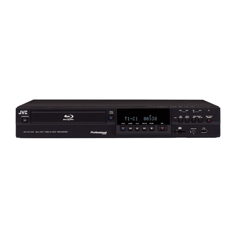
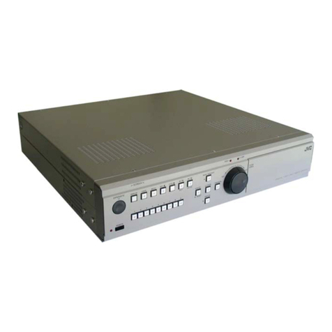
JVC VR-510U User manual

LLT0010-001A
R
DIGITAL VIDEO RECORDER
VR-510U INSTRUCTIONS
For Customer Use:
Enter below the Serial No. which is
located on the rear of cabinet. Retain this
information for future reference.
Model No. VR-510U
Serial No.
POWER
WARNING
SLEEP REC STOP PLAY STILL
TIMER CANCEL
DISPLAY
MENU
SEARCH
S
E
L
E
C
T
REV FWD
EXECUTE
SKIP/ALARM
SEARCH
REC
CLOCK RESET/ CLEAR
OPE. LOCK
ON
DIGITAL VIDEO RECORDER VR-510U

2
1. Read all of these instructions.
2. Save these instructions for later use.
3. All warnings on the product and in the operating instructions should be adhered to.
4. Unplug this appliance system from the wall outlet before cleaning. Do not use liquid cleaners or aerosol cleaners. Use a damp
cloth for cleaning.
5. Do not use attachments not recommended by the appliance manufacturer as they may cause hazards.
6. Do not use this appliance near water – for example, near a bathtub, washbowl, kitchen sink, or laundry tub, in a wet basement,
or near a swimming pool, etc.
7. Do not place this appliance on an unstable cart, stand, or table. The appliance may fall, causing serious
injury to a child or adult, and serious damage to the appliance.
Use only with a cart or stand recommended by the manufacturer, or sold with the appliance.
Wall or shelf mounting should follow the manufacturer’s instructions, and should use a mounting kit
approved by the manufacturer.
An appliance and cart combination should be moved with care. Quick stops, excessive force, and un-
even surfaces may cause the appliance and cart combination to overturn.
8. Slots and openings in the cabinet and the back or bottom are provided for ventilation, and to insure
reliable operation of the appliance and to protect it from overheating, these openings must not be blocked
or covered. The openings should never be blocked by placing the appliance on a bed, sofa, rug, or other similar surface. This
appliance should never be placed near or over a radiator or heat register. This appliance should not be placed in a built-in
installation such as a bookcase unless proper ventilation is provided.
9. This appliance should be operated only from the type of power source indicated on the marking label. If you are not sure of the
type of power supplied to your home, consult your dealer or local power company. For appliance designed to operate from
battery power, refer to the operating instructions.
10. This appliance system is equipped with a 3-wire grounding type plug (a plug having a third (grounding) pin). This plug will only
fit into a grounding-type power outlet. This is a safety feature. If you are unable to insert the plug into the outlet, contact your
electrician to replace your obsolete outlet. Do not defeat the safety purpose of the grounding plug.
11. For added protection for this product during a lightning storm, or when it is left unattended and unused for long periods of time,
unplug it from the wall outlet and disconnect the antenna or cable system. This will prevent damage to the product due to
lightning and power-line surges.
12. Do not allow anything to rest on the power cord. Do not locate this appliance where the cord will be abused by persons walking
on it.
13. Follow all warnings and instructions marked on the appliance.
14. Do not overload wall outlets and extension cords as this can result in fire or electric shock.
15. Never push objects of any kind into this appliance through cabinet slots as they may touch dangerous voltage points or short
out parts that could result in a fire or electric shock. Never spill liquid of any kind on the appliance.
16. Do not attempt to service this appliance yourself as opening or removing covers may expose you to dangerous voltage or
other hazards. Refer all servicing to qualified service personnel.
17. Unplug this appliance from the wall outlet and refer servicing to qualified service personnel under the following conditions:
a. When the power cord or plug is damaged or frayed.
b. If liquid has been spilled into the appliance.
c. If the appliance has been exposed to rain or water.
d. If the appliance does not operate normally by following the operating instructions. Adjust only those controls that are
covered by the operating instructions as improper adjustment of other controls may result in damage and will often require
extensive work by a qualified technician to restore the appliance to normal operation.
e. If the appliance has been dropped or the cabinet has been damaged.
f. When the appliance exhibits a distinct change in performance – this indicates a need for service.
18. When replacement parts are required, be sure the service technician has used replacement parts specified by the manufac-
turer that have the same characteristics as the original part. Unauthorized substitutions may result in fire, electric shock, or
other hazards.
19. Upon completion of any service or repairs to this appliance, ask the service technician to perform routine safety checks to
determine that the appliance is in safe operating condition.

3
CAUTION ATTENTION
RISK OF ELECTRIC SHOCK
DO NOT OPEN
RISQUE D’ELECTROCUTION
NE PAS OUVRIR
INFORMATION
This equipment has been tested and found to comply with the
limits for a Class B digital device, pursuant to Part 15 of the
FCC Rules. These limits are designed to provide reasonable
protection against harmful interference in a residential installa-
tion. This equipment generates, uses, and can radiate radio
frequency energy and, if not installed and used in accordance
with the instructions, may cause harmful interference to radio
communications. However, there is no guarantee that interfer-
ence will not occur in a particular installation.
If this equipment does cause harmful interference to radio or
television reception, which can be determined by turning the
equipment off and on, the user is encouraged to try to correct
the interference by one or more of the following measures:
●Reorient or relocate the receiving antenna.
●Increase the separation between the equipment and receiver.
●Connect the equipment into an outlet on a circuit different
from that to which the receiver is connected.
●Consult the dealer or an experienced radio/TV technician for
help.
CAUTION
CHANGES OR MODIFICATIONS NOT APPROVED BY JVC
COULD VOID USER’S AUTHORITY TO OPERATE THE
EQUIPMENT.
NOTE:
The rating plate (serial number plate) is on the bottom of the unit.
ATTENTION: POUR EVITER TOUT RISQUE D’ELECTROCUTION
NE PAS OUVRIR LE BOITER.
AUCUNE PIECE INTERIEURE N’EST
A REGLER PAR L’UTILISATEUR.
SE REFERER A UN AGENT QUALIFIE EN CAS DE PROBLEME.
CAUTION: TO REDUCE THE RISK OF ELECTRIC SHOCK,
DO NOT REMOVE COVER (OR BACK).
NO USER-SERVICEABLE PARTS INSIDE.
REFER SERVICING TO QUALIFIED SERVICE PERSONNEL
WARNING:
TO REDUCE THE RISK OF FIRE OR ELECTRIC
SHOCK, DO NOT EXPOSE THIS APPLIANCE TO
RAIN OR MOISTURE.
This unit should be used with 120 V AC only.
CAUTION:
To prevent electric shocks and fire hazards, DO NOT
use any other power source.
AVERTISSEMENT:
POUR EVITER LES RISQUES D’INCENDIE OU
D’ELECTROCUTION, NE PAS EXPOSER
L’APPAREIL A L’HUMIDITE OU A LA PLUIE.
Ce magnétoscope ne doit être utilisé que sur du
courant alternatif en 120 V.
ATTENTION:
Afin d’éviter tout resque d’incendie ou
d’électrocution, ne pas utiliser d’autres sources
d’alimentation électrique.
REMARQUE:
La plaque d’identification (numéro de série) se trouve sur le
panneau arrière de l’appareil.
INFORMATION (FOR CANADA)
RENSEIGNEMENT (POUR CANADA)
This Class B digital apparatus complies with Canadian ICES-
003.
Cet appareil numérique de la Class B est conforme àla
norme NMB-003 du Canada.
WARNING ON LITHIUM BATTERY
The battery used in this device may present a fire or chemical
burn hazard if mistreated. Do not recharge, disassemble, heat
above 100˚C (212˚F) or incinerate.
Replace battery with Matsushita Electric CR2032, use of
another battery may present a risk of fire or explosion.
•Dispose of used battery promptly.
•Keep away from children.
•Do not disassemble and do not dispose of in fire.
Le symbole de l’éclair àl’intérieur d’un triangle
équilatéral est destinéàalerter l’utilisateur sur la
présence d’une “tension dangereuse”non isolée dans
le boîtier du produit. Cette tension est suffisante pour
provoquer l’électrocution de personnes.
Le point d’exclamation àl’intérieur d’un triangle
équilatéral est destinéàalerter l’utilisateur sur la
présence d’opérations d’entretien importantes au sujet
desquelles des renseignements se trouvent dans le
manuel d’instructions.
*Ces symboles ne sont utilisés qu’aux Etats-Unis.
The lightning flash with arrowhead symbol, within an
equilateral triangle, is intended to alert the user to the
presence of uninsulated “dangerous voltage”within the
product’s enclosure that may be of sufficient magnitude
to constitute a risk of electric shock to persons.
The exclamation point within an equilateral triangle is
intended to alert the user to the presence of important
operating and maintenance (servicing) instructions in
the literature accompanying the appliance.
THIS DEVICE COMPLIES WITH PART 15 OF THE FCC
RULES. OPERATION IS SUBJECT TO THE FOLLOWING
TWO CONDITIONS: (1) THIS DEVICE MAY NOT CAUSE
HARMFUL INTERFERENCE, AND (2) THIS DEVICE MUST
ACCEPT ANY INTERFERENCE RECEIVED, INCLUDING
INTERFERENCE THAT MAY CAUSE UNDESIRED OPERA-
TION.
SAFETY PRECAUTIONS

4
Thank you for purchasing the JVC
VR-510U digital video recorder.
1. INTRODUCTIONS
1-1 Precautions ................................................................. 5
2. CONTROLS, CONNECTIONS AND DISPLAY
2-1 Front panel ..................................................................6
2-2 Rear panel .................................................................. 7
2-3 Display ........................................................................8
3. CONNECTIONS
3-1 Recording video signals from a camera ..................... 9
3-2 Connecting more than one camera (using an external
switcher).................................................................... 10
3-3 Connecting signal input/output terminals .................. 11
4. PREPARATION
4-1 Installing a battery ..................................................... 12
4-2 Power supply ............................................................ 12
4-3 Setting the date and time .......................................... 13
4-4 Daylight-saving time compensation .......................... 13
5. ON-SCREEN DISPLAY/MENU SWITCHES
5-1 On-screen display ..................................................... 14
5-2 Menu switches .......................................................... 15
Menu flow................................................................. 15
Jog/shuttle dial operation .......................................... 16
Display ...................................................................... 17
Setting ....................................................................... 18
5-3 Menu switch details .................................................. 19
6. RECORDING
6-1 Basic operation ......................................................... 22
Recording system
<Normal recording> <Repeat recording> ................. 22
6-2 Program timer recording ........................................... 23
Weekly timer ............................................................. 23
Timer-recording for 24 hours or more ....................... 24
Daily timer ................................................................. 25
Estimated recordable duration .................................. 26
6-3 Holiday timer recording ............................................. 27
6-4 Alarm recording......................................................... 28
Repeat recording during alarm recording ................. 28
6-5 Sensor recording ...................................................... 29
Pre-sensor recording ................................................ 29
6-6 Recording with an external activation signal ............. 30
6-7 Automatic restart of recording after power failure ..... 30
7. PLAYBACK AND SPECIAL-EFFECTS PLAYBACK
7-1 Basic operation ......................................................... 31
Playback ................................................................... 31
Simultaneous Playback mode .................................. 31
7-2 Jog/shuttle playback ................................................. 32
7-3 Skip search ............................................................... 33
Time search .............................................................. 33
Event search ............................................................. 34
Alarm search ............................................................. 34
7-4 Alarm or day/time direct search ................................. 35
8. HARD DISK CONTROL
8-1 Hard disk maintenance ............................................. 36
Scanning the disk ..................................................... 36
Formatting ................................................................. 37
9. TROUBLESHOOTING
9-1 Error indication ......................................................... 38
9-2 No error indication .................................................... 39
10. RS-232C INTERFACE
10-1 Specifications .......................................................... 40
10-2 Protocols and commands ........................................ 40
10-3 Commands .............................................................. 42
11. OTHERS
11-1 Recording time ....................................................... 47
11-2 Signal input/output terminals ................................... 48
11-3 Specifications .......................................................... 49
CONTENTS

5
1 INTRODUCTION
●Large-capacity hard disk (80 GB)
Large-capacity hard disk enables high-quality/high-capacity
recording/playback. (Can be increased up to 160 GB)
●Simultaneous recording/playback mode
You can play or back up programs even during recording.
●Instant picture search
You can access images at a specified date/time or alarm
point instantly.
●Restoring recording after power failure
When power is restored after power failure, recording
automatically re-starts in the same mode engaged before
the power failure.
●Timer recording function
Up to 8 timer recording settings can be programmed,
including daily and weekly.
●Alarm recording function
You can preset the VCR to automatically enter a specified
recording mode whenever an alarm signal is received.
●RS-232C control
JVC cannot accept liability for loss or damage to recording
that result from a malfunction of this unit or the hard drive.
Please note that it may be unlawful to use any material
recorded from television broadcast programs or pre-
recorded programs without the consent of the owner of
copyright, except in cases where the material is recorded
exclusively for personal use.
When the hard disk is replaced or the firmware is up-
graded, all recorded data on the hard disk is erased.
Characters and marks used in this text
Caution : Additional information about a specific
operation or procedure.
Memo : Information about a function or specification.
Reference : Other items or pages containing information
on the topic.
1-1 Precautions
Installation and storage
●To avoid malfunctions or damage to your recorder, do
not use or store it in places subject to the following
conditions.
•Extreme heat or cold –temperature outside the allowable
range (5˚C to 40˚C)
•High humidity –outside the allowable operating range
(30% to 80%)
•Strong magnetic fields (generated by transformers,
motors, etc.)
•Electrical waves generated by equipment such as a
transceiver or cellular phone
•Dust and soil
•Vibrations
•Condensation
Handling
To prevent unit from overheating, do not place it anything
on top of any other equipment or place other equipment on
top of it.
This unit should only be operated when it is in a horizontal
(flat) position.
Avoid violent shocks to the unit.
Do not move this unit when the power is ON. This could
cause it to malfunction.
To avoid a malfunction, do not place anything heavy such
as a TV monitor on this unit.
To clean this unit, wipe it gently with a soft cloth.
Do not use chemical solvents such as thinner or benzene
to clean this unit. Doing so could damage the surface. To
remove any excessive dirt, wipe the unit with a cloth dipped
in detergent and then wipe it with a dry cloth.
Transportation
Do not apply a shock to this unit during transportation. Do
not move this unit during recording or playback.
Energy saving
When the unit is not going to be used for a long time, turn
the power off to avoid unnecessary power consumption.
Hard disk
The hard disk is a consumable item. Replacement is
recommended after 30,000 hours of use (if used in a 25˚C
environment). For information on maintenance planning
and costs, consult your nearest JVC dealer.
Major features

6
2 CONTROLS, CONNECTIONS AND DISPLAY
2-1 Front panel
1
[LITHIUM BATTERY] battery box for memory backup
Install a memory backup battery. When replacing the battery with
a new one, be sure to set the date/time again.
Reference: “4-1 Installing a battery”on page 12.
2
[POWER] indicator
When the [POWER] switch is turned ON, this indicator lights.
3
[DISPLAY PANEL]
Shows the operation status or setting details.
Reference: “2-3 Display”on page 8.
4
[TIMER] button
After programming the timer, press this button to engage the
Standby mode.
Reference: “6-2 Program timer recording”on page 23.
5
[CANCEL] button
•When a line is selected on the [PROGRAM TIMER] or
[HOLIDAY SET] screen, press this button to clear it.
•When an alarm or warning occurs, press this button to stop the
buzzer.
Reference: “6-2 Program timer recording”on page 26 and “6-4
Alarm recording”on page 28
6
[MENU] button
Press this button in the Stop mode to display the main menu
setting screen.
* The menu cannot be displayed when the
6
[TIMER] indicator
(see page 8) is on or during recording/playback.
7
[SEARCH] button
Press to display the search menu for alarm search or time/date
search. Pressing this button again restores the normal screen.
Reference: “7-4 Alarm or day/time direct search”on page 35.
8
[DISPLAY] display panel switching button
Each time this button is pressed, the display changes in order from
CLOCK to DATE to REMAIN to REC QUALITY-REC SPEED.
•Press [DISPLAY] button in any mode except Record for about 2
seconds. The recording setting display is displayed, allowing
you to set recording quality/number of frames.
9
Jog dial
In the Play or Still mode, use this dial for frame-by-frame
playback.
Reference: “7-2 Jog/shuttle playback”on page 32.
With the menu/search screen, use this dial to set the item or
value.
Reference: “Jog/shuttle dial operation”on page 16.
0
Shuttle search dial
Turn to vary the playback speed in the Play or Still mode.
Reference: “7-2 Jog/shuttle playback”on page 32.
With the menu/search screen, use this dial to set the item or
value.
Reference: “Jog/shuttle dial operation”on page 16.
!
[REC] indicator
Lights when recording on the hard disk.
Blinks during alarm/sensor recording.
Goes out during recording if you set <REC TALLY> of <FRONT
DISPLAY> to “OFF”.
Reference: “5-3 Menu switch details”on page 19.
@
[CLOCK RESET/CLEAR] button
In the Stop mode, press this button together with the [STOP]
button to reset the second value on the internal clock.
•With 29 seconds or less, the minute value stays the same and
the second value is reset to 00.
•With 30 seconds or more, the minute value is increased by 1
and the second value is reset to 00.
Pressing this button stops recording during alarm/sensor
recording.
When the alarm list screen or power-off list screen is displayed,
pressing this button clears the list.
Reference: “7-4 Alarm or day/time direct search”on page 35.
Use this button to cancel the [AUTO SCAN DISK] function.
Reference: “8-1 Hard disk maintenance”on page 36.
#
[OPE.LOCK] operation lock key
Set to “ON”position with the provided key to lock switch
operation.
Security levels can be selected with menu switch <OPERATION
LOCK MODE>.
●ALL: Locks all switches.
●REC STOP: Prevents recording from being stopped when the
&
[STOP] button is pressed.
* Set to “ALL”for timer recording.
Reference: “5-3 Menu switch details”on page 19.
$
[SKIP/ALARM SEARCH·EXECUTE] SKIP SEARCH·EXECUTE
button
Skip search
In the Stop mode, press this button to go to the start or end of a
recording of the hard disk.
In the Play mode, press this button to start skip search.
There are three types of skip search:
●Time search: Goes to the point a specified time from the
current point.
●Event search: Goes to the start of an event recording.
●Alarm search: Goes to the start of an alarm recording.
Reference: “7-3 Skip search”on page 33
EXECUTE button
Use this button to execute alarm direct search, day/time direct
search or “disk scan”/ “quick format”.
Reference: “7-4 Alarm or day/time direct search”on page 35 and
“8-1 Hard disk maintenance”on page 36
%
[STILL] button
In the Play mode, press this button to engage the Still mode.
^
[PLAY] button
Press this button to start playback.
●In the Stop mode: Playback starts at the position where
playback was last stopped.
* Just after the power is turned ON, playback starts from a point
about 5 seconds before the end point of the last recording.
●In the Record mode: Simultaneous Playback mode is
engaged.
Reference: “Simultaneous Playback mode”on page 31.
7 8
POWER
WARNING
SLEEP REC STOP PLAY STILL
TIMER CANCEL
DISPLAY
MENU
SEARCH
S
E
L
E
C
T
REV FWD
EXECUTE
SKIP/ALARM
SEARCH
REC
CLOCK RESET/ CLEAR
OPE. LOCK
ON
DIGITAL VIDEO RECORDER VR-510U
12
910 11
456
13
15161718
1920 14
1
23
* Behind
the cover
7
2 CONTROLS, CONNECTIONS AND DISPLAY (contd.)
2-2 Rear panel
&
[STOP] button
Press this button to stop operation. In the Simultaneous
Playback mode, press this button to stop playback and engage
the normal recording mode.
*
[REC] button
Press in the Stop mode to start recording. The recording mode
can be set with the menu switch.
Reference: “6-1 Basic operation”on page 22.
(
[SLEEP] button
Before turning the power OFF, press this button to stop the
rotation of the hard disk.
)
[SYSTEM RESET] button
This button is used for servicing. Normally, you do not need to
use this button.
q
[POWER] switch
Turns power ON/OFF.
* Before turning the power OFF, press the
(
[SLEEP] button to
stop the rotation of the hard disk.
w
[AC IN] socket
Connect to an AC 120 V outlet using the provided power cable.
e
Signal input/output terminal
CAM SW OUT
Outputs camera switch timing control signals when this unit is
connected to a frame switcher.
Reference: "3-2 Connecting more than one camera (using an
external switcher)" on page 10.
ALARM IN 1
Accepts signals to start alarm or sensor recording.
ALARM RESET
Accepts signals to stop recording during alarm or sensor
recording.
CLOCK RESET IN
Connect to a master clock or the [CLOCK RESET
OUT] terminal of another device. When a clock reset
signal is input, this unit can be set to the master clock
or the other device’s clock.
When the clock reset signal is input, the clock second
value is reset: .
●With 29 seconds or less, the minute value stays the same
and the second value is reset to 00.
●With 30 seconds or more, the minute value is increased by 1
and the second value is reset to 00.
CLOCK RESET OUT
Outputs a clock reset signal when the internal clock is 00:00
or 12:00.
EXT REC IN
Recording is automatically activated by an external signal
when menu switch <REC MODE> of <EXT MODE> is set to
“TRIG”or “MANUAL”.
Reference: “5-3 Menu switch details”on page 20.
HDD FULL OUT
Outputs a signal during recording when the hard disk’s
available space is 0% except in the following cases.
●Menu switch <HDD FULL OUT> set to “OFF”
●Menu switch <REPEAT REC> set to “ALL”
Reference: “5-3 Menu switch details”on page 20.
r
[AUDIO OUT] audio output connector
Outputs recorded audio during playback.
In the Record or Stop mode, outputs the input audio signal.
Audio is not output in the following cases.
●When playing back signals recorded with menu switch <REC
SPEED> set to “1/5”or “1/10”
●In the Frame-by-Frame Playback, Still or Search mode
●When playing back signals recorded with menu switch <AUDIO
REC> set to “OFF”
●When the menu is displayed
t
[MONITOR OUT] monitor output connector
Outputs video signals recorded on the hard disk in the Play
mode. In the Record mode, outputs video input signals from the
camera or frame switcher connected to the [CAMERA IN]
connector.
The picture signal from the [CAMERA IN] connector is output
through the [MONITOR OUT] connector even when the power is
turned OFF.
y
[CAMERA IN] camera input connector
Connect to a camera.
u
[AUDIO IN] audio input connector
Connect to the audio output connector of the audio source
device.
i
[RS-232C] remote connector
Connect a personal computer or compatible control unit for
external remote operation.
Reference: “10. RS-232C INTERFACE”on page 40.
CAMERA IN
MONITOR OUT
1
1
2
12
AUDIO
IN
AUDIO
OUT
RS-232C
POWER
SIGNAL GND
CAM SW
OUT
ALARM
IN1
SPARE SPARE
SPARE
HDD
FULL OUT
ALARM
RESET
CLOCK
RESET IN
CLOCK
RESET OUT
EXT
REC IN
COM COM
ON OFF
IO
AC IN 120 V
50 Hz / 60 Hz
26 27 28 21
222325 24

8
2 CONTROLS, CONNECTIONS AND DISPLAY (contd.)
2-3 Display
1
WARNING indication
Blinks when there is a problem with input signals, fan
motor or hard disk, as well as when the battery is low.
Reference: “9-1 Error indication”on page 38.
2
Operation mode indication
3
SENSOR ON indication
Lights when menu switch <REC MODE> of <ALARM/
SENSOR MODE> is set to “SENSOR”.
Reference: “6-5 Sensor recording”on page 29.
4
[MENU, SEARCH SET] indication
Lights during menu operation or search setting.
5
[REPEAT REC] indication
Lights when repeat recording is set.
Reference: "5-3 Menu switch details" on page 20 and
“6-1 Basic operation”on page 22.
6
[TIMER] indication
Lights in the Timer Record Standby mode or during timer
recording.
Reference: “6-2 Program timer recording”on page 23.
7
[REMAIN] indication
Lights when the remaining time is displayed (refer to
8
[DISPLAY] button on page 6 for more details).
8
Counter and function display
The counter is displayed in the Play or Record mode.
Pressing the
8
[DISPLAY] button on the front panel (see
page 6) switches the display consecutively through
CLOCK, DAY, REMAIN and REC QUALITY•REC SPEED.
CLOCK display
Displays the time.
During playback, the approximate time of the recording is
displayed. Accuracy of the display time varies depending
on the recording speed.
Reference: “4-3 Setting the date and time”on page 13.
DAY display
REMAIN TIME display
Displays the remaining recording time.
Memo:
•If REPEAT REC is set,
5
[REPEAT REC] and “RE-
PEAT”are displayed. Remaining time is not displayed.
REC QUALITY·REC SPEED display
* The 1/2, 1/5 and 1/10 frame are shown as below.
1/2 frame:
1/5 frame:
1/10 frame:
Reference: DVR MODE in “5-3 Menu switch details”on
page 19.
REC SPEED
Remaining time
VN
S
12 4 5 6 8
7
3
Play Still
Simultaneous play
Simultaneous still
Blinks alternately
Record
Simultaneous search or
simultaneous Slow Motion play
Search or Slow Motion play
VN
S
Switching with 1-second interval.
VN
S
VN
S
e.g.: Jan. 1, 2001 is displayed.
VN
S
Lights
VN
S
REC QUALITY
SLEEP display
When the [SLEEP] button is pressed, the hard disk
stops rotating and “SLEEP”is displayed.
* When the Record mode is engaged from the Sleep mode,
the hard disk has to warm up before recording can start. No
images will be recorded during this period.
VN
S
* Dotted line mark blinks
VN
S

9
3 CONNECTIONS
3-1 Recording video signals from a camera
This section describes how to connect a camera and record camera signals. When more than one camera is connected, the
cameras must be synchronized. Multi-camera connections are discussed in the next section.
To AC 120 V, 50 Hz/
60 Hz
Connecting a camera
1. Connect the [MONITOR OUT] and [AUDIO OUT] connectors to the monitor’s video and audio connectors.
2. Connect [CAMERA IN] connector to the video camera’s video output connector.
3. To record sound, connect a microphone amplifier to the [AUDIO IN] connector.
4. To record an alarm, connect the alarm sensor to the [ALARM IN 1] and [COM] signal input/output terminals.
5. After all connections are complete, connect the power cable to the [AC IN] socket and connect the plug to an AC 120 V outlet.
6. Turn ON all connected equipment, then turn the [POWER] switch on the rear panel to ON.
Menu switch setting
Example of settings when using an alarm sensor and recording audio.
DVR MODE
[REC QUALITY] set to “N”
[REC SPEED] set to “30”
[AUDIO REC] set to “ON”
ALARM/SENSOR MODE
[REC MODE] set to “ALARM”
Reference: “5-3 Menu switch details”on page 19.
Caution:
●Before connecting or disconnecting any equipment,
turn the power of all connected equipment OFF.
CAMERA IN
MONITOR OUT
1
1
2
12
AUDIO
IN
AUDIO
OUT
RS-232C
POWER
SIGNAL GND
CAM SW
OUT
ALARM
IN1
SPARE
SPARE
SPARE HDD
FULL OUT
ALARM
RESET
CLOCK
RESET IN
CLOCK
RESET OUT
EXT
REC IN
COM COM
ON OFF
IO
AC IN 120 V
50 Hz / 60 Hz
Video camera
Amplifier
Microphone
Provided
power cable
Monitor Alarm sensor
ALARM IN
COM

10
3 CONNECTIONS (contd.)
3-2 Connecting more than one camera (using an external
switcher)
When an external switcher is connected to the [CAMERA IN] connector of this unit, images from multiple cameras can be
recorded. Select the camera image with the switcher.
●For a connectable multiplexer (switcher), consult your JVC dealer.
Connection procedures
1.Connect the video output connector of the frame switcher to the video input connector of the monitor.
2.Connect the camera to the [CAMERA IN] connector of the frame switcher.
* For camera connections, refer to the frame switcher’s instructions.
3.Connect the frame switcher’s [VTR OUT] connector to the [CAMERA IN] connector of this unit.
4.Connect the [MONITOR OUT] connector of this unit to the frame switcher’s [VTR IN] connector.
5.Connect the alarm sensor to the frame switcher.
6.Connect the frame switcher’s [VTR TRIGGER] and [ALARM OUT] signal input/output terminals to the [CAM SW OUT] and
[ALARM IN 1] terminals of this unit.
7.After all connections are complete, connect the power cable to the [AC IN] socket and connect the plug to an AC 120 V outlet.
8.Turn ON all connected equipment, then turn the [POWER] switch on the rear panel to ON.
Caution:
●Before connecting or disconnecting any equipment,
turn the power of all connected equipment OFF.
●When a field switcher is used, picture quality will be
degraded if [REC QUALITY] is set to "H". In some
cases, the specified camera may not be used or the
playback picture may move up and down.
●As the camera switching signal is recorded, the picture
on the lower section of the monitor screen may be
missing. To record the external switcher’s on-screen
display, set the display to the upper section of the screen.
Memo:
●Select the camera with the switcher.
●The monitor picture may not be switched during jog/
shuttle operation and skip search operation. This is
because the playback camera number is different from
the camera number selected with the switcher. To
display the picture from the selected camera on the
monitor, press the [PLAY] button.
CAMERA IN
MONITOR OUT
1
1
2
12
AUDIO
IN
AUDIO
OUT
RS-232C
POWER
SIGNAL GND
CAM SW
OUT
ALARM
IN1
SPARE SPARE
SPARE
HDD
FULL OUT
ALARM
RESET
CLOCK
RESET IN
CLOCK
RESET OUT
EXT
REC IN
COM COM
ON OFF
IO
AC IN 120 V
50 Hz / 60 Hz
Example of settings when alarm recording is performed
using an external switcher.
DVR MODE
[REC QUALITY] set to “N”
[EXT SWITCHER] set to “ON”
ALARM/SENSOR MODE
[REC MODE] set to “ALARM”
[REC DURATION] set to “MANUAL”when the alarm
time is set with the switcher
This unit continues recording for about 5 seconds
after the alarm duration set with the switcher has
passed.
Reference: “5-3 Menu switch details”on page 19.
Menu switch setting
Video camera
Video camera
Video camera
Video camera
Switcher
To AC 120 V,
50 Hz/60 Hz
Provided
power cable
Monitor
Alarm sensor
ALARM IN
VTR TRIGGER IN
CAM SW OUT
ALARM OUT
COM
COM
COM ALARM IN
VTR IN
VTR OUT

11
COM COM
CLOCK
RESET OUT
CLOCK
RESET IN
COM
CLOCK
RESET IN
COM
EXT REC
IN
COM
CLOCK
RESET IN
3 CONNECTIONS (contd.)
3-3 Connecting signal input/output terminals
[CAM SW OUT] camera switching signal
output terminal
To control the camera switching timing from this unit.
[ALARM RESET] alarm signal reset input
terminal
To stop alarm recording when a signal is received during
alarm recording.
[CLOCK RESET IN] clock reset input terminal
To set the clock to the master clock or other device’s clock
using a signal from an external device.
[EXT REC IN] external recording control signal
input terminal
Recording can be started, stopped or controlled with an
external signal.
Switch
External
master
clock
External control
device
Starts alarm or sensor recording when a signal is received.
[HDD FULL OUT] HDD full-output terminal
Outputs a signal during recording when the hard disk is full.
* Signal output is possible only when menu switch <HDD
FULL OUT> is set to “ON”and <REPEAT REC> is not set
to “OFF”.
[CLOCK RESET OUT] clock reset terminal
Outputs a clock reset signal. It is possible to set the clock of
the digital video recorders following this unit to that of this
unit in second unit.
[ALARM IN] alarm signal input terminal
Last digital video
recorder
External interface specifications example
●Use each device rated for using situation.
Control signal
COM
CAM SW
OUT
Frame switcher’s
camera switching signal
input
COM
Vcc: 5 V-12 V
Vcc
ALARM
RESET
ALARM
IN COM
Frame switcher/alarm sensor’s
alarm output terminal
COM
HDD FULL
OUT
External
interface
This unit
Second digital
video recorder
GND
Power supply
(Lamp, etc.)
Relay
HDD full lamp
Reference: "3-2 Connecting more than one camera (using an
external switcher)" on page 10.

12
4 PREPARATION
4-1 Installing a battery
1. Turn the [POWER] switch OFF.
2. Open the battery cover.
While pushing down the pawl in the upper section of the
battery cover, pull it towards you to open the cover.
3. Install a battery.
Install the provided battery (CR2032) with the + side
facing you.
4. Close the battery cover.
Close it until the pawl is locked firmly.
Caution:
●When the power is supplied, do not replace the battery.
Otherwise, a malfunction may occur.
●Replace the battery with a CR2032 type battery. Using
any other type of battery may present a risk of fire or
explosion.
Memo:
●When you replace the battery, be sure to set the date
and time again.
Reference: “4-3 Setting the date and time”on page 13.
●After replacing the battery, be sure to program the
program timer again because the programs are reset.
●When “LOW BATTERY”is displayed, check the battery
again.
4-2 Power supply
[AC IN] socket
1. Connect the power cable.
Connect the provided power cable to an AC 120 V outlet.
2. Press the [POWER] switch to ON.
The system check starts for this unit and “SYSTEM
LOADING ...”is displayed on the monitor.
“LoAd--”blinks on the display panel.
Caution:
●After all other equipment connections are complete,
turn the power of this unit ON.
Memo:
●All operation functions are disabled during system
check. Wait until “SYSTEM LOADING ...”goes out.
POWER
WARNING
SLEEP REC STOP PLAY STILL
TIMER CANCEL
DISPLAY
MENU
SEARCH
S
E
L
E
C
T
REV FWD
EXECUTE
SKIP/ALARM
SEARCH
REC
CLOCK RESET/ CLEAR
OPE. LOCK
ON
DIGITAL VIDEO RECORDER VR-510U
2.
3.
CAMERA IN
MONITOR OUT
1
1
2
12
AUDIO
IN
AUDIO
OUT
RS-232C
POWER
SIGNAL GND
CAM SW
OUT
ALARM
IN1
SPARE SPARE
SPARE
HDD
FULL OUT
ALARM
RESET
CLOCK
RESET IN
CLOCK
RESET OUT
EXT
REC IN
COM COM
ON OFF
IO
AC IN 120 V
50 Hz / 60 Hz
[POWER] switch
VN
S

13
OGJ
4-3 Setting the date and time
4 PREPARATION (contd.)
1. Turn the power ON.
Check the connections and press the [POWER] switch
ON.
2. Display the main menu.
Press the [MENU] button to display the main menu
screen.
Refer to “Jog/shuttle dial operation”on page 16 and set
the jog dial function with the shuttle dial operation.
3. Display the [CLOCK SET] screen.
Set the cursor on [CLOCK SET] with [JOG ]. Turn the
shuttle dial to display the [CLOCK SET] screen.
4. Set the month.
Set “month”with [JOG –+].
5. Set the day.
Set the blinking cursor on “D”with [JOG p[] and set
the day with [JOG –+].
6. Set the year, hour and minute.
Repeat the procedure for step 5 for setting.
7. Enter.
When all settings are complete, press the [MENU] button
twice to restore the normal screen.
Note:
●If the date is changed when there is recorded data on
the hard disk, make sure the recording date and time
do not overlap.
Otherwise, playback operation, skip search and direct
search may not function correctly.
Characters
selected with
the cursor are
highlighted.
[MENU] button
Jog dial
Shuttle dial
f
MENU
SEARCH
S
E
L
E
C
T
REV FWD
EXECUTE
SKIP/ALARM
SEARCH
3.
[CLOCK S ET]
DAYL GHT SAVING OFFI
MDY H M
1 1 2001 0:00
JOG
Blinking
[CLOCK S ET]
DAYL GHT SAVING OFFI
MDY H M
1 1 2001 0:00
JOG
Blinking
4-4 Daylight-saving compensation
Use the <DAYLIGHT SAVING> menu switch on the CLOCK
SET setting screen to turn the Daylight Saving mode ON or
OFF.
When <DAYLIGHT SAVING> is “ON”, the set time is
advanced one hour.
•When setting the time, make sure the <DAYLIGHT
SAVING> switch is “OFF”.
When the unit is shipped, this switch is set to “OFF”.
•Clock setting is not possible during timer recording.
During daylight-saving time Standard time
1. Set the time one hour behind the actual time.
2. After setting the time, set the <DAYLIGHT SAVING>
switch to “ON”.
•The time advances one hour.
3. At the end of the daylight-saving time season, set the
<DAYLIGHT SAVING> switch to “OFF”.
•The standard time is displayed.
1. Set the clock to the actual time.
2. When the daylight-saving season starts, set the <DAY-
LIGHT SAVING> menu switch to “ON”.
•The display time advances one hour.
4.
5.

14
5 ON-SCREEN DISPLAY/MENU SWITCHES
Date, time, number of alarms and remaining hard disk capacity can be displayed on-screen. Date and time data can be
recorded together with the video signals by setting the <TIME DATE REC> menu switch to “ON”.
5-1 On-screen display
Connect the monitor’s video signal input connector to the
VR-510U’s [MONITOR OUT] connector.
1. Turn ON this unit and the monitor.
●When a signal is input to the video input connector, on-
screen data is superimposed on the picture.
●If no signal is input, on-screen data is superimposed on
a black screen.
To change the position of the on-screen
display
Set with menu switch <ON SCREEN POSITION>.
Reference: “5-3 Menu switch details”on page 19.
To select the contents of the on-screen
display
Set on the [ON SCREEN MODE] screen.
Set the items you want to display to “ON”.
If you do not want to display an item, set it to “OFF”.
* For menu switch setting, refer to “Setting”in “5-2 Menu
switches”on page 18.
To record the on-screen display
Set menu switch <TIME DATE REC>, <DAY> and
<TIME> to “ON”.
* If <DAY> and <TIME> are set to “OFF”, the on-screen
display will not be recorded even if <TIME DATE REC> is
set to “ON”.
Preparation
POWER
WARNING
SLEEP REC STOP PLAY STILL
TIMER CANCEL
DISPLAY
MENU
SEARCH
S
E
L
E
C
T
REV FWD
EXECUTE
SKIP/ALARM
SEARCH
REC
CLOCK RESET/ CLEAR
OPE. LOCK
ON
DIGITAL VIDEO RECORDER VR-510U
[MENU] button
Jog dial
Shuttle dial
000100
: :
113 10
000056 70
%
A
MON
L
AL
<On-screen display>
Month/day/year/
day of week
Time (24-hour)
Number of alarms*
Hard disk remaining
capacity
* “SN-***”is displayed in the sensor recording mode.
AL
000100
: :
113 10
000056 70
%
A
MON
L
AL
000056 70
%
AL
000100
: :
113 10MON
Upper
right
Upper
left
1
ON
SENS RO
INDI ACTION
[ONSCREEN
ONSCREEN POS I T I O
O
NLU
U
P
MODE ]
[FRONT DISPLAY]
1.
REC TALLY
1.
ALARM
2.
ALARM C NT
4.
DAY NO
2.
TIME NO
NO
REC R MEAIN
5. NO
AL SE SNDETMARK
6. NO
3.
WAR NIGN
7. NO
NO
JOG
Display items
[On-screen position]
AL/SENS DET
MARK

15
5 ON-SCREEN DISPLAY/MENU SWITCHES (contd.)
5-2 Menu switches
Main menu screen
Menu flow
[ENU]M
CLOCK SET
CNSCR
ALARM
EEN
BUZZER
HOLI DAY SET
PROGRAM T I MER
SYSTEM L I ST
DVRMODE
EXTMODE
SENSOR MODE
F.DI SP MODE
OGJ¥
[CLOCK S E T]
DAYL GHT SAVING OFFI
MDY H M
112001 0:00
JOG
1
ON
SENS RO
INDI ACTION
[ONSCREEN
ONSCREEN POS I T I O
O
NLU
U
P
MODE ]
[FRONT DISPLAY]
1.
REC TALLY
1.
ALARM
2.
ALARM C NT
4.
DAY NO
2.
TIME NO
NO
REC R MEAIN
5. NO
AL SE SNDETMARK
6. NO
3.
WAR NIGN
7. NO
NO
JOG
NORM
27H
30
REPEAT REC
1HOUR
O PERATE LO CK MODE
OFF
ALL
[DVR MODE]
1. REC QUALI TY
ON
3. AUDIOREC
ON
4. POW
ERON REC
METI
5. SEA
RCH BUTTON
6.
7.
TIME D TAEREC ON
ON
8.
9.
. EXT ISW TCHER10
SK I PRADU T I O N
2. REC SPEED
REC T IME
JOG
[EXT MODE]
REC DUR
ATI ON 10SEC
1. REC MODE OFF
1. REC MODE OFF
2. REC DURAT ONI
2. HDD FULL OUT OFF
[ALARM SENSOR MODE]
180SEC
3. PRES ENSO
R
4. PRES ENSO
R
RECOFF
OGJ
[BUZZER ]
1. HDD END ON
ON
2. ALAR
M
ON
3. WARN NGI
SENSOR
OGJ
[PRO
GRAM T I M E R ]
PRG
MODES T AR T E ND
: :
SUN
SUN
: :
MON
MON
: :
TUE
TUE
: :
WE D
: :
THU
THU
: :
FR I
FR I
: :
SAT
SAT
:
WE D
:
DAY
DAI LY SET
JOG
[HO L ID
AY SET]
PRG
MODES T AR T E ND
: :
JOG
1:
3:
5:
7:
9:
11 :
13 :
15 :
2:
4:
6:
8:
10 :
12 :
14 :
16 :
[SYSTEM ]
[LIST]
UTI L I T YBG08]
OGJ
[
HOUR METER
POWER LOSS LIST
[HOUR M TER]E
[POWER OSS LI ST]L
HDD RUN T I ME 00H0000
PL ::
PL ::
PL ::
PL ::
[UT I L I T ]Y
1. AUTO SC NDI SKA
SC ND I SKA
OFF
OFF
OFF
STD
2. MANUAL
3. QU I CK ERAS E
OGJ
CURRENT FORMAT

16
5 ON-SCREEN DISPLAY/MENU SWITCHES (contd.)
5-2 Menu switches (contd.)
Jog/shuttle dial operation
Use the jog/shuttle dial to set the menu or search menu items.
Turn the shuttle dial to the right or left so that it passes the
SELECT position.
Main menu or search menu screen
•Turning the shuttle dial displays the selected main menu
or search menu screen for menu switch setting.
Menu switch setting screen
•Each time the shuttle is turned, the jog operation function
is switched.
Shuttle dial operation
1. JOG function
Turn the jog dial to move the cursor or blinking mark up
and down.
2. JOG p[ function
Turn the jog dial to move the cursor or blinking mark to
the right and left.
3. JOG –+ function
Turn the jog dial to change the set value.
Memo:
●For setting procedure, refer to the page 17 and on.
S
E
L
E
C
T
REV FWD
Jog dial
Shuttle dial
f
JOG
1. Menu or search screen
Turn the shuttle dial.
2. Menu or search screen
Turn the shuttle dial.
3. Menu or search screen
Turn the shuttle dial.
JOG p[
f
JOG - +
Jog dial operation
OGJ
+
OGJJOG

17
[ENU]M
CLOCK SET
CNSCR
ALARM
EEN
BUZZER
DVRMODE
EXTMODE
SENSOR MODE
F.DI SP MODE
OGJ
HOLI DAY SET
PROGRAM T I MER
SYSTEM L I ST
POWER
WARNING
SLEEP REC STOP PLAY STILL
TIMER CANCEL
DISPLAY
MENU
SEARCH
S
E
L
E
C
T
REV FWD
EXECUTE
SKIP/ALARM
SEARCH
REC
CLOCK RESET/ CLEAR
OPE. LOCK
ON
DIGITAL VIDEO RECORDER VR-510U
5 ON-SCREEN DISPLAY/MENU SWITCHES (contd.)
5-2 Menu switches (contd.)
Display
Connect the [MONITOR OUT] connector to the
monitor’s video input connector.
1. Turn this unit and the monitor ON.
2. Display the main menu screen.
Press the [MENU] button to display the main menu
screen on the monitor.
Switch the jog dial function with the shuttle dial as
described in “Jog/shuttle dial operation”on page 16.
3. Select the item to be set.
Turn the Jog dial (in JOG mode) to move the cursor
over the desired item.
4. Display the menu switch setting screen.
Turn the shuttle dial to display the menu switch setting
screen for the selected item.
5. Return to the main menu screen.
To restore the main menu screen, press the [MENU]
button. Press it again to restore the normal screen.
<Main menu screen>
Main menu item details
Clock setting
To display the date and clock setting screen. Before
using this unit for the first time, you must set the date
and time.
Reference: “4-3 Setting the date and time”on page 13.
On-screen display setting
To set items to be displayed on screen.
Front display setting
These menu switches are used to set indicator lighting
preferences.
DVR mode setting
These menu switches are used to set operation prefer-
ences including recording picture quality and repeat
recording/playback.
External recording setting
These menu switches are used to specify settings for the
externally activated automatic recording and switching
signal output ON/OFF when the hard disk is full.
Alarm/sensor recording setting
These menu switches are used to set alarm/sensor
recording preferences.
Buzzer setting
These menu switches switch the alarm/sensor buzzer
and the full hard disk warning buzzer ON/OFF.
Program timer setting
To display the program setting screen for timer recording.
Holiday setting
To display the timer recording program setting screen for
a specified date such as a holiday.
System setting
These menu switches are used to set maintenance
preferences such as disk scanning and formatting.
[MENU] button
Jog dial
Shuttle search dial
The characters
selected with the
cursor are
highlighted.
f
[DISPLAY] button

18
5 ON-SCREEN DISPLAY/MENU SWITCHES (contd.)
5-2 Menu switches (contd.)
Setting
Connect the [MONITOR OUT] connector to the
monitor’s video input connector.
1. Turn this unit and the monitor ON.
Data is displayed on-screen.
2. Display the main menu screen.
Press the [MENU] button to display the main menu
screen.
Switch the jog dial function with the shuttle dial as
described in “Jog/shuttle dial operation”on page 16.
3. Select the item to be set.
Turn the Jog dial [JOG ] to move the cursor over the
desired item.
4. Display the menu switch setting screen.
Turn the shuttle dial to display the menu switch setting
screen for the selected item.
5. Select the menu switch to be set.
Select the menu switch item to be set with [JOG ].
6. Change the set value.
Change the set value with [JOG –+].
* To change the other menu switches, press the [MENU]
button to return to the main menu screen.
7. Quit the menu switch setting.
When all settings are complete, press the [MENU] button
twice. The normal screen is restored.
[ENU]M
CLOCK SET
CNSCR
ALARM
EEN
BUZZER
DVRMODE
EXTMODE
SENSOR MODE
F.DI SP MODE
OGJ
HOLI DAY SET
PROGRAM T I MER
SYSTEM L I ST
NORM
27H
30
REPEAT REC
1HOUR
O PERATE LO CK MODE
OFF
ALL
[DVR MODE]
1. REC QUALI TY
ON
3. AUDIOREC
ON
4. POW
ERON REC
METI
5. SEA
RCH BUTTO N
6.
7.
TIME D TAEREC ON
ON
8.
9.
. EXT ISW TCHER10
SK I PRADU T I O N
2. REC SPEED
REC T IME
JOG
NORM
27H
30
REPEAT REC
1HOUR
O PERATE LO CK MODE
OFF
ALL
[DVR MODE]
1. REC QUALI TY
ON
3. AUDIOREC
ON
4. POW
ERON REC
METI
5. SEA
RCH BUTTO N
6.
7.
TIME D TAEREC ON
ON
8.
9.
. EXT ISW TCHER10
SK I PRADU T I O N
2. REC SPEED
REC T IME
JOG
The characters
selected with
the cursor are
highlighted.
f
Select with JOG .
Select with
JOG –+.
<Main menu screen>
f
f
3.
5.
6.
Set <REC QUALITY> and <REC SPEED> on the
display panel.
1. Set the recording set display.
Press the [DISPLAY] button for about 2 seconds (not
available during recording).
The <REC SPEED> setting section blinks slowly.
Switch the jog dial function with the shuttle dial as
described in “Jog/shuttle dial operation”on page 16.
2. Set <REC SPEED>.
When the shuttle dial is turned, the <REC SPEED>
setting section blinks rapidly. Turn the jog dial to set the
required recording speed.
3. Set <REC QUALITY>.
Turn the shuttle dial so that the <REC SPEED> setting
section blinks slowly. Turn the jog dial so that the <REC
QUALITY> setting section blinks slowly. Repeat the
procedure in Step 2 to set the picture quality.
4. End setting.
Press the [DISPLAY] button to restore the normal display.
* If the Record mode is engaged during setting, the
normal display is automatically restored (ALARM/
SENSOR MODE, etc.).
VN
S
VN
S
VN
S
1.
2.
3.
REC QUALITY REC SPEED
Set when this indicator
blinks rapidly.
Set when this indicator
blinks rapidly.

19
5 ON-SCREEN DISPLAY/MENU SWITCHES (contd.)
5-3 Menu switch details
The setting in [ ] is the factory setting.
Setting item Menu switch Setting value Description
ON SCREEN ON SCREEN [UP-L] Sets the on-screen display position.
MODE POSITION UP-R
LOW-L
LOW-R
DAY [ON] Sets the on-screen day/month/year display.
OFF ON : Displayed.
OFF: Not displayed.
TIME [ON] Sets on-screen clock display
OFF ON : Displayed.
OFF: Not displayed.
ALARM COUNT [ON] Sets the on-screen alarm/sensor number display.
OFF ON : Displayed.
OFF: Not displayed.
REC REMAIN [ON] Sets the on-screen remaining hard disk capacity display.
OFF ON : Displays the remaining capacity (does not display it
when the repeat recording is set to “ON”).
OFF: Does not display the remaining capacity.
AL/SENS DET [ON] Sets whether or not the “AL”mark is displayed on screen
MARK OFF during alarm/sensor recording.
ON : Displayed.
OFF: Not displayed.
WARNING [ON] Sets whether or not warnings are displayed on screen when
OFF an abnormality occurs.
ON : Displayed.
OFF: Not displayed.
FRONT DISPLAY REC TALLY [ON] Sets whether or not the recording indicator on the front panel
OFF lights during recording.
ON : Indicator lights.
OFF: Indicator does not light.
ALARM/SENSOR [ON1] Sets whether or not the recording indicator blinks when
INDICATION ON2 an alarm/sensor signal is input.
OFF ON1 : Indicator blinks during alarm/sensor recording.
ON2 : Indicator blinks when alarm/sensor recording is com
pleted (this mode can be released with the [CANCEL]
button).
* ON1 and ON2 are effective only when menu switch <REC
TALLY> is set to “ON”.
OFF: The indicator lights during alarm/sensor recording.
DVR MODE REC QUALITY HIGH Sets the recording picture quality.
[NORM] HIGH : High-quality recording.
BASIC NORM : Normal-quality recording.
LOW BASIC : Middle-quality recording.
LOW : Low-quality recording.
Reference: “11-1 Recording time”on page 47.
REC SPEED [30] Sets the number of frames to be recorded. The displayed
15 value shows the number of frames recorded in one second.
10 <REC TIME> shows the available recording time on the hard
5 disk. The amount of recording time available depends on the
3 settings of <REC SPEED> and <REC QUALITY>, as well on
2 the amount of free space remaining on the disk.
1Reference: “11-1 Recording time”on page 47.
1/2
1/5
1/10

20
Setting item Menu switch Setting value Description
DVR MODE AUDIO REC [ON] Sets whether or not audio signals are recorded during
OFF recording.
ON : Records audio signals.
OFF: Does not record audio signals.
*When menu switch <REC SPEED> is set to "1/5" or"1/10",
this item will be automatically set to "OFF".
POWER ON REC ON Sets whether or not recording re-starts when the power is
[OFF] restored after a power failure.
To automatically re-start recording, set this switch to “ON”.
SEARCH BUTTON [TIME] Selects the [SEARCH] button function.
ALARM TIME : Executes time search when the [SEARCH] button is
EVENT pressed.
ALARM: Executes alarm search when the [SEARCH] button is
pressed.
EVENT : Executes event search when the [SEARCH] button is
pressed.
Reference: “7-3 Skip search”on page 33.
SKIP DURATION 1 MINUTE Selects the duration to skip when time search is performed.
5 MINUTE
10 MINUTE
30 MINUTE
[1 HOUR]
4 HOUR
1 DAY
1 WEEK
REPEAT REC [OFF] Sets whether or not repeat recording is executed.
AL•STOP OFF : Repeat recording is not executed.
AL•LOCK AL·STOP : Repeat recording is not possible if an alarm
ALL recording is executed even once.
AL·LOCK : The alarm recording is protected from overwriting
during repeat recording.
ALL : When no space is available for recording, previous
recording are overwritten, starting with the oldest
recording.
Reference: “Repeat recording during alarm recording”on
page 28.
TIME DATE REC [ON] Sets whether or not time/date is recorded during recording.
OFF ON : Records the time/date.
OFF: Does not record the time/date.
*If menu switches <DAY>, <TIME> and <AL/SENS DET
MARK> are set to “OFF”, the on-screen display is not
recorded regardless of this setting.
OPERATE LOCK [ALL] Sets the lock operation when the operation lock is set to “ON”.
MODE REC ALL : Locks all buttons on the front panel.
REC : Locks the [STOP] button on the front panel so hard disk
recording cannot be stopped.
* Set to “ALL”for timer recording.
EXT SWITCHER [ON] Sets whether or not to use an external switcher.
OFF OFF: External switcher not used (no signal output from the
[CAM SW OUT] terminal).
ON : Uses an external switcher (signals output from the [CAM
SW OUT] terminal).
EXT MODE REC MODE [OFF] Sets whether or not automatic recording is executed with an
TRIG external trigger signal.
MANUAL OFF : Does not execute automatic recording.
TRIG : Starts recording with an external signal.
MANUAL : Executes recording while external signals are input.
HDD FULL OUT [OFF] Sets whether or not the “HDD FULL”signal is output.
ON OFF: Does not output an HDD FULL signal.
ON : Outputs a signal when the remaining capacity of the
hard disk is 0%. When <REPEAT REC> is set to “ALL”,
signals are not output.
5 ON-SCREEN DISPLAY/MENU SWITCHES (contd.)
5-3 Menu switch details (contd.)
Table of contents
Other JVC DVR manuals

JVC
JVC DR-MX1SEF Administrator Guide

JVC
JVC DRMV80B - DVDr/ VCR Combo User manual

JVC
JVC DRMV100B - DVDr/ VCR Combo User manual

JVC
JVC LST0728-001B User manual

JVC
JVC DR-M1SLB User manual

JVC
JVC DR-M70SEK User manual

JVC
JVC SR-HD1700US User manual

JVC
JVC DR-M150SEK User manual

JVC
JVC DR-MH220SE User manual

JVC
JVC SR-DVM700EU User manual

JVC
JVC HM-DH40000U User manual

JVC
JVC Video Recording User manual

JVC
JVC ShowView LPT0923-001A User manual

JVC
JVC HM-DR10000EU User manual

JVC
JVC DRMV100B - DVDr/ VCR Combo User manual

JVC
JVC DR-M10SUS User manual

JVC
JVC DR-MH300SE/BE User manual

JVC
JVC SR-DVM700ER User manual

JVC
JVC DR-MH300SAA User manual

JVC
JVC DR-MX10SEK User manual