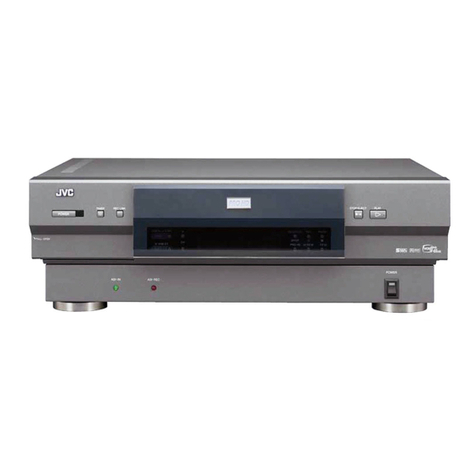
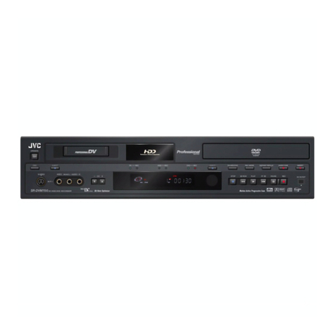
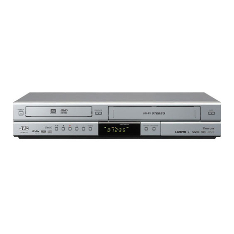
JVC DR-M150SEK User manual

SERVICE MANUAL
COPYRIGHT © 2005 Victor Company of Japan, Limited No.YD073
2005/7
DVD VIDEO RECORDER
YD07320057
DR-M150SEK
TABLE OF CONTENTS
1 PRECAUTION. . . . . . . . . . . . . . . . . . . . . . . . . . . . . . . . . . . . . . . . . . . . . . . . . . . . . . . . . . . . . . . . . . . . . . . . . 1-3
2 SPECIFIC SERVICE INSTRUCTIONS . . . . . . . . . . . . . . . . . . . . . . . . . . . . . . . . . . . . . . . . . . . . . . . . . . . . . . 1-6
3 DISASSEMBLY . . . . . . . . . . . . . . . . . . . . . . . . . . . . . . . . . . . . . . . . . . . . . . . . . . . . . . . . . . . . . . . . . . . . . . . 1-7
4 ADJUSTMENT . . . . . . . . . . . . . . . . . . . . . . . . . . . . . . . . . . . . . . . . . . . . . . . . . . . . . . . . . . . . . . . . . . . . . . . 1-11
5 TROUBLESHOOTING . . . . . . . . . . . . . . . . . . . . . . . . . . . . . . . . . . . . . . . . . . . . . . . . . . . . . . . . . . . . . . . . . 1-12
Since the whole mechanism assembly unit is replaced, the DVD recorder
mechanism of this unit need not be adjusted.
Area Suffix
EK ------------------------ U.K.
DR-M150SEK [D5R10]
Trade Mark of the DVB Digital Video Broadcasting
Project (1991 to 1996) Number : 3546
RAM/RW
STANDBY/ON
PR
PR Ð
PUSHÐOPEN

1-2 (No.YD073)
SPECIFICATION
Specifications shown are for SP mode unless otherwise specified. E. & O.E. Design and specifications subject to change without
notice.
• Manufactured under licence from Dolby Laboratories. “Dolby” and double-D symbol are trademarks of Dolby Laboratories.
• “DTS “ and “DTS DIGITAL OUT “ are trademarks of Digital Theater Systems, Inc.
• DVB (Digital Video Broadcasting) is a registered trademark of Digital Video Broadcasting Project. The Digital Video Broadcasting
system is manufactured under license from Digital Video Broadcasting Project.
• This product incorporates copyright protection technology that is protected by method claims of certain U.S. patents and other in-
tellectual property rights owned by Macrovision Corporation and other rights owners. Use of this copyright protection technology
must be authorized by Macrovision Corporation, and is intended for home and other limited viewing users only unless otherwise
authorized by Macrovision Corporation. Reverse engineering or disassembly is prohibited.
DR-M150SEK
GENERAL
Power requirement AC 220 V - 240 V~, 50 Hz/60 Hz
Power consumption Power on : 37 W
Power off : 6.4 W
Temperature Operating : 5°C to 35°C
Storage : -20°C to 60°C
Operating position Horizontal only
Dimensions (W ×H ×D) 435 mm ×70 mm ×300 mm
Weight 3.4 kg
VIDEO/AUDIO
Recordable disc DVD-RAM 12 cm (4.7 GB/9.4 GB),DVD-RAM 8 cm (1.4 GB/2.8 GB),DVD-R 12 cm(4.7 GB),
DVD-R 8 cm(1.4 GB),DVD-RW 12 cm(4.7 GB),DVD-RW 8 cm(1.4 GB)
Recording format DVD-RAM : DVD Video Recording format
DVD-R : DVD-Video format
DVD-RW : DVD-Video format, DVD Video Recording format
Recording time Maximum 8 hours (with 4.7 GB disc)
(XP) : Approx. 1 hour,(SP) : Approx. 2 hours,(LP) : Approx. 4 hours,
(EP) : Approx. 6 hours,(FR) : Approx. 1 hour - 8 hours
Audio recording system Dolby Digital (2 ch)
Linear PCM (XP mode only)
Video recording compression system MPEG2 (CBR/VBR)
Input/Output
S-video input Y:1.0 Vp-p, 75 ohms
C : 0.3 Vp-p, 75 ohms
Video input 1.0 Vp-p, 75 ohms (pin jack)
Audio input 2Vrms (pin jack)
Audio output 2Vrms (pin jack)
21-pin SCART connectors IN/OUT x 1, IN x 1
i.Link 4-pin for DV input
Component video output Y : 1.0 Vp-p, 75 ohms
PB/PR: 0.7 Vp-p, 75 ohms
Corresponding to copy protection
Digital audio output Coaxial
Corresponding to Dolby Digital and DTS Digital Surround
Bit stream
Selectable in digital audio output setting menu
TUNER/TIMER
Tuning system Frequency synthesized tuner DVB-T 2K (UK)
Channel coverage UHF : 470 MHz-850 MHz
Clock reference Quartz
Program capacity 7 days EPG programmable timer/8 programmes
Memory backup time Approx. 10 mins
ACCESSORIES
Provided accessories RF cable,21-pin SCART cable,Infrared remote control unit,”AA” battery x 2

(No.YD073)1-3
SECTION 1
PRECAUTION
1.1 Safety Precautions
(1) This design of this product contains special hardware and
many circuits and components specially for safety purpos-
es. For continued protection, no changes should be made
to the original design unless authorized in writing by the
manufacturer. Replacement parts must be identical to
those used in the original circuits. Services should be per-
formed by qualified personnel only.
(2) Alterations of the design or circuitry of the product should
not be made. Any design alterations of the product should
not be made. Any design alterations or additions will void
the manufacturers warranty and will further relieve the
manufacture of responsibility for personal injury or property
damage resulting therefrom.
(3) Many electrical and mechanical parts in the products have
special safety-related characteristics. These characteris-
tics are often not evident from visual inspection nor can the
protection afforded by them necessarily be obtained by us-
ing replacement components rated for higher voltage, watt-
age, etc. Replacement parts which have these special
safety characteristics are identified in the Parts List of Ser-
vice Manual. Electrical components having such features
are identified by shading on the schematics and by ( ) on
the Parts List in the Service Manual. The use of a substitute
replacement which does not have the same safety charac-
teristics as the recommended replacement parts shown in
the Parts List of Service Manual may create shock, fire, or
other hazards.
(4) The leads in the products are routed and dressed with ties,
clamps, tubings, barriers and the like to be separated from
live parts, high temperature parts, moving parts and/or
sharp edges for the prevention of electric shock and fire
hazard. When service is required, the original lead routing
and dress should be observed, and it should be confirmed
that they have been returned to normal, after reassem-
bling.
(5) Leakage shock hazard testing
After reassembling the product, always perform an isola-
tion check on the exposed metal parts of the product (an-
tenna terminals, knobs, metal cabinet, screw heads,
headphone jack, control shafts, etc.) to be sure the product
is safe to operate without danger of electrical shock.Do not
use a line isolation transformer during this check.
• Plug the AC line cord directly into the AC outlet. Using a
"Leakage Current Tester", measure the leakage current
from each exposed metal parts of the cabinet, particular-
ly any exposed metal part having a return path to the
chassis, to a known good earth ground. Any leakage cur-
rent must not exceed 0.5mA AC (r.m.s.).
• Alternate check method
Plug the AC line cord directly into the AC outlet. Use an
AC voltmeter having, 1,000Ωper volt or more sensitivity
in the following manner. Connect a 1,500Ω10W resistor
paralleled by a 0.15µF AC-type capacitor between an ex-
posed metal part and a known good earth ground.
Measure the AC voltage across the resistor with the AC
voltmeter.
Move the resistor connection to each exposed metal
part, particularly any exposed metal part having a return
path to the chassis, and measure the AC voltage across
the resistor. Now, reverse the plug in the AC outlet and
repeat each measurement. Voltage measured any must
not exceed 0.75 V AC (r.m.s.). This corresponds to 0.5
mA AC (r.m.s.).
1.2 Warning
(1) This equipment has been designed and manufactured to
meet international safety standards.
(2) It is the legal responsibility of the repairer to ensure that
these safety standards are maintained.
(3) Repairs must be made in accordance with the relevant
safety standards.
(4) It is essential that safety critical components are replaced
by approved parts.
(5) If mains voltage selector is provided, check setting for local
voltage.
1.3 Caution
Burrs formed during molding may be left over on some parts
of the chassis.
Therefore, pay attention to such burrs in the case of pre-
forming repair of this system.
1.4 Critical parts for safety
In regard with component parts appearing on the silk-screen
printed side (parts side) of the PWB diagrams, the parts that are
printed over with black such as the resistor ( ), diode ( )
and ICP ( ) or identified by the " " mark nearby are critical
for safety. When replacing them, be sure to use the parts of the
same type and rating as specified by the manufacturer.
(This regulation dose not Except the J and C version)
Good earth ground
Place this
probe on
each exposed
metal part.
AC VOLTMETER
(Having 1000
ohms/volts,
or more sensitivity)
1500 10W
0.15 F AC TYPE
1-4 (No.YD073)
1.5 Preventing static electricity
Electrostatic discharge (ESD), which occurs when static electricity stored in the body, fabric, etc. is discharged, can destroy the laser
diode in the traverse unit (optical pickup). Take care to prevent this when performing repairs.
1.5.1 Grounding to prevent damage by static electricity
Static electricity in the work area can destroy the optical pickup (laser diode) in devices such as DVD players or recorder.
Be careful to use proper grounding in the area where repairs are being performed.
(1) Ground the workbench
Ground the workbench by laying conductive material (such as a conductive sheet) or an iron plate over it before placing the
traverse unit (optical pickup) on it.
(2) Ground yourself
Use an anti-static wrist strap to release any static electricity built up in your body.
(3) Handling the optical pickup
• In order to maintain quality during transport and before installation, both sides of the laser diode on the replacement optical
pickup are shorted. After replacement, return the shorted parts to their original condition.
(Refer to the text.)
• Do not use a tester to check the condition of the laser diode in the optical pickup. The tester's internal power source can easily
destroy the laser diode.
1.6 Handling the traverse unit (optical pickup)
(1) Do not subject the traverse unit (optical pickup) to strong shocks, as it is a sensitive, complex unit.
(2) Cut off the shorted part of the flexible cable using nippers, etc. after replacing the optical pickup. For specific details, refer to the
replacement procedure in the text. Remove the anti-static pin when replacing the traverse unit. Be careful not to take too long
a time when attaching it to the connector.
(3) Handle the flexible cable carefully as it may break when subjected to strong force.
(4) I t is not possible to adjust the semi-fixed resistor that adjusts the laser power. Do not turn it.
1M
Conductive material
(conductive sheet) or iron palate
(caption)
Anti-static wrist strap

(No.YD073)1-5
1.7 Important for laser products
1.CLASS 1 LASER PRODUCT
2.DANGER : Invisible laser radiation when open and inter
lock failed or defeated. Avoid direct exposure to beam.
3.CAUTION : There are no serviceable parts inside the
Laser Unit. Do not disassemble the Laser Unit. Replace
the complete Laser Unit if it malfunctions.
4.CAUTION : The CD,MD and DVD player uses invisible
laser radiation and is equipped with safety switches which
prevent emission of radiation when the drawer is open and
the safety interlocks have failed or are defeated. It is
dangerous to defeat the safety switches.
5.CAUTION : If safety switches malfunction, the laser is able
to function.
6.CAUTION : Use of controls, adjustments or performance of
procedures other than those specified here in may result in
hazardous radiation exposure.
!
Please use enough caution not to
see the beam directly or touch it
in case of an adjustment or operation
check.
REPRODUCTION AND POSITION OF LABEL
On mechaism assembly

1-6 (No.YD073)
SECTION 2
SPECIFIC SERVICE INSTRUCTIONS
This service manual does not describe SPECIFIC SERVICE INSTRUCTIONS.

(No.YD073)1-7
SECTION 3
DISASSEMBLY
3.1 Main body section
3.1.1 Remove the top cover (See figure 1)
(1) Remove the four screws Aattaching the top cover on both
sides of the main body.
(2) Remove the five screws Battaching the top cover on the
back of the main body.
(3) Raise the both sides and lower part of the rear of the top
cover, with opening them slightly in an outward direction.
And the top cover will be removed.
Fig.1
3.1.2 Remove the front panel assembly (See figure2, figure 3)
• Prior to performing the following procedure, remove the top
cover.
• There is no need to remove the mechanism assembly.
(1) Disconnect the card wires from connectors CN7002,
CN7003, CN4001 on the main board and display board.
(2) Remove the two screws Cattaching the front panel assem-
bly on the bottom of the main body.
(3) Hooks aand bare removed respectively, and the front
panel assembly is removed.
Fig.2
Fig.3
B
B
Ax 2
TOP COVER
TOP COVER
TOP COVER
B
Ax 2
B
B
CN7002
CN4001 CN7003
Main board
Display board
Front panel assembly
Hook a
Hook a
Hook b
Hook b
Front panel assembly
C
C

1-8 (No.YD073)
3.1.3 Remove the drive unit (See figure 4)
• Prior to performing the following procedure, remove the top
cover.
• There is no need to remove the front panel assembly.
(1) Disconnect the socket wire from connector CN5301 on the
main board.
(2) Disconnect the card wire from connector CN2201 on the
digital board.
(3) Remove the four screws Dattaching the drive unit.
Fig.4
3.1.4 Remove the digital board (See figure 5)
• Prior to performing the following procedure, remove the top
cover.
(1) Disconnect the card wire from connectors CN2201,
CN1404, CN1103 on the digital board.
(2) Disconnect the socket wire from connectors CN1101,
CN1102, CN1801 on the digital board.
(3) Remove the four screws Eattaching the digital board.
Fig.5
D
Drive unit
D
CN2201 D
DCN5301
Digital board
Main board
CN2201
CN1404
Digital board
E
E
E
E
CN1103
CN1801 CN1101
CN1102

(No.YD073)1-9
3.1.5 Remove the main board (See figure 6, figure 7)
• Prior to performing the following procedure, remove the top
cover, drive unit.
(1) Disconnect the card wire from connectors CN4001,
CN4103, CN6801, CN6802 on the main board.
(2) Disconnect the socket wire from connectors CN1101,
CN1102, CN7001 on the digital board and display board.
(3) Disconnect the socket wire from connector CN5303, on the
main board.
(4) Disconnect the power cord from connector CN5001, on the
main board.
(5) Remove the six screws Fattaching the main board.
(6) Remove the seven screws Gattaching the rear panel with
main board.
Fig.6
Fig.7
3.1.6 Remove the dispiay board (See figure 8)
• Prior to performing the following procedure, remove the top
cover, drive unit, front panel assembly.
(1) Disconnect the socket wire from connector CN7001 on the
display board.
(2) Remove the two screws Hattaching the display board.
Fig.8
F
CN5303
Digital board F
FF
CN5001
F
F
Display board
Main board
CN4103
CN6801
CN6802
CN4001
CN1102
CN1101
CN7001
Rear panel
G
Display board HH CN7001

1-10 (No.YD073)
3.1.7 Remove the digital tuner unit (See figure 9,figure 10)
• Prior to performing the following procedure, remove the top
cover.
(1) Disconnect the card wire from connectors CN6801,
CN6802, CN1404 on the main board and digital board.
(2) Remove the two screws Iattaching the digital tuner unit.
(3) Remove the one screw Jattaching the rear panel with dig-
ital tuner unit.
Fig.9
Fig.10
I
CN6801
CN1404
CN6802
Digital tuner unit
Digital board
Main board
Rear panel
J

(No.YD073)1-11
SECTION 4
ADJUSTMENT
This service manual does not describe ADJUSTMENT.

1-12 (No.YD073)
SECTION 5
TROUBLESHOOTING
5.1 JIG Mode
The following remote control units are required to set and cancel JIG mode.
For setting : a remote control unit attached to product.
For cancellation : JIG remote control unit (part number : PTU94023B)
When the main body is set to JIG mode and when the main body is under JIG mode, the remote control unit attached to product op-
erates only in "Remote Control Code 1". Since main body is in "Remote Control Code 3" when it is shipped and just after its batteries
are changed, "Remote Control Code 3" needs to be changed to "Remote Control Code 1."
< Changing Remote Control Code >
(1) Press the numeric button "1" of the remote control unit while pressing the "SET UP" button of the remote control unit. Then,
press the "ENTER" button, and then release the "SET UP" button.
(2) Press the "PLAY" button of the main body for five seconds or longer while the main body is in stand-by mode, and a current
remote control code of the main body is displayed in FL indicator of the main body.
(3) While keeping the state of (2), press the "STOP" button of the remote control unit toward the main body.
(4) The code that was set by the remote control unit blinks for 5 seconds, before the code is set to the main body.
When the FL indicator changes to "DVD1," it shows that the remote control code has been changed to "1."
Custom code
43:A Code
53:B Code
6F:C Code
7F:D Code
Data code
Initial mode
Remote control unit
attached to product JIG remote control unit
3
JIG remote control unit
[Data transmission]
Set the data code,
and then press the
" " button.
RAM/RW
STANDBY/ON
PR
PR Ð
PUSHÐOPEN
(1)b
(1)c
(1)a
(3)
(2)
(2),(4)
"(1) a-c" shows the order of pressing the buttons.
DVD 1

(No.YD073)1-13
5.1.1 Setting JIG mode
To display SYSTEM INFO or to upgrade firmware, the main body needs to be set to JIG mode.
(1) Turn the main body ON.
(2) Press the buttons of the remote control unit attached to product in the following order : "SET UP" →"2" →"8" →"ENTER"
(3) When a colon ":" between "hour" and "minute" of a clock in FL indicator blink, it means that the main body has been set to JIG
mode properly.
(4) Turn the main body OFF, and then turn it ON again.
*Once the main body is set to JIG mode, the JIG mode cannot be cancelled even if the power cord is pulled out from the wall
socket.
5.1.2 Canceling JIG mode
(1) Transmit "43-9D" to the main body by using JIG remote control unit.
(Please end a setting menu pushing “SET UP” button of the remote control unit appended to the commodity beforehand when
a setting menu is displayed.)
(2) A colon ":" between "hour" and "minute" of a clock in FL indicator light.
(3) Turn the main body OFF, and then turn it ON again.
NOTE:
After repair work, be sure to cancel JIG mode. Before returning product to a user, confirm that a colon ":" between "hour" and
"minute" of a clock in FL indicator light.
Not in JIG mode In JIG mode
[ Example ]
15 : 07 15 07
A colon blinks.
RAM/RW
STANDBY/ON
PR
PR Ð
PUSHÐOPEN
(2)b
(2)c
(2)d
(2)a
(3)(1),(4)
"(2) a-d" shows the order of pressing the buttons.
15:07

1-14 (No.YD073)
5.2 Displaying SYSTEM INFO
In the SYSTEM INFO there is information including firmware versions of the main body and the drive unit.
(1) Set the main body to JIG mode.
(2) Transmit "43-8B" to the main body by using JIG remote control unit.
(Please end a setting menu pushing “SET UP” button of the remote control unit appended to the commodity beforehand when
a setting menu is displayed.)
(3) SYSTEM INFO menu is displayed in the television screen.
(4) To move cursor in SYSTEM INFO, use the "", "", "", and "" buttons of a remote control unit attached to product.
NOTE :
Items other than the ones described above are not used in service work.
(5) To quit the SYSTEM INFO menu, transmit "43-8B" to the main body by using JIG remote control unit.
(6) Cancel JIG mode.
SYSTEM INFO
VERSION INITIALIZE INFORMATION
Silicon version of E5
BSP
Drive firmware version
Drive last error
1B0
1.2/101
P013
00 00 00
DVB-T version 02. 0A
Version of firmware of mechanism drive
Version of firmware of digital video broadcasting tune
r
ENTER
SELECT
SELECT WITH [CURSORS]
THEN PRESS [ENTER]
SET UP
ENTER
SELECT
SELECT WITH [CURSORS]
THEN PRESS [ENTER]
SET UP
< VERSION >
SYSTEM INFO
VERSION INITIALIZE INFORMATION
CPRM Key Download
C-Ware / A-Ware
JVRI / Host
1394 / OSD
Analog / BE-R / FE-R
Done
PROD127 / JVC03_49
0136 / V0276E
0055 / 2005M04
100 / 2 / 2
Version of firmware
This part is updated after the firmware of the
main body is updated.
System controller version
/ Region code (Backend) / Region code (Frontend)
< INFORMATION >

(No.YD073)1-15
5.3 Updating the firmware of the main body or digital video broadcasting tuner
• Firmware update disk supports CD-R media.
• When firmware update is necessary. information is available from the homepage of DIGITAL VIDEO STORAGE CATEGORY, CS
group.
• Please check the details of the update disc creation method by JS-NET.
(1) Set the main body to JIG mode.
(2) Transmit "43-70" to the main body by using JIG remote control unit.
(3) "UPDATE" appears in FL indicator. Load disk for update on the tray, and close the tray.
(4) Update processing is started automatically.
(5) Then, "FW UPDATE" appears in FL indicator. It takes approx. 3 minutes at maximum to update firmware.
(6) The tray is ejected. Then, take out the disk and close the tray.
(7) Turn the main body OFF, and pull out the power cord from the wall socket. Then, plug the power cord into the wall socket.
(8) "PLEASE" and "WAIT" blink alternately and it is displayed in FL indicator. Then, turn the main body ON.
(9) Display the SYSTEM INFO menu, and check the version of the firmware.
(10) Cancel JIG mode.
ATTENTION :
Firmware may sometimes not be update successfully.
If firmware is not update successfully, the tray opens, and "ERROR" appears in FL indicator.
If firmware is update successfully, the tray opens, and "OPEN" appears in FL indicator.
If the power cord is pulled out from the wall socket while "ERROR" appears, data in the flash memory is destroyed and the main
body cannot start: the flash memory needs to be replaced.
After update procedure, pay enough attention to FL indicator when the tray opens.
When "ERROR" appears, update firmware again in the following way to restore the firmware.
(1) Transmit "43-70" to the main body by using JIG remote control unit while the tray opens.
(2) When "UPDATE" appears in FL indicator, close the tray and make the main body read the disk. Update starts.
(3) The following procedures are the same as a usual update.
5.4 Updating the firmware of the drive unit
• Firmware update disc supports only DVD-RAM media.
• When firmware update is necessary, written discs are distributed by DIGITAL VIDEO STORAGE CATEGORY, CS group.
(1) Turn the main body ON.
(2) Load the update DVD-RAM disc on the tray and close the tray.
(3) “READING” is displayed in the FL indicator and the update is started.
(4) In a short while “READING” in the FL indicator disappears, open the tray to remove the disc and close the tray.
(5) Turn the power OFF and pull out the power code from the wall socket, then plug the power cord into the wall socket again.
(6) Set to the JIG mode and check the firmware version of the drive.
5.5 Setting after the drive unit replacement
When the drive unit is replaced, it is necessary to set a region code. Service drive units for replacement are not set for any region
code, and they are in an indefinite condition.
Make sure to set region code after attaching the drive unit to the main body.
Without the setting of the region code, discs that have regions cannot be played back.
(1) Replace a drive unit.
(2) Turn POWER switch of the unit ON.
(3) Set the main body to JIG mode.
(4) Insert a DVD-RAM disc in the unit to make the unit read the DVD-RAM disc.(The DVD-RAM disk used in this procedure is not a
disk for upgrade. If it is a DVD-RAM disk, it is good anything.)
(5) Send "43-F2" to the unit by using JIG remote control unit.
(6) "2 REGION" is displayed on FL display.
(7) Set the unit to STANDBY.
(8) Turn the POWER switch ON.
(9) To cancel JIG MODE, send "43-9D" to the unit by using JIG remote control unit.
(10) Colon is displayed on a clock on FL display.
(11) Setting is completed in the procedure above.

1-16 (No.YD073)
5.6 Taking out a disc
5.6.1 Method 1
There is compulsive tray ejection mode by electric operation.
(1) AC Plug is pulled out at once and inserted again.
(2) It is displayed on FL display as "PLEASE" and "WAIT" blink alternately, and while it blinks, pushing the EJECT button of a main
body is continued.
(3) After a while, a tray opens (About 20 seconds).
(4) A disk is removed, the tray is pushed, and a tray is made to close.
(5) "PLEASE" and "WAIT" blink alternately and it is displayed in FL indicator, and it will be in a standby state.
(6) If the POWER button is pushed, it will usually be operating.
5.6.2 Method 2
When the disc cannot be removed by operating above “Method 1” , open the front door of the main body manually and directly press
the EJECT button located in the lower right of the drive unit.
5.6.3 Method 3
When neither “Method 1” nor “Method 2” can remove the disc, the tray can be ejected mechanically without turning the power on.
(1) Open the front door of the main body manually.
(2) Insert a fine wire (e.g. a straightened paper clip) into the hole in the lower part of the tray of the drive unit.
(3) As the tray ejects a little, pull out the tray manually.
5.7 Exchanging the fitting
As the fitting that comes with the service drive unit cannot be used, make sure to attach a service fitting when the drive unit is ex-
changed. The fitting that is removed from the old drive unit can be attached to the new drive unit.
The fitting can be removed by pulling upwards while opening out the lower part of the fitting outwards.
Front door Tray Hole EJECT Button
Fitting
Tray

(No.YD073)1-17
5.8 Initialization to the factory shipment state
When the initialization is operated, internal information changes as follows. It is essential to obtain the client’s permission before the
operation.
• All DVD library is all deleted.
• All the DVD initial settings go back to the initial status.
(1) Set to the JIG mode.
(2) Transmit “43-6F” with the JIG remote control unit.
(3) FL indicator displays “FACTORY”, and changes to “CHECK OK” after blinking for a short while.
(4) Pull out the power code from the wall socket.
(5) The JIG mode is forced to cancel at the same time with the initialization, check whether the JIG mode is canceled by plugging
the power code into the wall socket again. (The colon “:” in time display should be continuously ON, not blinking.)
If the JIG mode is not canceled, transmit “43-9D” with JIG remote control unit to cancel the JIG mode.
5.9 When it is displayed in FDP, 'RESETTING'
When the following operations are carried out, “RESETTING” is displayed in the FDP of the main body.
(1) When the “POWER” button and the “STOP” button of the main body are pressed at the same time
(2) When the code “9B” is transmitted to the main body by using JIG remote control unit
(3) When transmission failure occurs between the main CPU and the DVD host CPU due to defect
If “RESETTING” is displayed in the FDP after the power code is plugged into the outlet, check the followings.
• The peripheral circuitry of each microcomputer
• Whether the wire between the DVD drive and the board is properly connected
• Whether the wire between the main board and the digital board is properly connected

(No.YD073)
VPT
Printed in Japan
AV & MULTIMEDIA COMPANY DIGITAL VIDEO STORAGE CATEGORY 12, 3-chome, Moriya-cho, kanagawa-ku, Yokohama, kanagawa-prefecture, 221-8528, Japan
Victor Company of Japan, Limited

SCHEMATIC DIAGRAMS
DVD VIDEO RECORDER
No.YD073SCH
2005/7
COPYRIGHT 2005 Victor Company of Japan, Limited
DR-M150SEK
CD-ROM No.SML200507
Since the whole mechanism assembly unit is replaced, the DVD recorder
mechanism of this unit need not be adjusted.
Area Suffix
EK ------------------------ U.K.
DR-M150SEK [D5R10]
Trade Mark of the DVB Digital Video Broadcasting
Project (1991 to 1996) Number : 3546
RAM/RW
STANDBY/ON
PR
PR Ð
PUSHÐOPEN

!
CHARTS AND DIAGRAMS
NOTES OF SCHEMATIC DIAGRAM
Safety precautions
The Components indentified by the symbol are
critical for safety. For continued safety, replace safety
critical components only with manufacturer's recom-
mended parts.
1. Units of components on the schematic diagram
Unless otherwise specified.
1) All resistance values are in ohm. 1/6 W, 1/8 W (refer to
parts list).
Chip resistors are 1/16 W.
K: KΩ(1000Ω), M: MΩ(1000KΩ)
2) All capacitance values are in µF, (P: PF).
3) All inductance values are in µH, (m: mH).
4) All diodes are 1SS133, MA165 or 1N4148M (refer to parts
list).
2. Indications of control voltage
AUX : Active at high.
AUX or AUX(L) : Active at low.
3. Interpreting Connector indications
Note: If the voltages are not indicated on the schematic
diagram, refer to the voltage charts.
12 3
2.5
(5.0) 1.8
PB and REC modes
(Voltage of PB and REC modes
are the same)
PB mode
REC mode
4. Voltage measurement
1) Regulator (DC/DC CONV) circuits
REC : Colour bar signal.
PB : Alignment tape (Colour bar).
— : Unmeasurable or unnecessary to measure.
2) Indication on schematic diagram
Voltage indications for REC and PB mode on the sche-
matic diagram are as shown below.
6. Indication of the parts for adjustments
The parts for the adjustments are surrounded with the circle
as shown below.
7. Indication of the parts not mounted on the circuit board
“OPEN” is indicated by the parts not mounted on the circuit
board.
R216
OPEN
1
2
3
1
2
3
1
2
3
1
4
2
3
Removable connector
Wire soldered directly on board
Non-removable Board connector
Board to Board
Connected pattern on board
The arrows indicate signal path
Note: The Parts Number, value and rated voltage etc. in
the Schematic Diagram are for references only.
When replacing the parts, refer to the Parts List.
CIRCUIT BOARD NOTES
1. Foil and Component sides
1) Foil side (B side) :
Parts on the foil side seen from foil face (pattern face)
are indicated.
2) Component side (A side) :
Parts on the component side seen from component face
(parts face) indicated.
2. Parts location guides
Parts location are indicated by guide scale on the circuit board.
LOCATION
REF No.
IC101 B C 6 A
IC Category : IC
Horizontal “A” zone
Vertical “6” zone
B : Foil side
(A : Component side)
C : Chip component
D : Discrete component)
2-1 2-2
Other manuals for DR-M150SEK
1
Table of contents
Other JVC DVR manuals

JVC
JVC DR-MX10SEK User manual

JVC
JVC VR-716E User manual

JVC
JVC DR MV79B - DVDr/ VCR Combo User manual

JVC
JVC DR-M10STW User manual

JVC
JVC DR-MV99BU User manual

JVC
JVC LST0601-001B User guide

JVC
JVC 0503-AH-ID-JVE User manual

JVC
JVC DR-M10S User manual

JVC
JVC DR-M70SEK User manual

JVC
JVC DRMV80B - DVDr/ VCR Combo User manual

JVC
JVC HR-A630MS User manual

JVC
JVC DR-MH300SE/BE User manual

JVC
JVC DR-M10S User manual

JVC
JVC DR-M10SEF User manual

JVC
JVC SR-MV45 User manual

JVC
JVC LPT0923-001B User manual

JVC
JVC DR-M150SEK User manual

JVC
JVC SR- DVM600U User manual

JVC
JVC DRMV78B - DVDr/ VCR Combo User manual

JVC
JVC DR MV79B - DVDr/ VCR Combo User manual