JVC TH-A25 User manual

LVT1111-001B
[J]
INSTRUCTIONS
DVD DIGITAL THEATER SYSTEM
TH-A25
Consists of XV-THA25 and SP-THA25
SOUND
VOLUME
SOURCE
STANDBY
STANDBY/ON
DVD DIGITAL THEATER SYSTEM TH-A25
For Customer Use:
Enter below the Model No. and Serial No.
which are located either on the rear, bot-
tom or side of the cabinet. Retain this
information for future reference.
Model No.
Serial No.
Cover_TH_A25[J].p65 03.10.15, 11:08 AM3

G-1
Warnings, Cautions and Others
CAUTION: TO REDUCE THE RISK OF ELECTRIC SHOCK.
DO NOT REMOVE COVER (OR BACK)
NO USER SERVICEABLE PARTS INSIDE.
REFER SERVICING TO QUALIFIED SERVICE PERSONNEL.
RISK OF ELECTRIC SHOCK
DO NOT OPEN
The lightning flash with arrowhead symbol,
within an equilateral triangle is intended to
alert the user to the presence of uninsulated
"dangerous voltage" within the product’s
enclosure that may be of sufficient
magnitude to constitute a risk of electric
shock to persons.
The exclamation point within an equilateral
triangle is intended to alert the user to the
presence of important operating and
maintenance (servicing) instructions in the
literature accompanying the appliance.
CAUTION
CAUTION
To reduce the risk of electrical shocks, fire, etc.:
1. Do not remove screws, covers or cabinet.
2. Do not expose this appliance to rain or moisture.
WARNING: TO REDUCE THE RISK OF FIRE
OR ELECTRIC SHOCK, DO NOT EXPOSE
THIS APPLIANCE TO RAIN OR MOISTURE.
Caution –– STANDBY/ON switch!
Disconnect the mains plug to shut the power off completely. The
STANDBY/ON switch in any position does not disconnect.
For U.S.A
This equipment has been tested and found to comply with the limits
for a Class B digital device, pursuant to part 15 of the FCC Rules.
These limits are designed to provide reasonable protection against
harmful interference in a residential installation.
This equipment generates, uses and can radiate radio frequency
energy and, if not installed and used in accordance with the
instructions, may cause harmful interference to radio
communications. However, there is no guarantee that interference
will not occur in a particular installation. If this equipment does cause
harmful interference to radio or television reception, which can be
determined by turning the equipment off and on, the user is
encouraged to try to correct the interference by one or more of the
following measures:
Reorient or relocate the receiving antenna.
Increase the separation between the equipment and receiver.
Connect the equipment into an outlet on a circuit different from that
to which the receiver is connected.
Consult the dealer or an experienced radio/TV technician for help.
Note to CATV system installer:
This reminder is provided to call the CATV system installer’s
attention to Section 820-40 of the NEC which provides guidelines
for proper grounding and, in particular, specifies that the cable
ground shall be connected to the grounding system of the
building, as close to the point of cable entry as practical.
IMPORTANT FOR LASER PRODUCTS
1. CLASS 1 LASER PRODUCT
2. CAUTION: Do not open the top cover. There are no user
serviceable parts inside the Unit; leave all servicing to qualified
service personnel.
3. CAUTION: Visible and invisible laser radiation when open and
interlock failed or defeated. Avoid direct exposure to beam.
4. REPRODUCTION OF LABEL: CAUTION LABEL, PLACED
INSIDE THE UNIT.
Caution: Proper Ventilation
To avoid risk of electric shock and fire and to protect from damage.
Locate the apparatus as follows:
Front: No obstructions open spacing.
Sides: No obstructions in 10 cm from the sides.
Top: No obstructions in 10 cm from the top.
Back: No obstructions in 15 cm from the back
Bottom: No obstructions, place on the level surface.
In addition, maintain the best possible air circulation as illustrated.
XV-THA25
Front
Spacing 15 cm or more
Floor
Stand height
15 cm or more
Wall or obstructions
Safety_TH_A25[J].p65 03.8.31, 2:08 PM1

1
Table of Contents
Parts Identification ...................................... 2
Center Unit ................................................................................. 2
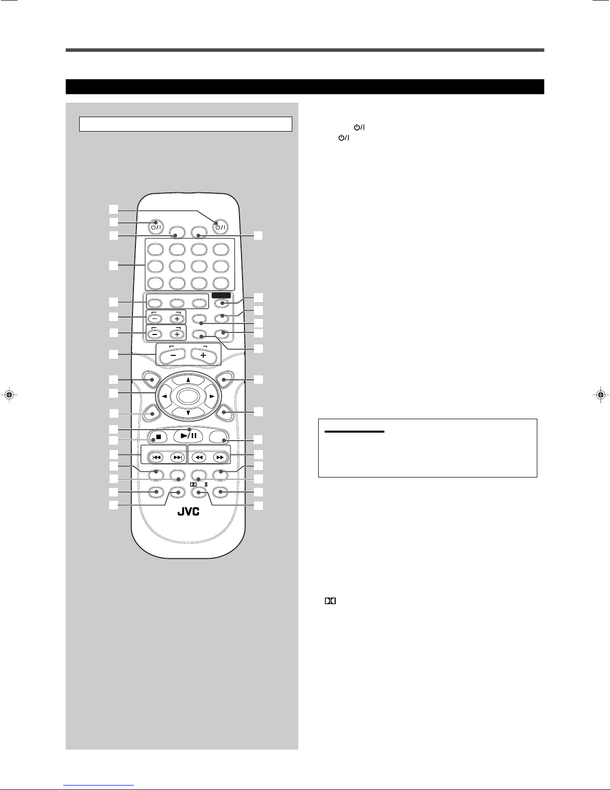
Remote Control .......................................................................... 3
Getting Started ........................................... 4
Before Installation ...................................................................... 4
Checking the Supplied Accessories ........................................... 4
Putting Batteries in the Remote Control .................................... 4
Connecting the FM and AM Antennas ....................................... 5
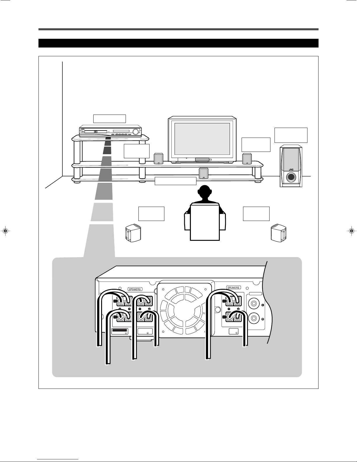
Speaker Layout Diagram ............................................................ 6
Connecting the Speakers ............................................................ 7
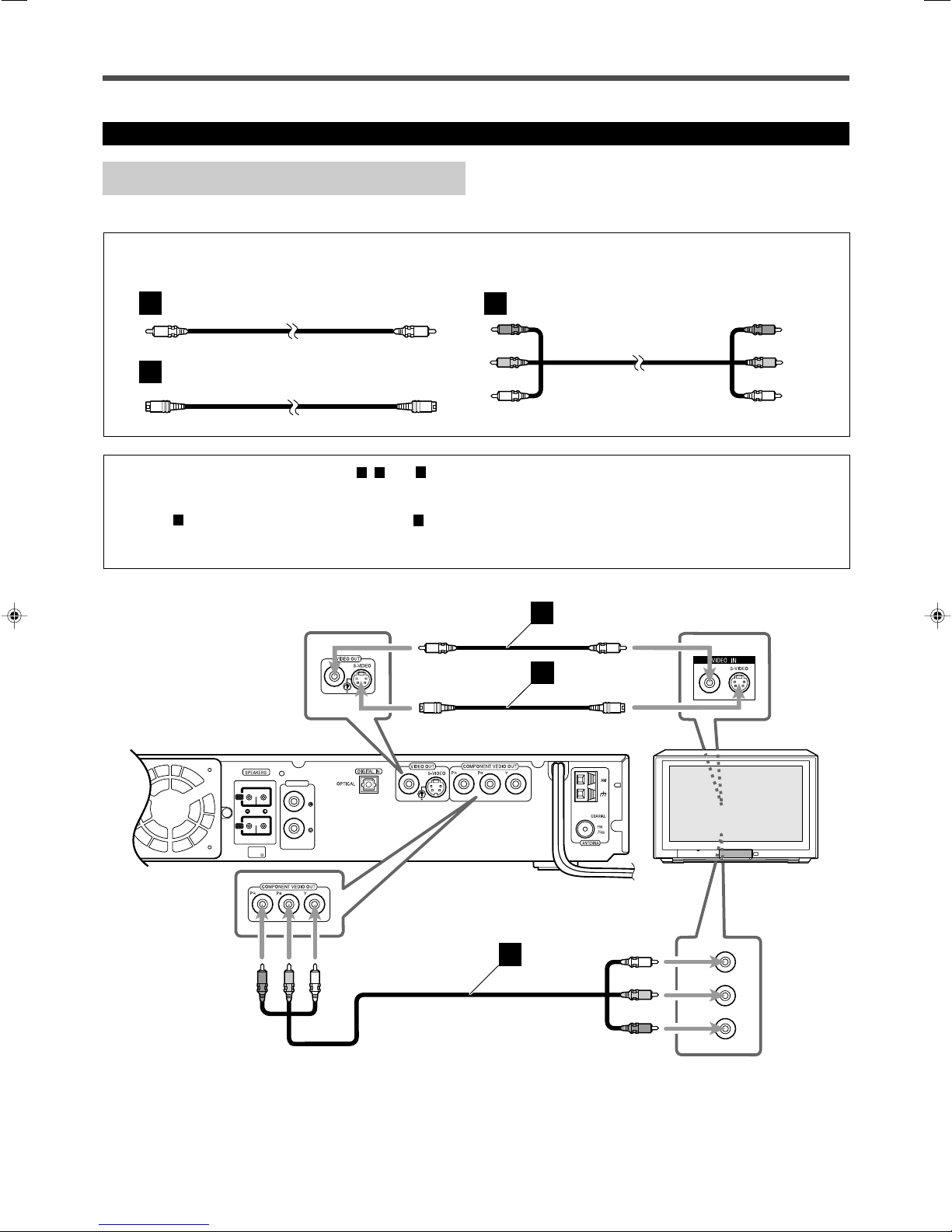
Connecting Audio/Video Component ........................................ 8
TV Settings ............................................... 10
Changing the Scanning Mode .................................................. 10
Operating TV ............................................. 11
Basic Disc Operations ................................ 12
1 Turn On the Power ............................................................... 12
2 Select the Source .................................................................. 12
3 Load a Disc .......................................................................... 12
4 Start Playback ...................................................................... 13
5 Adjust the Volume ................................................................ 13
6 Activate Surround ................................................................ 13
Moving to Another Chapter/Track/File .................................... 14
Stopping Playback .................................................................... 14
Basic Tuner Operations .............................. 15
1 Turn On the Power ............................................................... 15
2 Select the Band .................................................................... 15
3 Adjust the Volume ................................................................ 15
4 Tune into a Station ............................................................... 15
Other Basic Operations .............................. 16
Enjoying Sounds from the External Component ..................... 16
Turning Off the Power with the Timer ..................................... 16
Adjusting the Display Brightness ............................................. 16
Creating Realistic Sound Fields ................... 17
Using the Test Tone .................................................................. 17
Adjusting the Sound ................................................................. 17
7Basic sound adjustment procedure ....................................... 18
Surround Mode Introduction .................................................... 19
7Dolby Digital and DTS Digital Surround............................. 19
7Dolby Pro Logic II modes .................................................... 19
Activating the Surround Mode ................................................. 20
Disc Introduction—DVD/VCD/SVCD/CD ...... 21
Disc Playback ............................................ 22
Using the On-Screen Bar ......................................................... 22
7Showing the On-Screen Bar ................................................. 22
7Basic operation through the On-Screen Bar ......................... 23
Selecting the Audio Languages ................................................ 24
Selecting the Subtitles .............................................................. 24
Selecting the Playback Channel ............................................... 25
Selecting the Multi-Angle Views ............................................. 25
Checking the Remaining Time ................................................. 25
Disc Menu-Driven Playback .................................................... 26
Moving to a Particular Portion Directly ................................... 27
Searching for a Particular Point ............................................... 27
Repeating Playback .................................................................. 28
7Repeat Play ........................................................................... 28
7A–B Repeat .......................................................................... 28
Special Picture Playback .......................................................... 29
7Still Picture/Frame-by-Frame Playback ............................... 29
7Slow Motion Playback ......................................................... 29
7Zoom .................................................................................... 29
MP3/JPEG Introduction ............................ 30
MP3/JPEG Playback ................................. 31
Starting Playback ..................................................................... 31
Showing the On-Screen Bar ..................................................... 31
Operations Using the On-Screen Display ................................ 32
Selecting a Particular File/Folder Directly ............................... 33
Repeating Playback .................................................................. 33
Browsing Pictures in the Current Folder .................................. 33
Rotating and Flipping a Picture................................................ 33
Tuner Operations ....................................... 34
Tuning in Stations .................................................................... 34
Using Preset Tuning ................................................................. 35
Selecting the FM Reception Mode ........................................... 35
Setting Up the DVD Preferences ................. 36
Setting the System Preferences ................................................ 36
7The basic procedure to set up the system preferences .......... 37
7To adjust the DRC (Dynamic Range Compression) ............. 37
Setting the Preferences ............................................................. 38
7The basic procedure to set up preferences ............................ 38
7To set the parental (rating) level ........................................... 39
7To change the password ........................................................ 39
7To release the parental lock temporarily .............................. 40
7Language Code List ............................................................. 40
Maintenance ............................................. 41
Troubleshooting ......................................... 42
Specifications............................................ 43
01_11_TH_A25[J].p65 03.10.15, 11:13 AM1

2
Parts Identification
Front Panel
See pages in the parentheses for details.
Display
1P.SCAN indicator (10)
2Digital signal indicators (13, 19, 20)
• LINEAR PCM, DOLBY DIGITAL, and DTS.
3TITLE indicator (13)
• Indicates the current title number with main display.
4PBC (Play Back Control) indicator
• Goes on when the PBC function is activated.
5CHAP (chapter) indicator (13)
• Indicates the current chapter number with main display.
6PRGM (program) indicator (35)
7Tuner mode indicators (15, 34, 35)
• ST (stereo) and TUNED
8Audio channel indicators
• Indicates audio channels currently being reproduced.
9Dolby PRO LOGIC II indicator (13, 19, 20)
pMain display
qFrequency unit indicators
• kHz (for AM band station) and MHz (for FM band
station)
Display
Center Unit
See pages in the parentheses for details.
Front Panel
1STANDBY/ON button and STANDBY lamp (12–15)
2Disc tray (12)
3Remote sensor
4Display
5VOLUME control (13, 15)
60(open/close) button (12, 14)
• Pressing this button also turns on the power and
changes the source to the DVD/CD.
73/8(play/pause) button (13, 14, 31)
• Pressing this button also turns on the power and
changes the source to the DVD/CD.
8Multi operation buttons
•4, ¢, and 7
9SOURCE button (12, 15, 16)
VOLUME
SOURCE
STANDBY
STANDBY/ON
DVD DIGITAL THEATER SYSTEM TH-A25
2
6 7 98
4 5
3
1
MHz
k
Hz
PRGM
CHAP TUNEDPBC
TITLEP.SCAN
LINEAR PCM
ST
L C R
SW
LS SRS
q9
5 63 42 7
p8
1
01_11_TH_A25[J].p65 03.8.31, 2:08 PM2

3
Remote Control
See pages in the parentheses for details.
1AUDIO button (12, 14, 15)
2TV button (11,12)
3DIMMER button (16)
4• Number buttons
• MEMORY button (35)
• CANCEL button
5Source selecting buttons
• DVD, FM/AM, AUX (10, 12, 15, 16)
• Pressing one of these buttons also turns on the power.
6TV CH + and – buttons (11)
7TV VOL + and – buttons (11)
8AUDIO VOL + and – buttons (13, 15)
9TOP MENU button (26)
p•3, 2, 5, and ∞buttons
• ENTER button
qCHOICE/TIME button (25, 31, 37–39)
w3/8button
e7button
r4and ¢buttons
tAUDIO button (24, 25)
ySUBTITLE button (24)
u• SLOW button (29)
• PROGRESSIVE button (10)
iRETURN button (26)
oSLEEP button (16)
;SOUND button (18)
aTEST TONE button (17)
sCONTROL TV button (11)
IMPORTANT:
When you press CONTROL TV, some buttons on the remote control
cannot work for operating the center unit. To operate the center
unit, press DVD, FM/AM, or AUX depending on your target
operation.
dMUTING button (13)
fTV/VIDEO button (11, 12)
gMENU button (26, 33)
hON SCREEN button (22–28, 31)
jSTEP button (29)
k• 1and ¡buttons
• TUNING UP and DOWN buttons (15, 34)
lZOOM button (29)
/ANGLE button (25)
z• REPEAT button (28, 33)
• FM MODE button (35)
PL II button (13, 20)
Remote Control
1
2
3
4
5
6
7
8
9
y
p
q
e
w
u
i
;
a
s
d
r
t
f
g
h
k
l
/
o
z
AUDIOTV
SLEEPDIMMER
DVD FM/AM
TV CH
AUX
TV/VIDEO
MUTING
CONTROL
TEST TONE
TOP
MENU MENU
CHOICE/TIME
DOWN - TUNING - UP
AUDIO
SLOW RETURN PL
PROGRESSIVE
RM-STHA25J
DVD THEATER SYSTEM
REPEAT
SUBTITLE ANGLE ZOOM
ON SCREEN
TV VOL
AUDIO VOL
1234
5678
9
TV
0
MEMORY
CANCEL
ENTER
SOUND
STEP
FM MODE
j
01_11_TH_A25[J].p65 03.8.31, 2:08 PM3

4
Getting Started
Putting Batteries in the Remote Control
Before using the remote control, put two supplied batteries first.
• When using the remote control, aim the remote control directly at
the remote sensor on the center unit.
1. On the back of the remote control, remove the
battery cover.
2. Insert batteries. Make sure to match the polarity:
(+) to (+) and (–) to (–).
3. Replace the cover.
If the range or effectiveness of the remote control decreases, replace
the batteries. Use two R6P(SUM-3)/AA(15F) type dry-cell batteries.
CAUTION:
Follow these precautions to avoid leaking or cracking cells:
•Place batteries in the remote control so they match the polarity: (+)
to (+) and (–) to (–).
•Use the correct type of batteries. Batteries that look similar may
differ in voltage.
•Always replace both batteries at the same time.
•Do not expose batteries to heat or flame.
Before Installation
General Precautions
• DO NOT insert any metal object into the center unit.
• DO NOT disassemble the center unit or remove screws, covers, or
cabinet.
• DO NOT expose the center unit to rain or moisture.
Locations
• Install the center unit in a location that is level and protected from
moisture.
• The temperature around the center unit must be between 5˚C and
35˚C.
• Make sure there is good ventilation around the center unit. Poor
ventilation could cause overheating and damage the center unit.
Handling the center unit
• DO NOT touch the power cord with wet hands.
• DO NOT pull on the power cord to unplug the cord. When
unplugging the cord, always grasp the plug so as not to damage
the cord.
• Keep the power cord away from the connecting cords and the
antenna. The power cord may cause noise or screen interference. It
is recommended to use a coaxial cable for antenna connection,
since it is well-shielded against interference.
• When a power failure occurs, or when you unplug the power cord,
the preset settings such as preset FM/AM channels and sound
adjustments may be erased in a few days.
Checking the Supplied Accessories
Check to be sure you have all of the following supplied accessories.
The number in the parentheses indicates the quantity of the pieces
supplied.
• Remote Control (1)
• Batteries (2)
• AM Loop Antenna (1)
• FM Antenna (1)
• Video Cord (1)
• Speaker Cords
6 m (4): For subwoofer
For the satellite speakers on the following positions:
left front, right front, and center
10 m (2): For the satellite speakers on left and right rear
positions
If anything is missing, contact your dealer immediately.
01_11_TH_A25[J].p65 03.8.31, 2:08 PM4

5
L
R
CENTER
WOOFERFRONT
L
R
REAR
AUDIO IN
AUX
IMPEDANCE
WOOFER:MIN 3
FRONT/CENTER
MIN 6
REAR
MIN 6
123
Connecting the FM and AM Antennas
FM antenna (supplied)
If FM reception is poor, connect
outdoor FM antenna (not supplied).
AM antenna connection
Connect the supplied AM Loop antenna to the AM and Hterminals.
Turn the loop until you have the best reception.
• If reception is poor, connect an outdoor single vinyl-covered wire
to the AM terminal. (Keep the AM Loop antenna connected.)
Notes:
If the AM Loop antenna wire is covered with vinyl, remove
the vinyl by twisting it as shown in the diagram.
Snap the tabs on the loop into
the slots of the base to
assemble the AM Loop
antenna.
If AM reception is poor, connect single vinyl-covered
wire (not supplied).
AM Loop antenna
(supplied)
FM antenna connection
Connect the supplied FM antenna to the COAXIAL FM 75 Ω
terminal as temporary measure.
Extend the supplied FM antenna horizontally.
• If reception is poor, connect an outdoor antenna. Before attaching
a 75 Ωcoaxial cable (with a standard type connector), disconnect
the supplied FM antenna.
Center unit
About the cooling fan
A cooling fan is mounted on the rear panel of the center unit to
prevent abnormal temperature inside the center unit, thus assuring
normal operation of the unit. The cooling fan automatically starts
rotating to intake external cool air when the internal temperature
goes up.
For safety, observe the following carefully.
• Make sure there is good ventilation around the center unit. Poor
ventilation could overheat and damage the center unit.
• DO NOT block the cooling fan and the ventilation openings or
holes. (If they are blocked by a newspaper or cloth, etc., the
heat may not be able to get out.)
• DO NOT touch the speaker cords to the cooling fan.
Cooling fan
(See “About the cooling fan”below.)
01_11_TH_A25[J].p65 03.8.31, 2:08 PM5

6
Getting Started
Subwoofer
(WOOFER)
Left rear
position
Right front
position
Right rear
position
To the speaker
on left front
(White connector)
To subwoofer (WOOFER)
(Purple connector)
Left front
position
Center unit
Center position
VOLUME
SOURCE
STANDBY
STANDBY/ON
DVDDIGITAL CINEMA SYSTEM TH-A25
VOLUME
SOURCE
STANDBY
STANDBY/ON
DVDDIGITAL THEATER SYSTEM TH-A25
L
R
CENTER
WOOFERFRONT
L
R
REAR
AUDIO IN
AUX
L
R
CENTER
WOOFERFRONT
L
R
REAR
AUDIO IN
AUX
L
R
CENTER
WOOFERFRONT
L
R
REAR
AUDIO IN
AUX
L
R
CENTER
WOOFERFRONT
L
R
REAR
AUDIO IN
AUX
To the speaker
on right front
(Red connector)
To the speaker on left rear
(Blue connector)
IMPEDANCE
WOOFER:MIN 3
FRONT/CENTER
MIN 6
REAR
MIN 6
To the speaker on center
(Green connector)
To the speaker on right rear
(Gray connector)
Speaker Layout Diagram
01_11_TH_A25[J].p65 03.8.31, 2:08 PM6

7
Connecting the Speakers
Connect the satellite speakers and subwoofer to the terminals on the
rear panel using speaker cords supplied.
The ends of the speaker cords are colored to indicate the terminals to
be connected.
CAUTION:
Use speakers with the SPEAKER IMPEDANCE indicated by the
speaker terminals.
Connecting speaker cords to the speakers
• Connect the cord with a gray tube to the red (+) terminal, and the
cord with a black tube to the black (–) terminal respectively.
• You can use the satellite speakers interchangeably for any position
except for subwoofer. Make sure not to connect the subwoofer
terminal and the satellite speaker.
1
Press and hold the terminal clamp.
2
Insert the speaker cord.
3
Release the finger from the clamp.
Notes:
• If the speaker cord is covered with vinyl, remove the vinyl
by twisting it as shown in the diagram.
• Make sure the core wire of speaker cords do not expose
to out of the terminals. This could cause
short-circuit.
Connecting speaker cords to the center unit
Insert the speaker connectors to the speaker
terminals on the rear panel.
• Make sure to match the color of the connector and the terminal.
When setting the speakers
To obtain the best possible sound from this system, you need to
place all the speakers except the subwoofer at the same distance
from the listening position with each front faced toward the listener.
Since bass sound is non-directional, you can place a subwoofer
wherever you like. Normally place it in front of you.
Left front
speaker
Right front
speaker
Right rear
speaker
Subwoofer
Left rear
speaker
Center speaker
If your speakers cannot be placed at the same distance from the
listening position
You can adjust the delay time of the center speaker and rear
speakers. For in-depth information about adjusting the delay time,
see “Adjusting the Sound” on page 17.
Notes:
You can change the phase of subwoofer sounds by connecting the
speaker cords to the terminals inversely—the cord with a gray tube to
the black terminal, and the cord with a black tube to the red terminal.
You may get more effective bass sounds by changing the phase.
CAUTIONS:
•When attaching the satellite speakers on the wall, have them
attached to the wall by a qualified person.
DO NOT attach the satellite speakers on the wall by yourself to
avoid an unexpected damage of their falling from the wall, caused
by incorrect attachment or weakness in the wall.
•Care is required in selecting a location for attaching speakers to the
wall. Injury to personnel, or damage to equipment, may result if the
speakers are attached in a location which interferes with daily
activities.
132
With the Side marked ªand
·upward.
Speaker Connector
01_11_TH_A25[J].p65 03.8.31, 2:08 PM7

8
Getting Started
Connecting Audio/Video Component
Turn the power off to all components before connections.
TV connection
L
R
REAR
AUDIO IN
AUX
REAR
MIN 6
Y
P
R
/C
R
P
B
/C
B
TV
A
B
C
A
B
C
S-video cord (not supplied)
Video cord (supplied) Component video cord (not supplied)
The S-video cord and the component video cord are not supplied with this system.
Use the cords supplied with another components or purchase them at an electric appliance store.
You can select one of three connection types—
A
,
B
, and
C
.
•If your TV has S-video (Y/C-separation) and/or component video
(Y, P
B
, P
R
) jacks, connect them using an S-video cord (not
supplied)
B
and/or component video cord (not supplied)
C
.
By using these jacks, you can get a better picture quality—in the
order : Component video > S-video > Composite video.
•If your TV equipped with component video jacks supports the
progressive video input, you can enjoy a high quality picture by
making the progressive scanning mode active (see page 10.)
Red
Blue
Green
01_11_TH_A25[J].p65 03.8.31, 2:08 PM8

9
A
B
Illustrations of the input/output terminals below are typical
examples.
When you connect other components, refer also to their
manuals since the terminal name actually printed on the rear
vary among the components.
If you connect a sound-enhancing device such as a
graphic equalizer between the source component and
the center unit, the sound output through this system
may be distorted.
Connect other components to the center unit with the audio
cord.
Use the cord supplied with the other component or purchase
one at an electric appliance store.
Audio cord (not supplied)
Notes:
•Keep the power cord away from the connecting cords and the antenna. The power cord may cause noise or screen interference.
•Connecting to a TV through a VCR, or to a TV with a built-in VCR, may cause distortion of picture.
Audio component connection
Now, you can plug the power cord of the center unit into the AC outlet.
L
R
REAR
AUDIO IN
AUX
DBS Tuner
Center unit
MD Recorder
Cassette Deck
OUT
LEFT
RIGHT
AUDIO
VCR
TV
MD Recorder
DIGITAL
OPTICAL OUT
A
B
DBS Tuner
AUDIO IN
AUX
DIGITAL IN
OPTICAL
Optical digital cord (not supplied)
Before connecting an optical
digital cord, unplug the
protective plug.
01_11_TH_A25[J].p65 03.8.31, 2:08 PM9

10
TV Settings
Changing the Scanning Mode
This system supports the progressive scanning system (480p*) as
well as the conventional interlaced scanning system (480i*).
If your TV equipped with component video jacks supports the
progressive video input, you can enjoy a high quality picture by
activating the progressive scanning mode.
• Refer also to the instruction manuals supplied with your TV.
• If your TV equipped with component video jacks does not support
the progressive video input, do not change the scanning mode to
the progressive scanning mode.
* 480p and 480i indicate the number of scanning lines and scanning
format of a video signal.
• 480p indicates 480 scanning lines with progressive format.
• 480i indicates 480 scanning lines with interlaced format.
You can select the scanning mode if your TV equipped with
component video jacks supports the progressive video input.
DVD
SLOW
PROGRESSIVE
AUDIOTV
SLEEPDIMMER
DVD FM/AM
TV CH
AUX
TV/VIDEO
MUTING
CONTROL
TEST TONE
TOP
MENU MENU
CHOICE/TIME
AUDIO
SLOW RETURN PL
SUBTITLE ANGLE ZOOM
ON SCREEN
TV VOL
AUDIO VOL
1234
5678
9
TV
0
MEMORY
CANCEL
ENTER
SOUND
/
REPEAT
FM MODE
STEP
DOWN - TUNING - UP
PROGRESSIVE
RM-STHA25J
DVD THEATER SYSTEM
DVD
PROGRESSIVE
About scanning system
The conventional scanning method to display video signals on
the TV screen is called “Interlaced scanning.” With this method,
only half of the horizontal lines (called a “field”) are displayed
at a time. So two fields complete a single picture (frame); i.e.,
the first field, containing all the odd-numbered lines, is
followed by the second field, containing all the even-numbered
lines.
On the other hand, the Progressive scanning system scans all
horizontal lines at a time, so you can double the number of
scanning lines displayed at a time, resulting in a flicker-free,
high-density picture.
To enjoy the progressive scanned picture, a monitor (or TV or
projector) connected to the system must support the progressive
video inputs.
Depending on the material source format, DVD video can be
classified into two types; film source and video source (note
that some DVD video contain both film source and video
source). Film sources are recorded as 24-frame-per-second data,
while (NTSC) video sources are recorded as 30-frame-per-
second (60-field-per-second interlaced).
When this system plays back a film source data, uninterlaced
progressive output signals are created using the original data.
When a video source is played back, the unit interleaves lines
between the interlaced lines to create the pseudo uninterlaced
picture and outputs as the progressive signals.
From the remote control ONLY:
1
Press DVD.
2
Press and hold PROGRESSIVE for a
while.
• Each time you press and hold the button, the
scanning mode alternates between
“INTERLACE TV” and “PROGRESSIVE TV.”
INTERLACE TV:
Select this if your TV does not support the progressive video
input (conventional TV).
PROGRESSIVE TV:
Select this if your TV equipped with component video jacks
supports the progressive video input.
When you select the “PROGRESSIVE TV,” P.SCAN indicator lights
up on the display.
Notes:
•Some progressive TVs and High-Definition TVs are not fully
compatible with this system, resulting in the unnatural picture when
playing back a DVD in the progressive scanning mode.
In such a case, change the scanning mode to “INTERLACE TV.”
To check the compatibility of your TV, contact your local JVC
customer service center.
•All JVC progressive TVs and High-Definition TVs are fully
compatible with this system.
01_11_TH_A25[J].p65 03.8.31, 2:08 PM10

11
AUDIOTV
SLEEPDIMMER
DVD FM/AM
TV CH
AUX
TV/VIDEO
MUTING
CONTROL
TEST TONE
TOP
MENU MENU
CHOICE/TIME
AUDIO
SLOW RETURN PL
SUBTITLE ANGLE ZOOM
ON SCREEN
TV VOL
AUDIO VOL
1234
5678
9
TV
0
MEMORY
CANCEL
ENTER
SOUND
/
REPEAT
FM MODE
STEP
DOWN - TUNING - UP
PROGRESSIVE
RM-STHA25J
DVD THEATER SYSTEM
Operating TV
You can use the remote control to operate not only this unit but also JVC’s TV.
• Refer also to the manuals supplied for the other products.
• To operate the TV, aim the remote control directly at the remote sensor on the TV.
TV
TV/VIDEO
CONTROL TV
TV CH +/–
IMPORTANT:
When you press CONTROL TV, some buttons on the remote
control cannot work for operating the system.
To operate the system, press DVD, FM/AM, or AUX.
TV VOL +/–
Number
Buttons/
MEMORY
❏To operate a JVC’s TV
You can perform the following operations on the TV.
TV : Turn on or off the TV.
TV VOL +/–: Adjust the volume.
TV/VIDEO: Set the input mode (either TV or
VIDEO).
TV CH +/–: Change the channels.
1–9, 0, MEMORY: Select the channels.
After pressing CONTROL TV on the remote control,
you can select TV channel directly with the number
buttons and MEMORY.
• For some TVs, MEMORY works to change the
channel entry between one digit and two digits.
CONTROL
TV
01_11_TH_A25[J].p65 03.8.31, 2:08 PM11

12
AUDIOTV
SLEEPDIMMER
DVD FM/AM
TV CH
AUX
TV/VIDEO
MUTING
CONTROL
TEST TONE
TOP
MENU MENU
CHOICE/TIME
AUDIO
SLOW RETURN PL
SUBTITLE ANGLE ZOOM
ON SCREEN
TV VOL
AUDIO VOL
1234
5678
9
TV
0
MEMORY
CANCEL
ENTER
SOUND
/
REPEAT
FM MODE
STEP
DOWN - TUNING - UP
PROGRESSIVE
RM-STHA25J
DVD THEATER SYSTEM
Basic Disc Operations
This manual mainly explains operations using the buttons on
the remote control. You can also use the buttons on the center
unit if they have the similar names (or marks) as those on the
remote control.
If operations using the center unit are different from those
using the remote control, they are then explained.
1
Turn On the Power
Before turning on the system, turn on your TV and select the correct
video input. (See the manual supplied with your TV.)
•For changing the OSD messages—the information on the TV
screen—into the desired language, see “Setting the System
Preferences”on page 36.
Press AUDIO (or STANDBY/ON on the front
panel).
The STANDBY lamp goes off.
The source indication selected previously appears on the
display.
2
Select the Source
From the remote control:
Press DVD.
The source changes to the DVD/CD player.
On the front panel:
Press SOURCE repeatedly until “DVD/CD”appears
on the display.
3
Load a Disc
On the front panel ONLY:
Press 0to open the disc tray, then place a disc
correctly with its label side up (for double-sided
DVD, the side you want to playback up).
•When using an 8 cm disc, place it on the inner circle of the disc
tray.
•Continued use of irregular shape discs (heart-shape, octagonal,
etc.) can damage the center unit.
•DO NOT use the disc stabilizer.
For in-depth information about disc operations, see
pages 22 to 33.
1
AUDIO
TV
5
AUDIO VOL
+/–
TV/VIDEO
6
PL II
MUTING
4
3/8
DVD
2
DVD
SOURCE
AUDIO
CORRECT INCORRECT
12_16_TH_A25[J].p65 03.8.31, 2:08 PM12

13
To turn off the sounds temporarily
From the remote control ONLY:
Press MUTING.
To restore the sound, press MUTING again.
• Adjusting the volume also restores the sound.
4
Start Playback
Press 3/8.
The disc tray closes. “LOADING” appears on the
display for a while.
• You can also start playback by closing the disc tray
using 0on the front panel.
• Some discs show menus on the TV screen after you press 3/8.
See “Disc Menu-Driven Playback” on page 26 and refer to the
instructions supplied for the discs to use the menus.
5
Adjust the Volume
From the remote control:
To increase the volume,
press and hold AUDIO VOL +.
To decrease the volume,
press and hold AUDIO VOL –.
On the front panel:
To increase the volume,
turn VOLUME control clockwise.
To decrease the volume,
turn VOLUME control counterclockwise.
CAUTION:
Always set the volume to the minimum before starting any source. If
the volume is set at its high level, the sudden blast of sound energy
can permanently damage your hearing and/or ruin your speakers.
Notes:
• By pressing AUDIO VOL + or – repeatedly, you can adjust the
volume level step by step.
• The volume level can be adjusted within 51 steps—
“MIN (minimum),” “1” to “49,” and “MAX (maximum).”
• If you have turned off the unit with the volume level set at more than
level “25,” the volume level will be automatically set at level “25” next
time you turn on the unit.
6
Activate Surround
You can enjoy two kinds of surround—Digital Multichannel
Surround (Dolby Digital and DTS Digital Surround) and Dolby Pro
Logic II.
Digital Multichannel Surround—Dolby Digital
and DTS Digital Surround
Dolby Digital or DTS Digital Surround takes effect only when you
play back a disc encoded with these signals.
To activate Dolby Digital or DTS Digital Surround
When a Dolby Digital or DTS multi-channel disc is loaded, the
system detects it and starts playing the disc automatically with
Multichannel Surround activated.
or indicator lights up on the display according to
the signal detected.
– For in-depth information about Multichannel Surround, see
“Surround Mode Introduction” on page 19.
Dolby Pro Logic II modes—Pro Logic II Music,
Pro Logic II Movie, Matrix, and Pro Logic
To activate Pro Logic II modes
You can use these modes when playing back any 2-channel sources
either digital or analog.
Press PL II.
The current Pro Logic II mode appears on the display for
a while.
• Each time you press the button, Pro Logic II mode
changes as follows:
• When Dolby Pro Logic II mode is activated, the
indicator lights up on the display.
– For in-depth information about Dolby Pro Logic II modes, see
“Surround Mode Introduction” on page 19.
AUDIO VOL
MUTING
PL
PLII MUSIC PLII MOVIE
STEREO
(PL II OFF)
PRO LOGIC
PLII MATRIX
VOLUME
DVD
CHAP
TITLE
LCR
SW
LS RS
LINEAR PCM
L R
SW
Title No. Chapter No. Elapsed playing
time
Track No. Elapsed playing
time
CD/VCD
Playback Information on the display
12_16_TH_A25[J].p65 03.10.15, 11:16 AM13

14
AUDIOTV
SLEEPDIMMER
DVD FM/AM
TV CH
AUX
TV/VIDEO
MUTING
CONTROL
TEST TONE
TOP
MENU MENU
CHOICE/TIME
AUDIO SUBTITLE ANGLE ZOOM
ON SCREEN
TV VOL
AUDIO VOL
1234
5678
9
TV
0
MEMORY
CANCEL
ENTER
SOUND
/
STEP
DOWN - TUNING - UP
AUDIO
SOURCE
•This system can memorize the end point even when you press 7
once when playing back a DVD (“PRESS PLAY TO
CONTINUE”appears on the TV screen). When you start playback
again by pressing 3/8, playback begins from where it has been
stopped—Resume play.
Press 7again, then press 3/8to play back the DVD from the
beginning.
•When you start playback an MP3 or a JPEG file again by pressing
3/8, playback begins from the beginning of the file which had
been played before you stopped playback.
–For in-depth information about MP3/JPEG playback, see “MP3/
JPEG Playback”on pages 31–33.
Notes:
•The TV screen gets dark to save the screen when you leave the
system for a few minutes without any operations after stopping
playback. Press some button to restore the screen brightness.
•When the source is “DVD/CD,”the center unit turns off automatically
to save electrical consumption in the following cases:
–No playback starts for more than 20 minutes.
–“NO DISC”is shown on the display for more than 20 minutes.
Turn on the power again to use the system.
To stop playback for a moment
Press 3/8.
While pausing, the elapsed playing time flashes on the
display.
•To resume play, press 3/8again.
To remove the disc
Press 0.
“OPEN”appears on the display and the disc tray comes out.
To close the disc tray, press 0again.
•If you do not press the button, the disc tray closes automatically in
a few minutes.
To turn off the power (into standby)
Press AUDIO (or STANDBY/ON on the front
panel).
The STANDBY lamp lights up.
•If you press AUDIO (or STANDBY/ON on the
front panel) while the disc tray is kept open, the disc tray closes
automatically, then the system is turned off.
•A small amount of power is consumed even in standby mode. To
turn the power off completely, unplug the AC power cord.
To prohibit disc ejection
On the front panel ONLY:
1 Press STANDBY/ON (or AUDIO on the remote
control) to turn off the power.
The STANDBY lamp lights up.
2 Press and hold SOURCE for more than 5 seconds.
“LOCKED”appears on the display for a moment and
the disc tray is locked.
To unlock the disc tray, turn off the power, then press and hold
SOURCE for more than 5 seconds.
“UNLOCKED”appears on the display for a moment and the disc
tray is unlocked.
•You can neither lock nor unlock the disc tray while the system is
turned on.
Moving to Another Chapter/Track/File
To go to another chapter (for DVD), track (for
CD and VCD), or file (for MP3 and JPEG)
Press ¢or 4repeatedly during playback.
•¢: Skips to the beginning of the next or succeeding chapter,
track, or file.
•4: Goes back to the beginning of the current or previous
chapter, track, or file.
•You can skip some 5 minutes forward/back with pressing ¢/
4while you are playing back a VCD track which is longer than
some 15 minutes.
To go to another track (only possible on a CD
and VCD without PBC) directly using the
number buttons
Pressing the number buttons before or during play allows you to start
playing the track number you want. If your TV is turned on, “SELECT
XX”(XX is the selected track number) appears on the TV screen.
•To select number 1 to 9, press the corresponding number button,
then press ENTER.
•To select number 15, press 1, 5, then press ENTER.
•To select number 23, press 2, 3, then press ENTER.
Stopping Playback
To stop playback
Press 7.
Playback stops.
¢/4
7
Number buttons
ENTER
AUDIO
3/8
Basic Disc Operations
12_16_TH_A25[J].p65 03.8.31, 2:09 PM14

15
AUDIOTV
SLEEPDIMMER
DVD FM/AM
TV CH
AUX
TV/VIDEO
MUTING
CONTROL
TEST TONE
TOP
MENU MENU
CHOICE/TIME
AUDIO
SLOW RETURN PL
SUBTITLE ANGLE ZOOM
ON SCREEN
TV VOL
AUDIO VOL
1234
5678
9
TV
0
MEMORY
CANCEL
ENTER
SOUND
/
REPEAT
FM MODE
STEP
DOWN - TUNING - UP
PROGRESSIVE
RM-STHA25J
DVD THEATER SYSTEM
1
Turn On the Power
Press AUDIO (or STANDBY/ON on the front
panel).
The STANDBY lamp goes off.
The source indication selected previously appears on the
display.
2
Select the Band
From the remote control:
Press FM/AM.
The last received station of the selected band is tuned in.
•Each time you press the button, the band alternates
between FM and AM.
On the front panel:
Press SOURCE repeatedly until the desired band (FM
or AM) appears on the display.
The last received station of the selected band is tuned into.
•Each time you press the button, the source changes as follows:
3
Adjust the Volume
From the remote control:
To increase the volume,
press and hold AUDIO VOL +.
To decrease the volume,
press and hold AUDIO VOL –.
On the front panel:
To increase the volume,
turn VOLUME control clockwise.
To decrease the volume,
turn VOLUME control counterclockwise.
4
Tune into a Station
From the remote control:
Press and hold TUNING UP or DOWN until the
station frequency starts changing continuously
on the display.
The system starts searching for a station.
•When a station of sufficient signal strength is tuned in, the system
stops searching, and the indicator lights up on the display.
On the front panel:
1 Press 7so that “MANUAL”appears on the display.
2 Press and hold ¢or 4until the station frequency starts
changing continuously on the display.
The system starts searching for a station.
Notes:
•When an FM stereo program is received, the indicator also
lights up.
•When you press the button repeatedly, the frequency changes step
by step.
To turn off the power (into standby)
Press AUDIO (or STANDBY/ON on the front
panel).
The STANDBY lamp lights up.
•A small amount of power is consumed even in standby
mode. To turn the power off completely, unplug the AC
power cord.
Basic Tuner Operations
AUDIO
FM/AM
SOURCE
AUDIO
For in-depth information about tuner operations, see
“Tuner Operations”on pages 34 and 35.
1
AUDIO
3
AUDIO VOL
+/–
2
FM/AM
4
TUNING
UP/DOWN
DVD/CD DIGITAL IN
FMAM AUX
AUDIO VOL
VOLUME
DOWN - TUNING - UP
12_16_TH_A25[J].p65 03.8.31, 2:09 PM15

16
AUDIOTV
SLEEPDIMMER
DVD FM/AM
TV CH
AUX
TV/VIDEO
MUTING
CONTROL
TEST TONE
TOP
MENU MENU
CHOICE/TIME
DOWN - TUNING - UP
AUDIO
SLOW RETURN PL
PROGRESSIVE
RM-STHA25J
DVD THEATER SYSTEM
SUBTITLE ANGLE ZOOM
ON SCREEN
TV VOL
AUDIO VOL
1234
5678
9
TV
0
MEMORY
CANCEL
ENTER
SOUND
/
REPEAT
FM MODE
STEP
2
Start playback on the external component.
•For in-depth information about the external component, see
the manual supplied with it.
Notes:
•When “DIGITAL IN”is selected as the source and the Dolby Digital
or DTS multi-channel signal is detected, Multichannel Surround is
activated automatically.
For in-depth information about Multichannel Surround, see
“Surround Mode Introduction”on page 19.
•You can enjoy Dolby Pro Logic II mode when you playback any 2-
channel sources, either digital or analog.
For in-depth information about Dolby Pro Logic II modes, see
“Surround Mode Introduction”on page 19.
Turning Off the Power with the Timer
You can fall asleep while listening to music—Sleep Timer.
From the remote control ONLY:
Press SLEEP.
“SLEEP”and the shut-off time appear on the display.
•Each time you press the button, the shut-off time changes
as follows:
When the shut-off time comes, the system turns off automatically.
To check or change the time remaining until the
shut-off time
Press SLEEP once.
The remaining time (in minutes) appears on the display.
•By pressing SLEEP, you can change the shut-off time.
To cancel the Sleep Timer
Press SLEEP repeatedly until “OFF”appears on the
display.
•Turning off the power also cancels the Sleep Timer.
Adjusting the Display Brightness
You can dim the display.
From the remote control ONLY:
Press DIMMER.
•Each time you press the button, the brightness level of the
display changes as follows:
Other Basic Operations
10 20 30 60
150 120 90
OFF
(Canceled)
Enjoying Sounds from the External
Component
You can enjoy sounds from the external components connected to
the AUDIO IN jacks and the DIGITAL IN terminal on the rear panel
of the center unit.
1
Select AUX or DIGITAL IN as the source.
From the remote control:
Press AUX.
•Each time you press the button, the source changes as
follows:
On the front panel:
Press SOURCE repeatedly until “DIGITAL IN”or
“AUX”appears on the display.
DIGITAL IN: select this to enjoy the external component
connected to DIGITAL IN terminal.
AUX: select this to enjoy the external component
connected to AUDIO IN jacks.
AUX
SLEEP
Dim Dimmer
Canceled
(Normal Display)
AUX
SOURCE
SLEEP
SLEEP
SLEEP
DIMMER
DIMMER
AUX DIGITAL IN
DVD/CD DIGITAL IN
FMAM AUX
12_16_TH_A25[J].p65 03.8.31, 2:09 PM16

17
AUDIOTV
SLEEPDIMMER
DVD FM/AM
TV CH
AUX
TV/VIDEO
MUTING
CONTROL
TEST TONE
TOP
MENU MENU
CHOICE/TIME
AUDIO
SLOW RETURN PL
SUBTITLE ANGLE ZOOM
ON SCREEN
TV VOL
AUDIO VOL
CENTER
TREBLE
L-F.BLANCE-R
SUBWOOFER
REAR
BASS
1234
5678
9
TV
0
MEMORY
CANCEL
ENTER
SOUND
/
REPEAT
FM MODE
STEP
DOWN - TUNING - UP
PROGRESSIVE
RM-STHA25J
DVD THEATER SYSTEM
SOUND
3/2
Creating Realistic Sound Fields
TEST TONE
Using the Test Tone
You can check whether each speaker is connected properly.
From the remote control ONLY:
1
Press PL II repeatedly to activate all the
speakers.
The audio channel indicators light up on the display as follows
when all the speakers are activated:
•You can also activate all the speakers by loading a digital
multichannel disc.
2
Press TEST TONE.
The test tone comes out of the speakers in the following
order:
TEST TONE
Left front speaker
Right front speaker
Left rear speaker Right rear speaker
Center speaker
Subwoofer
Balance Output level Tone Delay
L C R
SW
LS RS
ENTER
PL II
Adjusting the Sound
You can adjust the sound balance and the tone.
It is recommended to turn on your TV and make adjustments from
your actual listening point.
You can adjust the following settings:
FRONT BALANCE: To adjust the output balance for the front
speakers (from –00 to –06, OFF*).
REAR BALANCE: To adjust the output balance for the rear
speakers (from –00 to –06, OFF*).
CEN LEVEL: To adjust the output level of the center
speaker (from –06 dB to +06 dB).
REAR LEVEL: To adjust the output level of the rear
speakers (from –06 dB to +06 dB).
S/W LEVEL: To adjust the output level of the
subwoofer (from –06 dB to +06 dB).
BASS: To adjust the output level of the bass
tone (from –10 dB to +10 dB, at 2 dB
step).
TREBLE: To adjust the output level of the treble
tone (from –10 dB to +10 dB, at 2 dB
step).
C-DLY: To adjust delay time for the center
speaker when the digital multichannel
surround is activated (from 0 msec to 5
msec).
R-DLY: To adjust delay time of the rear speakers
for each surround mode.
* When you set to OFF, no sound comes out from the speaker.
Notes:
You can also adjust the output level (CEN LEVEL, REAR LEVEL, and
S/W LEVEL) while using the test tone. See “Using the Test Tone”on
the left column.
■To adjust speaker output level
You can adjust the output level of the center speaker, rear speakers,
and subwoofer while listening to the test tone.
Press 3/2while the test tone is coming out of
the speaker you want to adjust.
The speaker output level appears on the display.
3: Increases the output level (to +06 dB).
2: Decreases the output level (to –06 dB).
To stop the test tone, press TEST TONE again.
Notes:
•You cannot use this function while playing back a disc. Stop the disc
playback to use this function when the source is DVD/CD.
•If no sounds come out of a speaker, check the speaker’s
connection (see pages 6 and 7).
•You cannot adjust the output level of rear speakers separately. See
“Adjusting the Sound”below to adjust the balance of rear speakers.
17_20_TH_A25[J].p65 03.8.31, 2:09 PM17

18
•You can also adjust the sound setting referring to the display
on the center unit. Refer to the display indication when you
want to adjust the sound using sources other than discs.
4
Repeat steps
2
and
3
to adjust the other items.
Creating Realistic Sound Fields
SOUND
■Basic sound adjustment procedure
Ex. : To adjust the front speaker balance
From the remote control ONLY:
1
Play the disc you want to use for the sound
adjustment.
2
Press SOUND repeatedly until “FRONT
BALANCE”and the adjustment bar
appear on the TV screen.
Each time you press the button, the adjustment indication on the
TV screen changes as follows:
*1:No adjustment bar appears on the TV screen when you
adjust the delay time. Refer to the display on the center unit
to adjust the delay time.
*2:“C-DLY”is adjustable only when the digital multichannel
surround (Dolby Digital or DTS Digital Surround) is
activated.
*3:“R-DLY”is adjustable only when the digital multichannel
surround or one of Dolby Pro Logic II modes is activated.
There is a time limit in doing the following steps. If the setting is
canceled before you finish, press SOUND and start from step
2
again.
3
Press 3or 2to adjust the output
balance (–00 to –06, OFF).
3: Decreases the left speaker output, or
restores the right speaker output.
2: Decreases the right speaker output, or
restores the left speaker output.
L C R
SW
LS RS
Sound adjustment indication on the display
Ex.: Front balance
Left front level Right front level
ENTER
C-DLY *
1
*
2
R-DLY *
1
*
3
REAR BALANCE
CEN LEVEL 0dB
REAR LEVEL 0dB
BASS 00dB
S/W (subwoofer) LEVEL 0dB
TREBLE 00dB
FRONT BALANCE
LR
LR
L C R
SW
LS RS
Ex.: Rear delay time
Rear delay time
2.1 m
2.4 m
2.7 m
3.0 m
Left front
speaker Right front
speaker
Subwoofer
Center speaker
Left rear
speaker Right rear
speaker
Ex. : In this case, set R-DLY to “3MS”
•On delay time adjustment
You can adjust and store the delay time setting for each
surround mode. Select the surround mode you want to adjust
before starting delay time adjustment.
•Adjustable range
C-DLY: 0 msec to 5 msec
R-DLY: 0 msec to 15 msec
Dolby Pro Logic II modes (R-DLY only)
PLII MUSIC: 0 msec to 15 msec
PLII MOVIE: 10 msec to 25 msec
PLII MATRIX: 0 msec to 15 msec
PRO LOGIC: 10 msec to 25 msec
1 msec increase (or decrease) in delay time corresponds to
30 cm increase (or decrease) in distance.
L C R
SW
LS RS
Ex.: Center level
Center output
level
Digital Multichannel
Surround:
17_20_TH_A25[J].p65 03.8.31, 2:09 PM18
Other manuals for TH-A25
4
Table of contents
Other JVC Home Theater System manuals