manuals.online logo
Brands
  1. Home
  2. •
  3. Brands
  4. •
  5. JVC
  6. •
  7. Monitor
  8. •
  9. JVC TM-1500PS User manual

JVC TM-1500PS User manual

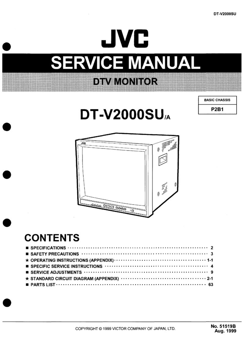
CONTENTS
IB
SPECIFICATIONS:
“cc
ecusetuncieaee
tines
sete
newsiews
is
Suaewemcariacdugatuaharte
2
Mi
SAFETY
PRECAUTIONS
........0
2.0000
c
cece
cece
nent
eee
e
eee
ees
iDineat
onc
ens
3
I
OPERATING
INSTHUGTIONS
caucus
ce
oss
vx
care
iis
errs
nea
areal
a
weet
Seances
4
M.
SPECIFIC:
SERVICE
INSTRUCTIONS:
2
f05
ccccea
cds
ey
oven
ste
Mo
eunacds
abi
aeasuncbeny4
8
B-SERVICE
ADUJUSTMENTS...,a.5:ic
nonce
odes
Reinoieeina
ence
ae
od
bases
4
Sioa
aie
He
11
M
PARTSLIST
...........
Rh
aco
elaine
inte
Rca
hana
ihc
alin
Sng
tami
eat
Moa
ahie
19
M
SCHEMATIC
DIAGRAM(APPENDED)
.........0-
20-0
e
cece cece
cece
eect
ee
tenes
O~®
No.50343
COPYRIGHT
©
1989
VICTOR
COMPANY
OF
JAPAN,LTD.
Dec.1989
TM-1500PS
|
SPECIFICATIONS
Dimensions
Weight
Color
system
Power
input
Power
consumption
Picture
Tube
Screen
Size
Scanning
frequency
High
voltage
Horizontal
resolution
Speaker
Audio
output
INPUT
A
INPUT
B
Y/C
INPUT
ACCESSORY
OPTION
FUSE
2
(No.50343)
36.0cm(W)
x
39.4cm(D)
x
33.4cm(H)
16.0kg
PAL/SECAM
system
AC
220
-
240V,50/60Hz
Max.
68W
15”(measured
diagonally),90°
deflection,in-Line
gun,data
grade
tinted
CRT
tri-dot
pitch
0.499mm
284mm(W)
x
213mm(H)
(H)
15.625KHz
(V)
50Hz
24kV(at
zero
beam
current)
More
than
450
lines
4.5cm
round(16Q)
x 1
0.75W
BNC
x
2(IN/OUT),Bridged
connection
is
possible.
VS-1Vp-p,75Q,negative
A
termination
switch
is
provided.(75Q2/OPEN)
RCA
pin
connector
x
2(IN/OUT),Bridged
connection
is
possible.
390mVrms,High
impedance
8-pin
connector
x
1
VS-1Vp-p,752Q,negative
775mVrms,High
impedance
7-pin
connector
x
2(IN/OUT),Bridged
connection
is
possible.
Y-VS-1Vp-p,75Q,negative
C-0.3Vp-p(burst),75Q
A
termination
switch
is
provided.(75Q/OPEN)
RCA
pin
connector
x
2(IN/OUT),Bridged
connection
is
possible.
390mVrms,High
impedance
Power
cord(approx.
2.4m)
x
1
RK-150E(RACK
MOUNT
ADOPTOR)
QMF51E2-3R15S
(3.15A)
Design
&
specification
subject
to
change
without
notice.
SAFETY
PRECAUTIONS
The
design
of
this
product
contains
special
hardware,
many
circuits
and
components
specially
for
safety
purposes.
For
continued
protection,
no
changes
should
be
made
to
the
original
design
unless
authorized
in
writing
by
the
manufactur-
er.
Replacement
parts
must
be
identical
to
those
used
in
the
original
circuits.
Service
should
be
performed
by
qualified
per-
sonnel
only.
Alterations
of
the
design
or
circuitry
of
the
products
should
not
be
made.
Any
design
alterations
or
additions
will
void
the
manufacturer's
warranty
and
will
further
relieve
the
manufac-
turer
of
responsibility
for
personal
injury
or
property
damage
resulting
therefrom.
Many
electrical
and
mechanical
parts
in
the
products
have
special
safety-related
characteristics.
These
characteristics
are
often
not
evident
from
visual
inspection
nor
can
the
protection
afforded
by
them
necessarily
be
obtained
by
using
replace-
ment
components
rated
for
higher
voltage,
wattage,
etc.
Re-
placement
parts
which
have
these
special
safety
characteris-
tics
are
identified
in
the
parts
list
of
Service
manual.
Electri-
cal
components
having
such
features
are
identified
by
shading
on
the
schematics
and
by
(
4\)on
the
parts
list
in
Service
manual.
The
use
of
a
substitute
replacement
which
does
not
have
the
same
safety
characteristics
as
the
recommended
replacement
part
shown
in
the
parts
list
of
Ser-
vice
manual
many
create
shock,
fire,
or
other
hazards.
Don’t
short
between
the
LIVE
side
ground
and
NEU-
TRAL
side
grounding
or
EARTH
side
ground
when
re-
pairing.
Some
model’s
power
Circuit
is
partly
different
in
the
GND.
The
difference
of
the
GND
is
shown
by
the
LIVE
(1)
side
GND,
the
NEUTRAL(
»-)
side
GND
and
EARTH
(
®)
side
GND.
Don’t
short
between
the
LIVE
side
GND
and
NEUTRAL
side
GND
or
EARTH
side
GND
and
never
measure
with
a
mea-
suring
apparatus
(oscilloscope
etc.)
the
LIVE
side
GND
and
NEUTRAL
side
GND
or
EARTH
side
GND
at
the
same
time.
if
above
note
will
not
be
kept,
a
fuse
or
any
parts
will
be
broken.
lf
any
repair
has
been
made
to
the
chassis,
it
is
recommended
that
the
B1
setting
should
be
checked
or
adjusted
(See
AD-
JUSTMENT
OF
B,
POWER
SUPPLY).
The
high
voltage
applied
to
the
picture
tube
must
conform
with
that
specified
in
Service
manual.
Excessive
high
voltage
can
cause
an
increase
in
X-Ray
emission,
arcing
and
possible
component
damage,
therefore
operation
under
excessive
high
voltage
conditions
should
be
kept
to
a
minimum,
or
should
be
prevented.
If
severe
arcing
occurs,
remove
the
AC
power
im-
mediately
and
determine
the
cause
by
visual
inspection
(incor-
rect
installation,
cracked
or
melted
high
voltage
harness,
poor
soldering,
etc.).
To
maintain
the
proper
minimum
level
of
soft
X-Ray
emission,
components
in
the
high
voltage
circuitry
in-
cluding
the
picture
tube
must
be
the
exact
replacements
or
al-
ternatives
approvided
by
the
manufacturer
of
the
complete
product.
Do
not
check
high
voltage
by
drawing
an
arc.
Use
a
high
volt-
age
meter
or
a
high
voltage
probe
with
a
VTVM.
Discharge
the
picture
tube
before
attempting
meter
connection,
by
con-
necting
a
clip
lead
to
the
ground
frame
and
connecting
the
other
end
of
the
lead
through
a
10kQ
2W
resistor
to
the
an-
ode
button.
When
service
is
required,
observe
the
original
lead
dress.
Ex-
tra
precaution
should
be
given
to
assure
correct
lead
dress
in
the
high
voltage
circuit
area.
Where
a
short
circuit
has
oc-
curred,
those
components
that
indicate
evidence
of
overheat-
ing
should
be
replaced.
Always
use
the
manufacturer's
re-
placement
components.
9.
(1)
(2)
|
TM-1500PS
Isolation
Check
(Safety
for
Electrical
Shock
Hazard)
After
re-assembling
the
product,
always
perform
an
isolation
check
on
the
exposed
metal
parts
of
the
cabinet
(antenna
ter-
minals,
video/audio
input
and
output
terminals,
Control
knobs,
metal
cabinet,
screwheads,
earphone
jack,
control
shafts,
etc.)
to
be
sure
the
product
is
safe
to
operate
without
danger
of
electrical
shock.
Dielectric
Strength
Test
The
isolation
between
the
AC
primary
circuit
and
all
metal
parts
exposed
to
the
user,
particularly
any
exposed
metal
part
having
a
return
path
to
the
chassis
should
withstand
a
voltage
of
3000V
AC
(r.m.s.)
for
a
period
of
one
second.
(...
.
Withstand
a
voltage
of
1100V
AC
(r.m.s.)
to
an
appli-
ance
rated
up
to
120V,
and
3000V
AC
(r.m.s.)
to
an
appli-
ance
rated
200V
or
more,
for
a
period
of
one
second.)
This
method
of
test
requires
a
test
equipment
not
generally
found
in
the
service
trade.
Leakage
Current
Check
Plug
the
AC
line
cord
directly
into
the
AC
outlet
(do
not
use
a
line
isolation
transformer
during
this
check.)
Using
a
"Leakage
Current
Tester”,
measure
the
leakage
current
from
each
ex-
posed
metal
part
of
the
cabinet,
particularly
any
exposed
metal
part
having
a
return
path
to
the
chassis,
to
a
known
good
earth
ground
(water
pipe,
etc.).
Any
leakage
current
must
not
exceed
0.5mA
AC
(r.m.s.).
©
Alternate
Check
Method
:
Plug
the
AC
line
cord
directly
into
the
AC
outlet
(do
not
use
a
line
isolation
transformer
during
this
check.).
Use
an
AC
volt-
meter
having
1,000
ohms
per
volt
or
more
sensitivity
in
the
following
manner.
Connect
a
1,5002
10W
resistor
paralleled
by
a
0.15pF
AC-type
capacitor
between
an
exposed
metal
part
and
a
known
good
earth
ground
(water
pipe,
etc.).
Mea-
sure
the
AC
voltage
across
the
resistor
with
the
AC
voltmeter.
Move
the
resistor
connection
to
each
exposed
metal
part,
par-
ticularly
any
exposed
metal
part
having
a
return
path
to
the
chassis,
and
measure
the
AC
voltage
across
the
resistor.
Now,
reverse
the
plug
in
the
AC
outlet
and
repeat
each
mea-
surement,
Any
voltage
measured
must
not
exceed
0.35V
AC
(r.m.s.).
This
corresponds
to
0.5MA
AC
(r.m.s.).
AC
VOLTMETER
(HAVING
10002/V,
OR
MORE
SENSITIVITY)
PLACE
THIS
PROBE
ON
EACH
EXPOSED
METAL
PART
i
15002
10W
GOOD
EARTH
GROUND
Fig.A
(No.50343)
3
TM-1500PS
OPERATING
INSTRUCTIONS
YNATNOD
O3CIA
HNALINOW
‘SNOILONYLSNI.G
TANNVAW
YOLINOW-O23dIA-8¥v4
‘ONNLIFINVSONNNIIGIE
YOLINOW
OACIA
YHNOTOD
SdOOSH-WL
JAP
SNOLLONYLSNI
“angsd
sues
sejqezsipous
sonbdssjsp)
20200
Je
VORMUEPIS
(ww
:4Un)
SUOPsUeUIG
1
x
(Wi
p’Z
Udaaue)
UOPMUEUH|e,P
UOPs0D
:
esjorseaoty
64
0'OL:
Spied
“eqissod
Opuos
Ue
JUOWepIO9De,
‘aouBpedtU)
mney
‘suuAW
O6E
—
CIANV
("nagud
380
92/WUp2)Xe,p
Une
eyMMUWOD
Py)
‘BIG
IS8Od
epUOS
UB
LUEWAPJODORY
swyo
gf
"(381Ng)
9A
£0
—
9
eaye6gu
O4YOUAS
‘sULYO
Ge
‘DOA
|
—
A
Z
XO/A
S0Yd0Iq
£
@
INBOQUUOD
:
WA
LNNI
eousppduy)
ayney
‘suuAWw
G/Z
-
OIGNV
eapespu
OsyOUAs
‘sUIYO
GZ
‘SOA
|
—
SA
1
X
$84y902q
g
UN@JDQUUOD
|
BANdNI
“aqyssod
@pUcs
Ue
JUsWEp/ODNR
‘eoUEpgdUt
arney
‘su
Aw
OBE
‘Z
X
VOU
$o1j901q
§
4NeJD0ULOD
—
OIGNY
(‘nagid
180
92]UUPAIX8,p
INBIBINUWWWOS
UN)
“ajqjssod
Opucs
Us
JUsWepsoooR,
‘eApeipu
Osyouds
‘suyo
GZ
'99A
L
~
SA
ZX
ONG
—
O3QIA:
Vv
LNdNI
MSO
*XEW
:
uopewwosED
7H
09/09
‘VO
A
Ove
—
022
:
uopeuewliy
s0uB!t
OG
op
sNjg
:
eMUOZHOY
LOP
NCSI
2H
09
(A)
2H
SZO'SL
(H)
*
eBeAejeq
op
sousnbps4
WW
ELZ
X
PBZ
+
(AXH)
UbIOP,
Op
Oe,
|
X
wo
Q’p
op
puoy
:
dneped-ney
MsZ'0:
opne
epics
wwg6P'0
89/014
Quod
Sop
si//0)
“Opesd-wiep
9yUje)
‘ouby)
US
$U02399/9
@
sUuOdUeD
‘
‘906
OP
UO!
EIAPP
"{ejeuoBelp
Us
gansaw)
wd
gE
:
oBewy
oqny
WV93S/TVd
:
dnejnos
ewgsds
$04002q
Sep
UORFIDEY
be
1NB{NOD
OgplA
INeHUOW
:
edAL
SANDINHDAL
SANDILSIYALOVYVD
4
(No.50343)
TM-1500PS
“yUN
siyy
JO
esodsjp
02
;aUUOSIEd
BO]AZ8S
P'
ASy
“"VOISO;dUy
eqn}
eunyajd
e@
Uy
INse1
P]NOD
jesodsip
sodosdus}
‘851j
|NJASN
$)]
JO
PUBS
GUT
SayORO!
HUN
S142
VOU,
“BINJOsOI]
GOJAUSS
$,JOINIDe;NUSW
BY}
Uy)
PEqLOsSeP
yOoYD
Ajazes
Oy)
LUI0J
10d
0}
oUUIOSIEd
BO]ALES
BY)
488
oseeld
"yun
sya
02
syedes
40
Bufojases
Aue
yo
UOoTejdwos
uodr
*$pseZey
J0YIO
20
‘HOOYS
‘01})
3UBA
-gid
uso
syed
yuatUede;des
paljioeds
s,s9sNJOBJNUBL
JO
BSF)
“shied
jeusBy10
ayd
s@
sops[iezosseyo
Ayejes
Owes
O43
GACY
S@sN
ay
syed
yUswWadE|das
ayd
yeYy
GussM
UY
AjpBA
JoUUOS
«18d
sOJAsas
BYY
GACY
‘PastNbas
Ble
sysed
yUEWEdE|dar
VOY
*jouuosied
aO1AUes
PapWeENb
Oy
Bulojasos
19301
SAeMiy
‘spueZeY
J9IPO
40
968}j0A
snozeBuep
03
NOA
asodxe
Aew
sieA0d
Buyaowas
JO
Buiuado
se
4)asiNOA
YUN
siyy
aajAsas
OF
JdWeTe
OU
Od
“eoue
“W1Ojed
Ul
aBueYd
JOUNSIP
SHqIYXe
IjUN
ey.
VOY
~
“pebewep
uaaqg
sey
youlqes
ey
20
peddoup
ueaq
sey
wun
ey
4)
—
‘suononsisu!
Bunese
-do
ayy
Buimojjos
Ajjeusou
eyeado
JOU
sSeOP
JUN
Ayr
4]
"MUN
EY)
OIU!
Paljds
Uaeq
sey
PINdI|
|
“pabewep
s}
Bnd
10
pede.
3)
Ps0d
samod
ey
UayYM
—
sSuOp{pUoD
GulMo}jOy
ayy
sapUN
jauUOsied
so)AIes
Palji}ENnb
185
JOJOs
PUB
JO|INO
Dy
ayy
wor
YUN
si4ys
Sniduy
“LOD
340s
@
YIM
Ueajd
‘2OeRjINS
UGIIDS
O42
UO
SOJejNUINIOV
ISNP
UUM
*UONEINUGA
pasynbez
By)
39N43sqGO
P[NCd
Sly)
$@
UONe1adO
UF
a]1YM
SIO}$
UO]JE{NUEA
ly
JeACD
JOU
OG
*seneid
payeynuean
Ajpeg
uy
—
pue
‘24B1yuNs
yasp
0}
yalqns
seoeid
Uy
—
‘spjaly
JRaubew
Bu0s
GBuesaueb
seoueydde
sweeu
—
‘seonjd
Aysnp
uy
—
*sane(d
plwNy
40
Pjoo
“yoy
Ajewesjxe
uy
—
:SU0{31PUOS
Bujmo]jO)
eyy
sapUN
yyUN
Siu)
BuysN
ploay
*yOOys
911399)3
JO
a2jy
@
Ul
INSOd
Ued
S1YI
SE
SP10D
1aMOd
JO
S2E;yNO
{IBM
PEO|J@AO
JOU
0G
“Ps0d
eY3
UO
Peal)
{1M
ejdoed
alayM
UN
$143
03890]
JOU
Op
pury
‘p09
seMod
ay}
UO
yse1
0}
BulysAUe
MO[je
JOU
OG
“ypno
oy
ays
wos;
Bnjd
semod
ey)
JeUUODSIP
0}
ans
oq
‘31
BuyUeaD
UaYA
JO
‘aU
4O
poyed
BuO}
@
304
YUN
sI4y)
GuIsN
JOU
UY
*JOUIGED
eYr
JO
1823
UO
Pa}e00j
jeqe]
Buyer
eyy
uO
pajjzjoads
sounos
samod
ayy
AjyO
asf
SNOILNVO3Yd
“payezedo
eq
se6u0}
Ou
es0jos01n
ysNW
Pue
‘uorea11400
yO
spsspuels
o1p
syeow
106U0)
OU
AEM
@
YONs
U)
Peserje
BUN
Yy
‘esOP
BIQeZepP}sUOd
4O
VO)ss}Wa
Aes-xX
Uy
3jnses
ABW
aqny
jo
BGA,
ein
BuyBueyo
10
08€3)0A
uBiy
jO
YoONnese
JeINIQIed
Uy
‘sUO}e1edo
sedosdW)
*plasanoA
yy
aarases
0}
As)
soAaRY
“JeUUOSIEd
SOJAJesS
Petj{jenb
yoeUOd
‘sOIUOW
sip
BuyojAses
USUM
“JOUIGED
OI
JO
J9AOD
ADEQ
OY}
GAOWOI
JOU
OG
‘HUN
ayy
episu
iuesesd
ase
seBexjoA
yojy
snosebueg
“BINSJOW
JO
Ujes
OF
JO}
UOW
sii
asodxe
10%
Op
‘puezey
xOOYs
JO
a1
JUBASAD
Of
|
SONINUYM
“suonnesoid
Bu;
-AA0}J0}4
84
JIB
JO
B2eMe
Ajl]Ny
oq
‘20j}UOW
aif
yo
BuypUBYs}W
40
uopesedosjw
Aq
pasnes
sjuapyooe
(eye,
Aue
jusAesd
03
10ps0
Uj
NO
sUuosOBULOD
*
{jouedg
1804)
+++»
(eueg
3u01g}
$10}90UU09
PUB
$};02U0D
“*
suopnedasg
Apeyes
SLNALNOD
oOo
SNONO
Ul
SUONONYSU
[je
PEs
aseajd
‘e}1)
Bd[AJes
S}}
PUBIXe
O}
PUB
10}}UOU
B'
{'309b-1U
etp
JO
jenuew
VORoNss
U}
if
0}
49j01
‘BuUMOW
204)
‘3094-1U
2eidepe
yunoWw
yoes
jeuondo
yim
oe
WIR
PsepUNIs
B
Ul
sIqeUNOW
“220
‘YOR
IMS
$8029
asind
‘YonIMs
UBS
Jopun
@
BupNjauy
sussn
jeuolssejosd
Aq
pesjnbes
sepyoey
snouawnU
yA
A1IIqQIxXe))
sJOedNs
PUB
UOPOUNY-INW
“s0u}|
OGP
URLB
e10lU
40
LOL
NOSe
eRUOT}OY
B
IpIM
sesNJojd
20)
49241
Quod
@
qBIM
JeYpeBO.
“LHD
epeb-mep
Youl-gi
"yNdu]
CePA
eyesedes
D/A
‘Q@PJA
ezjs0dwWOD
Buydeose
‘suo)edidde
jeudjsse;
-O1d
jo
e6ues
OPM
@
40)
AIjQIEdWIOD
PrEpUeIs-pjNYy
Saunlvas
"@0U810404
GNM)
JO}
98/0
ayes
@
Ul
3)
deay
PUB
30;400q
s]Lp
ua
yO
Bujpueysuepun
a2e)dWOd
@
ainsus
Of
“sUO}JOUNY
(Njasn
AUB
sejesOdiooU!
pue
senyaid
Ajienb-sol4adns
eplAodd
j)JM
JON
UOW
AAU
UNDA
“4O}}UOW
OAP{A
ANOjOD
JAP
&
Buyseyound
Joy
MOA
yueyL
To)
oO
¥
ee)
3S
ie
fe]
=
TM-1500PS
apo
jeUON
:
TWIAHON
{lue}sU0d
aw)
18]jeWS)
Epo
Isey
:
isv4
“a’NQDId
ay?
4O
UONIOd
peMays
ayy
3901/00
0}
ANINoU}O
SUAS
JeJUOZ}JOY
BY
JO
YwWRISUOD
ay
DAY
eYy
Sa4dIIMS
YRIMs
IV
“AIUO
j@UUOSAd
Bd}AI2s
205
$f 3)
"YOIIMS
S12
JOSA1
JOU
OG
YOUMS
dN
LIS@
ANNI
D/A
{'93@
pus
“EE99/A
“BZ8D/A°
“ENG)}
ss01DeUUOS
Bulqqnp
49430
ep
02
psyooUU0D
0
YOUU
Ao
HLA
OUa
JO
S10}08UU0S
EYbD/A
By}
0}
peyD9UU0D
eq
AjUO
UBD
sJOJIeULIOD
esey)
:UO;INED
wo};29UU0D
pebpy7q
104:
N3dO
syeuBys
induy
Ajuo
ee
e1ey
UBUM:
342
YOnMs
uoyeujuse
ein
Bunes
uopseuUuos
pe6piiq
JO4
>
INO
syeuBys
Bupinduy
vey
:
NI
*sjeuBys
payaeuUOd-e6py1q
40}
$10398UU09
INd\No
pus
sjeuBys
o1pne
pue
Cepia
ayesedes
D/A
105
S20,98UUID
yNduU)
YOUIMs
UO]
BU}W4e
|
/840}98UU09
LNdNI
D/A
@
*s0}99UU0D
INdINO
HLA
uid-g
yo
adA}
owes
ayy
yim
Papfaoud
s}
yey.
yUaUUdinba
WOsy
sjeUuB]s
O[PNe
NUE
OEPIA
03}SOdWOD
404
10}D9ULIOD
Indu}
40}98UL09
g
LNdNI@®
uOReuUOS
pebplg
104
:
N32dO0
jeuBis
yndut
ue
Ajuo
$)
ssay,
UUM:
USL
YAS
UOPeUswWe)
ey
BUNIES
uofideuUo0d
pebpyigq
104:
1NO
yeuB}s
@
Buninduy
usyA
:
NI
*sj@uBys
pe,2euU0d-96p}2q
10}
$10399UU02
yNd3Nno
pues
sjeu6ys
OIpne
Pues
OepjA
aijsodwod
40;
s:0}98UL09
Indu)
YOUIMS
UONBU;
WHO]
/$10}90UU0D
Y
LNdNI@®
"P109
JeMOd
PapjAosd
ays
YIM
3e/}NO
Oly
UB
OY
YOaUUOD,
40}
99UU09
gnduy
48Mog
@
(joueg
1e04y)
-9-
*J04,U09
S}4yX
YOND)
JOU
Og
“AJUO
[BULOSIOd
BOtAIOS
104
8]
SHG)
102U09
YWOHHI
ENS
Ivd
@
*#JO
8008
s0180;pu)
Ys
°yj0
semod
eys
suzny
Uyebe
Yyorms
siya
Guyssezg
*946]]
JOYed|puy
ayy
‘UO
seMOd
ay.
suuMy
YyoYMs
sy
Burssesg
403
80/PUI/YRIMS
HIMOd
@
*sseujyBiiq
pue
Aysuep
ewes
ay)
GARY
$48q
ONIq
{18
JEU)
OS
Jonu0d
WWOHHD
84s
WNL
(z)
aimayd
eniq
ewsosysouow
@
Agjdsip
©}
jeu8ys
4eq
uNOjoo
ayy
anduy
{4)
eunpesoid
Bunsnipy
sanyojd
eng
awoyoOUOW
:
|
~
}
einjojd
jewWON:
(we)
“VWOHHD
ey
Bun
snipe
pue
Buyyo9Y49
404
‘eniq
aWOJYsOUOW
PUe
jeWOU
UsaMieq
eumojd
ayy
seYyoMS
YRIMS
HOIHD
ANIA
@
@1NYIjd
BWOIYIOUOW
@
4104:
{—
}
eimod
unojooe
104:
(wr)
“930
‘eouRjeq
a3;4yM
Bulyseyo
40}
BWIOLYOOUOW
PUe
INOjOD
UBAaMjeq
aINjZ21d
seYyoIMS
$8903
482q
Bue
Aysuep
swes
Tf
Yims
440
HNO109
O
a
|
Aegjdsip
yoa49
fe
Z,
pojied
08301
104:
(~~)
NO
|
|
eantojd
yewou
404
>
(
we)
440
WA
“jeuB)s
ynduy
ap
yo
aseyd
ain
BuyAeyap
Aq
(jeubis
DUAS)
Poyied
ade1301
BY
YOeYD
OL
YUMS
SSOUD
ASINd
@
Bujuueosiapun
40)
>
(=)
Bujuueosiero
105:
(we)
“U8|19$
OY)
UO
Oz1s
BUsUUBDS
OLN
LOIIMS
0}
SSOLq
yous
NYS
HIGNN
©
A
wvoaS
ar
10390UU09
g
Ld
“NI
Stp
@)A
jeubls
@
Buoyuow
ueUM
:
{<)@
40}98UU09
YW
Lfid
“N)
91p
G14
jeuBls
e
BuyojjuoW
Ua
:
iwiv
‘uo
isod
g
10
y
03
24y2
GIP
UO
YorIMS
243
388
“OSGIA,
OF
Yims
Yo}
a4r
Bupes
a1UM
{z)
{{eued
se0,
@UA
UO
40}99UUOD
LAdNI
D/A
OU
BIA)
syeuBys
Oapla
ayesedas
9/4
Buroyuow
UsYy
:
(joued
4892
a4)
UO
JOJDeU
oo
@
LAGNI
40
VY
LOGNI
ef
eA)
teub)s
OapjA
aysodwos
e
BuyoyuoW
UeUM
:
(
we)
OAGIA
‘uoNssod
9/A
40
OAQIA
OF
248]
843
UO
Yorims
OL
29S
(1)
(s18ubjs
ou
Sup
copes)
*$10}D9UUI0D
188d
BY
03
INUY
sjeUNB}s
CAPA
OLA
398}08
0}
ssa
SOUTIMS
1979S
LNINI@
WaIsAs
1NO}OD
WYDRS
404
:
(=
)
NVO3S
wajysds
INDjOO
Wq
404:
=
(we)
TW
“NGuy
$1
jeUBls
O@plA
B
UBYM
WAySAS
INOIOD
ayy
SEYDIIMS
YRIMS
WALSAS
@
*89U810,010
INOA
0}
38813U09
ouNdI}d
aLp
IsN{pe
OF
WIN)
f0QUu0d
ISVYHLNOD
@
*e0Ue20J01d
INOA
0}
ssaurYyByIq
aINjo}d
aLp
ysN{pe
OF
WIN,
e3uU00
LHDOING
©
“aquasajosd
ANOA
0}
@4NQII
ay
4O
AXjsUEP
INOJOD
sip
YsN{pe
02
VINE
P09
YWOHHSD
©
*sjoquoo
ANS
842
UN
0}
seALIPM|LNS
&
BS/)
“$]042UOD
ALA
JO
ays
OL
2@
SMAI9S
0JJUOD
GNS
94)
BuyusM
Aq
(Jesesd)
PolzeA
eq
UD
Bunres
puspueys
s142
‘Bues
psepuErs
9)
$}
fOAIUOD
YORE
JO
UO}NSOd
49}}9
enUAD
ay)
‘euNd!d
aLp
eZJWIdO
©}
os/)
$]0QU09
Bind
@
(~~)
O/A
“4O1JOS
2}
OHBW
0}
OSIM
+490/0J03UN0D
“4opNO]
PUNOS
aif
aXAW
02
OS{MxOO/D
UNL
{0U09
AWNT1OA
@
“aaMajd
ay
4O
VOREZUOIYIUAS
jRONIEA
OL
IsN[pe
OF
LUN)
102009
10H
‘A
@
7)
i
0
oS
po
{oe}
=
—
©
TM-1500PS
*N3dO,,
OF
YOIJMs
UONBU;WIO2
#9]
19s
‘(andyno
peBipisq)
ssoyoeuUOS
470
943
4O
Aue
Bulsn
Wau
@
J0.JUOW
COPIA
40}UOW
COp]A
@JO8U09 jO2.U0D
INdanosinduy
COPIA
eresedes
O/\
ino
NE
UL
oranv
—
use
(EO
J}N3e0
1NO—
D/A
m—-
NI
ino
Nt
.
o1anv-—
uac(EPT
Nao
@
LAANI
WUMs
1939738
LNdNI
indjnopnduy
COPIA
e2}p0dWOD
COPIA
“peed.
oq,
0}
queWINbe
ayy
40
jBNUBW
LOWONNSU!
GY}
0}
10401
OSiy
@
“quadjnbe
28430
0%
BuyoouUOd
81050q,
WpNO
Dy
sys
wos
Bnd
seMod
ayy
OeULODS|P
0}
GINS
Og
©
“wesBelp
yNdsfo
&
OU
$}
3)
‘sy¥deDU09
Bu;moys
‘sUOPIeUUOD
PUe
AjyNDII9
Alp
JO
BUIPNE
Ue
sj
BuJMO]{Oy
BULL
WVHYDVIC
ANITLNO
SNOLLOANNOO
SNOILOSNNOO
(No.50343)
7
TM-1500PS
|
SPECIFIC
SERVICE
INSTRUCTIONS
DISASSEMBLY
PROCEDURE
1.
Method
of
removing
the
top
cover
(1)
(2)
(3)
Remove
the
two
screws
©
in
Fig.
1.
Remove
the
respectively
two
screws
©
and
©.
By
pulling
the
cover
a
little
bit
backward,
dismount
the
cover
as
indicated
by
an
arrow.
Method
of
dismounting
the
rear
cover
e
(1)
(2)
Dismount
the
top
cover.
Remove
the
two
screws
©
in
Fig.
2-1.
Pull
the
rear
cover
right
upward
until
it
stops
as
indicated
by
the
arrow,
and
dismount
the
cover.
For
assembly,
(1)
Since
the
four
positions
©
in
Fig.
2-2
are
hooked,
align
the
hooks
straight
and
let
them
move
down.
8
(No.50343)
gee|
Also
remove
the
screw
on
the
opposite
side.
Fig.
1
7)
STOUANUGULESTPUHAGOESOGETUAGEELESTD
3.
Method
of
dismounting
Input
PCB
@
Dismount
the
top
cover.
¢
Dismount
the
rear
cover.
(1)
Remove
the
three
screws
©
in
Fig.
3.
(2)
Remove
the
GND
wire.
(3)
When
the
two
hooks
between
the
Main
and
Input
PCBs
are
removed,
the
Input
PCB
will
be
dismounted.
(4)
Dismount
the
connectors,
etc.
as
required.
Method
of
dismounting
Power
PCB
@
Dismount
the
top
cover.
(1)
Remove
the
wire
clamp
fixing
the
transformer
on
the
Power
PCB
and
PCB
holder.
(2)
Remove
the
four
screws
©
in
Fig.
4
and
dismount
the
PCB
holder.
(3)
Remove
the
two
screws
©.
(4)
After
raising
the
Power
PCB
once,
pull
the
lower
part
of
the
PCB
outward
and
dismount
the
PCB.
(5)
Dismount
the
connectors,
etc.
as
required.
Method
of
checking
the
Main
PCB
¢
Dismount
the
top
cover.
e
Dismount
the
rear
cover.
(1)
Set
the
TV
set
sideways
as
shown
in
Fig.
5.
In
this
case,
lay
soft
cloth,
etc.
under
the
set
in
advance
to
prevent
any
damage
to
the
exterior
part.
(2)
Remove
the
four
screws
@
and
dismount
the
bottom
lid.
(3)
Shift
the
Main
PCB
as
required.
|
TM-1500PS
CO
TD
TOGUEGUUCTUNGHEAUU
ASTON
EL
DEADA
TDG
TUATHA
oO
fe) fe)
Oo
UADUDATAAEAUAUTA
TG
SEELUTD
ERGY
Fig.
5
(Bottom
surface
view)
(No.50343)
9
|
TM-1500PS
|
6.
Method
of
dismounting
front
panel ass’y
e
e
(1)
(2)
(3)
(4)
(5)
(6)
Dismount
the
top
cover.
Dismount
the
rear
cover.
Remove
the
speaker
chord
(Main
PCB
[G]).
Remove
the
chord
of
degauss
coil
(Power
PCB
[I]).
Remove
the
two
chords
of
deflecting
coil
(Main
PCBs
[H]
and
[V}).
Remove
the
anode
cap.
Pay
attention
to
the
high
tension!
Since
the
cap
will
be
electrified,
be
sure
to
remove
the
cap
after
discharging.
After
removing
the
(CRT
EARTH]
chord,
pull
out
the
CRT
socket
PCB.
When
the
four
screws
@
are
removed,
the
front
panel
ass’y
will
be
dismounted
together
with
the
CRT.
@Since
the
CRT
is
heavy,
remove
the
screws
@
while
holding
the
front
panel
ass'y.
7.
Method
of
dismounting
speakers
e
°
°
(1)
(2)
Dismount
the
top
cover.
Dismount
the
rear
cover.
Dismount
the
front
panel
ass’y.
Remove
the
speaker
chord
(Main
PCB
[G)).
Remove
the
two
screws
fixing
the
speaker
to
the
front
panel
ass’y.
e@Unless
the
front
panel ass’y
has
been
dismounted
from
the
TV
set
body,
it
is
impossible
to
mount
the
speaker.
8.
Precautions
for
wire
clamp
and
binding
band
(1)
The
wire
should
be
clamped
exactly.
(2)
Be
sure
not
to
remove
the
binding
band
for
wire
treatment.
Should
it
be
removed,
the
wire
should
be
treated
exactly
to
the
initial
position.
10
(No.50343)
Chord
of
degauss
coil
Anode
cap
Pay
attention
to
high
Speaker
chord
tension!
Chord
of
deflecting
coil
Fig.
6-1
Use
the
long
screw
driver.
The
screw
driver
is
accessible
from
here.
Fig.
6-2
}
4
TM-1500PS
SERVICE
ADJUSTMENTS
TOOLS
AND
FIXTURES
FOR
ADJUSTMENT
PRIOR
TO
STARTING
ADJUSTMENT
@
Dismount
the
top
cover,
rear
cover
and
bottom
lid.
@
Perform
sufficient
warm-up
of
the
TV
set
and
testers.
(for
30
minutes
or
more).
@
Unless
specified
otherwise
specially
in
[ADJUSTING
STEP]
given
below,
perform
adjustment
after
setting
the
switches
and
VRs
on
the
front
panel
to
the
following
-positions:
BLUE
CHECK
:
OFF
COLOUR
OFF
:
OFF
PULSE
CROSS:
OFF
UNDER
SCAN
:
OFF
SYSTEM
SW
:
PAL
INPUT
SELECT
:
VIDEOA
CONTRAST
:
CLICK
position
BRIGHT
:
CLICK
position
CHROMA
:
CLICK
position
PHASE
:
CLICK
position
@
Regarding
the
list
of
the
layout
of
adjusted
parts,
refer
to
[ADJUSTMENT
LOCATION]
in
[SCHEMATIC
DIAGRAM}.
ADJUSTING
STEP
POWER
PCB
DC
voltmeter
or
digital
voltmeter
Oscilloscope
Pattern
generator
(PAL)
-
If
monoscope
signal
can
be
output,
it
is
possible
to
perform
further
accurate
adjustment.
-
The
signal
should
be
input
to
VIDEO
A.
Color
thermometer
-
Adjustment
is
possible
without
it.
If
available,
however,
further
accurate
adjustment
is
possible.
Short
jumper
10kQ
resistor
In
addition
to
the
above,
the
following
tools
are
necessary
to
adjust
the
purity
and
convergence.
Magnetic
eraser
Silicon
bond
(KE4866)
REICHLOCK
or
G2
bond
Measuring
Adjustment
PATTERN
GENERATOR
Adjustment
of
B1
VOLTAGE
R913(B1
DC
VOLTMETER
or
DIGITAL
VOLTMETER
POWER
PCB
ADJUSTMENT)
|
2.
.
Input
the
total
black
signal.
Adjust
the
B1
adjust
VR
(R913)
so
that
the
voltage
between
TP-91
and
TP-E
(7-)
becomes
DC
110V.
.
Confirm
that
the
B1
voltage
scarcely
changes
even
when
the
input
signal
has
been
changed.
(No.50343)
11
TM-1
500PS
MAIN
PCB
(1)
Measuring
Adjustment
Adjustment
of
PATTERN
TP-40
.
Input
the
color
bar
signal.
PAL
APC
GENERATOR
1C301
14Pin
Connect
1C301
14Pin
and
TP-E
with
a
short
jumper.
TP-92
Connect
TP-40
and
TP-92
with
a
10k2
resistor.
SHORT
JUMPER
|
TP-E
Adjust
the
COLOR
SYNC.
VR
(C320)
to
a
position
,
where
the
color
changes
from
a
striped
pattern
to
a
color
bar
and
remains
at
a
standstill.
5.
Connect
the
oscilloscope
to
TP-48
and
TP-49,and
plot
the
X-Y
coordinates.
6.
Adjust
with
R323
and
R332,C331
so
that
the
waveforms
are
the
shapes
shown
from
A
to
B
in
the
chart
below.
SEO
LX
.
When
it
is
not
possible
to
adjust
with
the
two
VRs,adjust
with
C339.
8.
Input
the
half
color
bar.
9.
Adjust
with
C320
so
that
the
color
at
the
center
section
under
the
color
bar
is
at
minimum.
ae,
(DL
AMP)
C332
PONS
10
k2
RESISTOR
Oo
a
0
0155%°
m
cas9
@
8
C332
@
TP-92
C3298
C331
@TP-EO
O
Adjustment
of
PATTERN
NOCTH
CIRCUIT
|
GENERATOR
TP-64
(Y)
1.
Input
the
color
bar
signal.
2.
Connect
the
oscilloscope
between
TP-64
and
TP-E.
in
case
the
waveform
can
be
expanded
by
the
oscilloscope,
expand
the
waveform
to
allow
easy
adjustment.
3.
Adjust
the
C236
so
that
the
CHROMA
component
becomes
minimum.
OSCILLOSCOPE
Minimize
the
CHROMA
component
Expansion
of
waveform
12
(No.50343)
|
TM-1500PS
Continue
running
for
10
minutes
or
more.
CRT
socket
PCB
Measuring
:
Adjustment
PATTERN
R705
:R
Adjustment
of
CUTOFF
GENERATOR
R715
:G
1.
Input
the
total
white
signal.
R725
:B
2.
Turn
the
transverse
one
line
[SET
UP]
switch
(S203)
SCREEN
VR
on
the
rear
surface
over
to
the
[SET
UP]
side.
3.
Tum
the
[CUT
OFF]
VRs
(R705,
R715
and
R725)
on
the
CRT
socket
PCB
fully
in
counterclockwise
direction.
4.
While
tuming
the
screen
VR
gradually
in
clockwise
direction
from
full
counterclockwise
direction,
search
for
the
color
appearing
for
the
first
time.
5.
Turn
the
[CUT
OFF]
VRs,
with
which
the
color
has
appeared
first
in
the
Step
4,
slightly
in
clockwise
direction.
6.
By
turning
the
[CUT
OFF]
VRs
for
the
other
two
colors
in
clockwise
direction,
adjust
the
intensity
of
the
three
shining
colors
so
that
the
transverse
single
line
look
white.
7.
Return
the
transverse
single
line
[SET
UP]
switch
($203)
to
the
[NORMAL]
side.
@
R725
-B
R715
:G
@
C4
@
R705
:R
.
CRT
socket
PCB
PATTERN
GENERATOR
R702
:R
DRV
R712
:G
DRV
©
Continue
running
for
30
minutes
or
more.
e@
This
adjustment
should
be
performed
after
[Adjustment
of
CUTOFF].
1.
Input
the
total
white
signal.
2.
Adjust
the
R
and
G
DRIVER
VRs
(R702
and
R712)
on
the
CRT
socket
PCB
to
a
position
where
the
entire
screen
becomes
white.
3.
While
turning
the
CONTRAST
VR
and
BRIGHT
VR
on
the
front
panel,
make
sure
that
the
white
balance
is
attained.
Adjustment
of
WHITE
BALANCE
O
oO
G4
O
CRT
socket
PCB
@
R712
:G
DRV
@
R702
:R
DRV
[In
case
monoscope
signal
and
color
temperature
meter
are
available]
1.
Input
the
monoscope
signal.
2.
The
light
receiving
unit
of
the
color
temperature
meter
will
measure
the
color
temperature
at
the
center
of
the
screen.
3.
Adjust
the
CONTRAST
VR,
R
and
G
DRIVER
VRs
(R702
and
R712)
on
the
CRT
socket
PCB
to
a
position
where
the
color
temperature
meter
indicates
a
specified
value.
e
Color
temperature
:
D9300°K
(x
=
0.283,
y=0.297)
4.
While
turning
the
CONTRAST
VR
and
BRIGHT
VR
on
the
front
panel,
make
sure
that
the
white
balance
is
attained.
(No.50343)
13
TM-1500PS
|
MAIN
PCB
(2)
Measuring
Adjustment
Adjustment
of
PATTERN
R269
(SUB
Continue
running
for
30
minutes
or
more.
SUB
BRIGHT
GENERATOR
BRIGHT)
e
This
adjustment
should
be
performed
after
[Adjustment
of
CUTOFF].
e
Set
the
CONTRAST
and
BRIGHT
VRs
on
the
front
panel
to
the
clicking
position.
1.
Input
the
color
bar
signal.
2.
Turn
the
V.
HOLD
VR
to
display
the
vertical
flyback
time
and
let
it
remain
at
a
standstill.
3.
Adjust
the
SUB
BRIGHT
VR
(R269)
in
front
of
the
position
where
the
vertical
flyback
time
becomes
black
(In
this
case,
be
careful
so
that
it
will
not
become
too
bright).
4.
Adjust
the
vertical
synchronism
with
the
V.
HOLD
VR.
Vertical
flyback
time
Standard
setting
|
PATTERN
of
CONTRAST
GENERATOR
e
This
adjustment
should
be
performed
after
[Adjustment
of
SUB
BRIGHT]
e@
Set
the
CONTRAST
and
BRIGHT
VRs
on
the
front
panel
to
the
clicking
position.
1.
Input
the
color
bar
signal
(including
100%
white
signal).
2.
Turn
the
CHROMA
VR
on
the
front
panel
and
turn
the
screen
to
black
and
white.
3.
Connect
the
oscilloscope
between
TP-47B
and
TP-E
on
the
CRT
socket
PCB.
4.
Adjust
the
SUB
CONT.
VR
(R265)
so
that
the
voltage
of
the
waveform
becomes
47.5Vg.w.
5.
Release
the
CHROMA
VR
on
the
front
panel
to
return
the
screen
to
color.
OSCILLOSCOPE
PATTERN
GENERATOR
Adjustment
of
CHROMA
R345
(Sub
PAL
Chroma)
R348
(Sub
Chroma)
e@
This
adjust
should
be
performed
after[Standard
setting
of
contrast].
@
Tum
the
CHROMA
VR
on
the
front
panel
to
the
click
position.
1.
Turn
the
SYSTEM
SW
to
SECAM.
2.
Input
the
SECAM
color
bar.
3.
Connect
TP-47B
of
the
CRT
socket
PCB
to
the
OSCILLOSCOPE
1
uu
at
!
Te
rsee
pave
oscilloscope.
MAIN
PCB
4.
Turn
R348(Sub
Chroma)
to
adjust
the
white
and
biue
levels.
5.
Return
the
SYSTEM
SW
to
PAL.
6.
Turn
R345(Sub
PAL
Chroma)
to
set
the
difference
of
white
and
blue
to
OV.
CRT
socket
PCB
w
Y
Cy
G
Mg
R B
14
(No.50343)
TM-1500PS
Measuring
:
Adjustment
ee
Adjustment
of
PATTERN
FOCUS
VR
@
This
adjustment
should
be
performed
after
FOCUS
GENERATOR
[Standard
setting
of
CONTRAST].
1.
Input
the
cross
hatch
signal.
2.
Adjust
the
FOCUS
VR
to
a
position
where
the
vertical
and
horizontal
lines
of
cross
hatch
become
thinnest
and
clearest.
Note:
Be
sure
to
perform
final
adjustment
of
the
convergence
after
adjustment
of
focus,
since
the
convergence
will
be
changed
whenever
Both
the
vertical
and
the
focus
has
been
adjusted.
PEE
horizontal
lines
should
Pt
TT
TTT
be
made
thin.
PET
Te
yi
Tt
yy
;
Adjustment
of
PATTERN
o
R505
(H
Set
the
CONTRAST
VR
on
the
front
panel
to
the
HORIZONTAL
GENERATOR
FREQ,)
clicking
position.
SYNCHRONISM
.
Input
the
color
bar
signal.
SHORT
JUMPER
.
Connect
TP-33A
and
TP-E
with
a
short
jumper.
.
Adjust
the
H.
HOLD
VR
(R505)
to
a
position
where
the
image
remains
at
a
standstill
without
flowing
horizontally.
eNamely,
adjust
the
VR
to
an
intermediate
position
MAIN
PCB
where
the
image
flows
horizontally.
R379
.
Remove
the
connected
short
jumper.
TP-70
™
C334
R505
@
a
P
.
Make
sure
that
the
color
synchronism
is
not
collapsed
TP-33A
@
©
and
normal
image
appears
instantaneously
when
returned
to
the
color
bar
signal
again
after
changing
the
input
select
switch.
Adjustment
of
H
|
PATTERN
~
C334
.
Input
the
color
bar
signal.
GENERATOR
R379
(PULSE
.
Connect
the
oscilloscope
to
TP-64
and
TP-70,set
to
PHASE)
the
dual-trace
and
increase
the
SYNC
section.
OSCILLOSCOPE
.
Adjust
with
C334
so
that
the
SYNC
forward
line
of
the
Y
signal
and
the
start
of
the
H
PULSE
coéncide.
Y
SYINC
H
PULSE
Coincidence
.
Confirm
that
the
waveform
phase
dose
not
slip
even
when
the
pulse
cross
SW
is
pressed.
.
If
the
phase
slips,use
R379
to
adjust
so
that
the
H
PULSE
dose
not
come
to
the
left
side
(leading
phase)
of
the
SYNC
of
Y
signal.
(No.502343)
15
TM-1500PS
|
Measurin
Adjustment
[nom
|
Meaamek
|
testpoine
[A8same™
|
Desernton
|
Adjustment
of
PATTERN
L501
This
adjustment
should
be
performed
after
H.
AMPLITUDE
GENERATOR
$501
Bev
perai
of
B1
VOLTAGE]
and
[Adjustment
and
(H
CENTER)
of
HORIZONTAL
SYNCHRONISM].
H.
CENTER
L503
1.
Input
the
monoscope
signal
or
cross
hatch
signal.
R527
2.
Select
the
[OVER
SCAN]
screen
with
the
[UNDER
(H
POSITION)
SCAN]
switch
on
the
front
panel.
3.
With
the
horizontal
amplitude
coil
(L501)
and
[H.
CENTER]
switch
($501),
perform
adjustment
so
that
95%
of
monoscope
pattern
(cross
hatch)
is
displayed
on
the
screen.
4.
Select
the
[UNDER
SCAN]
screen
with
the
[UNDER
SCAN]
switch
on
the
front
panel.
5.
Adjust
the
horizontal
amplitude
coil
(L503)
so
that
the
distance
from
both
sides
of
the
CRT
to
the
edge
of
image
becomes
7
+3
mm.
6.
In
case
the
image
is
chipped
off
from
the
raster,
adjust
the
H.
POSITION
VR
(R527).
7.
Select
the
[OVER
SCAN]
screen
with
the
[UNDER
SCAN]
switch
on
the
front
panel.
Adjustment
of
PATTERN
1.
Input
the
monoscope
signal
or
cross
hatch
signal.
V.
AMPLITUDE,
GENERATOR
2.
Select
the
[OVER
SCAN]
screen
with
the
[UNDER
V.
CENTER
SCAN]
switch
on
the
front
panel.
and
3.
Roughly
adjust
the
V.
HEIGHT
VR
(R413)
so
that
V.
LINEARITY
nearly
all
the
monoscope
pattern
(cross
hatch)
is
displayed
on
the
screen.
4.
With
the
V.
HEIGHT
VR
(R413)
and
V.
CENTER
switch
(S401),
perform
adjustment
so
that
95%
of
the
monoscope
pattern
(cross hatch)
is
displayed
on
the
screen.
5.
While
turning
the
V.
LIN.
VR
(R409),
adjust
the
vertical
linearity.
6.
Repeat
the
Steps
3
-
5
as
required.
7.
Select
the
[UNDER
SCAN]
screen
with
the
[UNDER
SCAN]
switch
on
the
front
panel.
95%
[OVER
SCAN]
screen
ef
call
8.
Adjust
the
V.
HEIGHT
VR
(R412)
so
that
the
distance
from
upper
and
lower
edges
of
the
CRT
to
the
end
of
image
becomes
5
+2
mm.
7+3mm
7+3mm
|
9.
Perform
fine
adjustment
of
the
center
and
vertical
linearity
so
that
displacement
of
adjustment
will
not
occur
even
if
the
UNDER
SCAN
switch
on
the
front
panel
has
been
changed
over.
10.Select
the
[OVER
SCAN]
screen
with
the
[UNDER
SCAN]
switch
on
the
front
panel.
542mm
[UNDER
SCAN]
screen
PATTERN
Adjustment
of
T7304
@
Continue
running
for
30
minutes
or
more.
CHROMA
GENERATOR
T305
@
This
adjustment
should
be
performed
after
DISCRIMINATIO
[SECAM
{Adjustment
of
white
balance].
N
MODULE}
e
Turn
the
SYSTEM
SW
to
SECAM.
1.
input
the
SECAM
color
bar.
2.
Adjustment
T304
and
T305
so
that
the
color
of
the
white
section
remains
the
same
regardless
of
whether
the
COLOR
OFF
SW
is
ON
or
OFF.
Return
the
SYSTEM
SW
to
PAL.
16
(No.50343)
|
TM-1500PS
ADJUSTING
STEP
OF
COLOR
TONE
ADJUSTMENT
OF
PURITY
Wedge
Purity
magnet
G
cutoff
VR
R
cutoff
VR
B
cutoff
VR
Screen
VR
Detiecting
yoke
Traverse
one
line
[SET
UP]
switch
PRIOR
TO
STARTING
ADJUSTMENT:
1.
ADJUSTING
STEP
1.
Remove
the
wedge
being
inserted
in
between
the
deflecting
yoke.
At
this
time,
clear
the
trace
of
the
wedge.
Peel
off
the
adhesive
fixing
six
magnets
with
the
tip
of
screw
driver,
etc.
so
that
the
magnets
will
turn
freely.
Input
the
total
white
signal.
Perform
magnetic
erasing
of
the
Brown
tube
with
a
magnetic
eraser.
.
Set
the
brightness
and
picture
to
slightly
higher
levels,
and
perform
warm-up
roughly
for
20
-
30
minutes.
@BCUTOFF
y
\
@GCUTOFF
(wy
@R
CUT
OFF
¥
>)
By
tuming
the
G
CUTOFF
VR
on
the
CRT
socket
board
fully
in
clockwise
direction
and
the
R
and
8
CUTOFF
VR
fully
in
counterclockwise
direction,
adjust
the
screen
VR
to
make
the
green
screen
visible.
After
loosening
the
clamp
screw
of
the
deflecting
yoke,
pull
the
yoke
fully
backward,
and
let
color
shading
appear
in
a
vertical
belt
form.
O
CRT
socket
PCB
O
Align
the
two
purity
magnets
to
a
horizontal
level.
Pile
up
the
clicks
of
the
two
purity
magnets
alternately
each
other,
and
set
them
to
a
horizontal
position
as
an
initial.
While
opening
and
closing
or
tuming
the
clicks
of
the
two
purity
magnets,
perform
adjustment
so
that
the
green
vertical
belt
appears
at
the
center
of
the
screen.
By
pushing
out
the
deflecting
yoke
to
the
front
side,
position
the
yoke
so
that
the
entire
screen
becomes
totally
green
(In
this
case,
tentatively
fix
the
deflecting
yoke
with
a
wedge
so
that
the
yoke
is
not
moved).
Set
the
traverse
one
line
[SET
UP]
switch
to
the
[SET
UP]
side
to
display
traverse
one
line
on
the
screen.
With
the
deflecting
yoke,
make
the
traverse
one
line
horizontal
and
further
close
to
the
vertical
center
(Do
not
change
the
cross
position
of
the
deflecting
yoke)
Return
the
transverse
single
line
[SET
UP]
switch
to
the
[NORMAL]
side.
Traverse
one
fine
Vertical
center
position
(There
are
two
small
dents)
Let
the
traverse
one
line
approach
between
both
of
the
white
dents
denoted
by.
>
(No.50343)
17
TM-1500PS
|
a
8.
Confirm
that
the
purity
has
been
attained
with
regard
to
the
red,
blue
and
monocoior
rasters.
9.
Tentatively
fix
the
deflecting
yoke
slightly
with
the
The
wedges
should
be
fixed
at
clamp
screw
to
prevent
its
movement
in
back
and
three
positions
at
an
interval
of
forth
direction.
about
120°.
10.Restore
the
wedges
to
the
initial
position
and
fix
the
deflecting
yoke.
Use
three
wedges
of
a
V-form
and
set
them
respectively
at
an
interval
of
about
120°.
The
wedges
should
be
fixed
to
the
Brown
tube
using
s
silicon
bond
(KE4866)
11.The
clamp
screw
of
the
deflecting
yoke
should
be
clamped
firmly
with
and
adequate
torque.
ADJUSTMENT
OF
CONVERGENCE
Adjustment
hae
Part
Description
CONVERGENCE
|
ADJUSTING
STEP
MAGNET
.
Input
the
cross
hatch
signal.
.
Overlap
the
red
and
blue
lings
at
the
center
of
the
screen
with
4-pole
magnet
to
turn
the
color
to
Magenta
color
(red/blue).
ets
Turn
together
while
.
Next,
overlap
the
Magenta
color
(red/blue)
and
4
maintaining
the
green
lings
at
the
center
of
the
screen
with
6-pole
feeble
magnet.
.
Repeat
the
Steps
2
and
3,
and
adjust
the
convergence
of
the
vertical
and
horizontal
lines
at
the
center
of
the
screen.
Open
the
two
—p>
thumbscrews.
<-
AFTER
COMPLETION
OF
ADJUSTMENT
1.
Subsequent
to
completing adjustment
of
the
purity
and
convergence,
fix
the
six
magnets
using
an
adhesive
(G2
bond
or
REICHLOCK).
.
Then,
be
sure
to
adjust
the
boards
on
Page
1
-
13
and
after.
18
(No.50343)
PARTS
LIST
CAUTION
|
TM-1500PS
The
parts
marked
A
are
very
important
for
the
safety.
When
repiacing
these
parts,
be
sure
to
use
specified
ones
to
secure
the
safety
and
performance.
@
The
module
circuit
board
is
supplied
together
with
the
assembly,
but
the
parts
which
do
not
have
the
drawing
in
this
Parts
ad
P.
C.
Board
Ass’y
and
the
Parts
No.
columns
of
which
are
filled
with
lines
——
.
will
not
be
supplied.
HM
As
atule,
the
resistors
and
capacitors
which
are
indicated
as
shown
in
(NOTE
2)
"HOW
TO
EXPRESS
PARTS
NUMBERS
OF
STANDARD
PARTS‘
are
not
shown
in
the
list
of
the
parts
on
the
board.
When
ordering
the
service
parts,
confirm
the
resistance/rated
power,
capacitance/rated
voltage,
and
type
of
the
parts,
then
order
by
the
part
No.
indicated
according
to
(NOTE
2).
(NOTE
1)
ABBREVIATIONS
OF
RESISTORS,
CAPACITORS
AND
TOLERANCES
RESISTORS
CAPACITORS
Carbon
Resistor
Fusible
Resistor
Plate
Resistor
Variable Resistor
High
Voitage
Resistor
Metal
Film
Resistor
Metal
Glazed
Resistor
Metal
Plate
Resistor
Metal
Oxide
Film
Resistor
Coating
Metal
Film
Resistor
Non-Flammable
Resistor
Chip
Variable
Resistor
Chip
Meta!
Giazed
Resistor
Composition
Resistor
Linear
Positive
Temperature
Coefficient
Resistor
C
CAP.
E
CAP.
M
CAP.
HV
CAP.
MF
CAP.
MM
CAP.
MP
CAP.
PP
CAP.
PS
CAP.
TF
CAP.
MPP
CAP.
TAN. CAP.
CH
C
CAP.
BP
E
CAP.
CH
AL
E
CAP.
CH
AL BP
CAP.
CH
TAN.
E
CAP.
CH
AL
BP
E
CAP.
Ceramic
Capacitor
Electrolytic
Capacitor
Mylar
Capacitor
High
Voltage
Capacitor
Metalized
Film
Capacitor
Metalized
Myiar
Capacitor
Metalized
Polystyrol
Capacitor
Polypropylene
Capacitor
Polystyrol
Capacitor
Thin
Film
Capacitor
Metalized
Polypropylene
Capacitor
Tantalum
Capacitor
Chip
Ceramic
Capacitor
Bi-Polar
Electrolytic
Capacitor
Chip
Aluminum
Electrolytic
Capacitor
Chip
Aluminum
Bi-Polar
Capacitor
Chip
Tantalum
Electrolytic
Capacitor
Chip
Tantalum
Bi-Polar
Electrolytic
Capacitor
TOLERANCES
+30% +50%
+
80%
+100%
$1% +2%
+5%
+
10%
+20%
+30%
~
10%
-
10%
-
20%
|
-
0%
1
|
(No.50343)
19
TM-1500PS
|
(NOTE2)
HOW
TO
EXPRESS
PARTS
NUMBERS
OF
STANDARD
PARTS
RESISTOR
a
oO
De
OO
tt
ott
of
|
Kind
Rated
Power
Shape
Tolerance
Resistance
Indicate
with
first
two-figure
expressed
Rated
Power
iw
by
Q
and
following
0.
c
COMP.R
o1
:
Straight
lead
please
note
that,in
case
of
resistance
D
CR
12
Chip
less
than
10
Q,
a
letter
"R”will
be
effective
as
point.
Ss
CH
MGR
14
EX.
16
2.22
2R2
:
470
Q
47x101
—»
471
1
150k2
15x104
-—
154
@
CAPACITOR
QP
EY
Heal
is)
el ey
CC)
©)
Tod
Kind
Shape
Rated
Voltage
Tolerance
Capacitance
Symbol
cs
cs
ET
FM
CG
CAP.
Indicate
with
first
two-figure
expressed
by
pF
and
following
0.
Please
note
that,in
case
of
capacitance
less
than
CH
C
CAP.
10
pF
a
letter
”R”
will
be
effective
as
point.
EX
5pF
1000pF
10
x
102
47pF
47x
106
E
CAP.
M
CAP.
Straight
jead
Leads
in
the
same
direction
Chip
Leads
in
the
same
direction
(compact
part)
20
(No.50343)

Other JVC Monitor manuals

JVC TM-H1700G User manual

JVC

JVC TM-H1700G User manual

JVC TM-1600SU - Color Monitor User manual

JVC

JVC TM-1600SU - Color Monitor User manual

JVC GD-V420PZW User manual

JVC

JVC GD-V420PZW User manual

JVC DT-V1710CG/E User manual

JVC

JVC DT-V1710CG/E User manual

JVC GD-171 User manual

JVC

JVC GD-171 User manual

JVC GD-V4200PZW - Plasma Display Mounting instructions

JVC

JVC GD-V4200PZW - Plasma Display Mounting instructions

JVC DT-V1910CG User manual

JVC

JVC DT-V1910CG User manual

JVC DT-V21G11Z User manual

JVC

JVC DT-V21G11Z User manual

JVC GD-V501PCE User manual

JVC

JVC GD-V501PCE User manual

JVC GD-V4200PZW - Plasma Display User manual

JVC

JVC GD-V4200PZW - Plasma Display User manual

JVC PD-42WX84 User manual

JVC

JVC PD-42WX84 User manual

JVC TM-923U - High Resolution B/w Monitor User manual

JVC

JVC TM-923U - High Resolution B/w Monitor User manual

JVC GD-F65L1 User manual

JVC

JVC GD-F65L1 User manual

JVC LT-42WX70 - 42" LCD TV User manual

JVC

JVC LT-42WX70 - 42" LCD TV User manual

JVC I'Art Palette 0504TNH-II-IM User manual

JVC

JVC I'Art Palette 0504TNH-II-IM User manual

JVC DT-V17L2D User manual

JVC

JVC DT-V17L2D User manual

JVC GD-V4210PZW - High Contrast Plasma Display Setup guide

JVC

JVC GD-V4210PZW - High Contrast Plasma Display Setup guide

JVC DTV24L1U - MultiFormat LCD Monitor User manual

JVC

JVC DTV24L1U - MultiFormat LCD Monitor User manual

JVC DT-V9L1D User manual

JVC

JVC DT-V9L1D User manual

JVC Color Video Monitor  TM21A2U User manual

JVC

JVC Color Video Monitor TM21A2U User manual

JVC TM-H1750CG User manual

JVC

JVC TM-H1750CG User manual

JVC AV-H657115A User manual

JVC

JVC AV-H657115A User manual

JVC KW-AV70BT User manual

JVC

JVC KW-AV70BT User manual

JVC DT-V24L3DU - 24IN DTV LCD MONITOR User manual

JVC

JVC DT-V24L3DU - 24IN DTV LCD MONITOR User manual

Popular Monitor manuals by other brands

Christie FHD553-XU user guide

Christie

Christie FHD553-XU user guide

Sony Multiscan GDM-2038 operating instructions

Sony

Sony Multiscan GDM-2038 operating instructions

TDL Triton RT2 Series Replacement procedure

TDL

TDL Triton RT2 Series Replacement procedure

Sony BVM-F24U Other

Sony

Sony BVM-F24U Other

NEC LCD8205-P - MultiSync - 82" LCD Flat Panel... user manual

NEC

NEC LCD8205-P - MultiSync - 82" LCD Flat Panel... user manual

GVision C32BD-A6-4000 user manual

GVision

GVision C32BD-A6-4000 user manual

AXIOMTEK P6217W user manual

AXIOMTEK

AXIOMTEK P6217W user manual

Philips S221C3AFD/01 user manual

Philips

Philips S221C3AFD/01 user manual

Chemtrac UVM5000 owner's manual

Chemtrac

Chemtrac UVM5000 owner's manual

Philips 31BDL7224L quick start

Philips

Philips 31BDL7224L quick start

IBM 3276 Setup instructions

IBM

IBM 3276 Setup instructions

Stryker WiSe 26 inch HDTV user guide

Stryker

Stryker WiSe 26 inch HDTV user guide

Racelogic DSP05-L quick start guide

Racelogic

Racelogic DSP05-L quick start guide

MSI G243CV user guide

MSI

MSI G243CV user guide

Raptor GFM600 quick start guide

Raptor

Raptor GFM600 quick start guide

Oregon Scientific EB612 user manual

Oregon Scientific

Oregon Scientific EB612 user manual

Acer CB240HYK user guide

Acer

Acer CB240HYK user guide

LG 27MP35HQ owner's manual

LG

LG 27MP35HQ owner's manual

manuals.online logo
manuals.online logoBrands
  • About & Mission
  • Contact us
  • Privacy Policy
  • Terms and Conditions

Copyright 2025 Manuals.Online. All Rights Reserved.