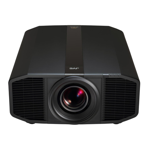
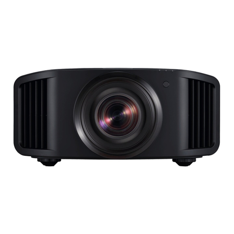
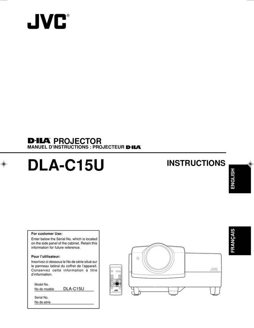
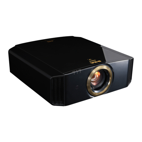
JVC DLA-RS4500K User manual

SERVICE MANUAL
COPYRIGHT © 2017 JVC KENWOOD Corporation No.PA056<Rev.002>
2017/6
D-ILA PROJECTOR
PA056<Rev.002>20176SERVICE MANUAL
DLA-RS4500K, DLA-Z1E, DLA-Z1C,
DLA-VS4500
COPYRIGHT © 2017 JVC KENWOOD Corporation
TABLE OF CONTENTS
1 PRECAUTION. . . . . . . . . . . . . . . . . . . . . . . . . . . . . . . . . . . . . . . . . . . . . . . . . . . . . . . . . . . . . . . . . . . . . . . . . . . 4
2 SPECIFIC SERVICE INSTRUCTIONS . . . . . . . . . . . . . . . . . . . . . . . . . . . . . . . . . . . . . . . . . . . . . . . . . . . . . . . . 8
3 DISASSEMBLY . . . . . . . . . . . . . . . . . . . . . . . . . . . . . . . . . . . . . . . . . . . . . . . . . . . . . . . . . . . . . . . . . . . . . . . . 12
4 ADJUSTMENT . . . . . . . . . . . . . . . . . . . . . . . . . . . . . . . . . . . . . . . . . . . . . . . . . . . . . . . . . . . . . . . . . . . . . . . . . 16
5 TROUBLESHOOTING . . . . . . . . . . . . . . . . . . . . . . . . . . . . . . . . . . . . . . . . . . . . . . . . . . . . . . . . . . . . . . . . . . . 20

2 (No.PA056<Rev.002>)
SPECIFICATION
Item
DLA-RS4500K
DLA-Z1E
DLA-Z1C
DLA-VS4500
GENERAL
TYPE D-ILA PROJECTOR with Laser Light and D-ILA Native 4K device. )
POWER AC100 to 240V 50/60Hz Max750W ( Standby mode: 1.5W, Eco mode* : 0.4W )
* Only DLA-RS4500K, DLA-Z1E, DLA-Z1C
Operating temp./hum. +5 to +35, 20% to 80% (no-condensation)
Strage temp./hum. -10 to +60 (no-condensation)
Installation Height Below 5,000 ft (1,524 m) or less
Installation Angle Free Angle
Dimensions About. 500mm (W) x 235mm (H) x 720mm (D) (The height without a foot is 215 mm)
Box dimensions About. 657mm (W) x 449mm (H) x 860mm (D)
Mass MAX37.5kg / MAX45kg (BOX) with Lens MAX35.5kg / MAX43kg (BOX), Lenz less
Accessories
Remote control (RM-MH24G) x1
Lens Cover x1
Grille x2
Remote control (RM-MH25G) x1
Lens protect cover x1
Grille x2
Quick user guide: 1piece (User guide download from WEB site)
Option
Projector Calibration Software Ver.8 (Free distribu-
tion) (Recommended OS: Windows 7, 8, 10 for each
32, 64 bit version)
Commercial calibration software (Paid distribution):
PK-CS 1601 (recommended OS: Windows 7, 8, 10
for each 32, 64 bit version), color luminometer (Refer
to the instruction manual for supported models)
OPTICAL
D-ILA device
Size: 0.7-inch (R, G, B devices )
Pixels: [ H:4096 pixels x V:2160 pixels ] (3 devices) total Pixels: 8,847,360 pixels,
Aspect: 17 : 9 (1.57mm x 0.83mm)
Laser light source
BLU-Escent Technology (Laser and Phosphor), Power 510W
Average usage time: 20,000h ( At High LD Power ),
30,000h ( At Mid LD Power ), 40,000h ( At Low LD
Power)
Average usage time: 20,000 hours (LD Current Max)
/ 40,000 hours (LD Current Min / Auto Intensity)
Projection lens
With lens / Can not Exchange Without lens / Optional lens installed
Power zoom (2x), power focus, power shift Vertical
±90%, Horizontal ±40% (Operating range of vertical
and horizontal mutually affects one another.)
Size of angle of view and throw distance when the
size of angle of view is 16:9 (3840 x 2160): Approx.
60/1.75m (Wide) - Approx. 280/17.14m (Tele)
-
Option lens Not used GL-MZ4014SZW
Power zoom / Focusing / Shift possible
Bright Typical 3,000lm (At High LD Power) Typical 3,000lm (LD Current MAX)
Contrast ANSI Contrast (Typical 160 : 1)
DYNAMIC (Infinite : 1) -
Color gamut SRGB/DCI full cover *BT.2020, 80% or more sRGB 100%

(No.PA056<Rev.002>) 3
Design and specifications are subject to change without notice.
INPUT CONNECTORS
HDMI
2-System (screw lock mechanism) / Equivalent to
HDMI2.0b
HDCP2.2 / 4K signals / 3D signals (FP, SBS, TAB) /
Deep Color: 8/10/12bit / Color space: YCbCr (4:4:4),
YCbCr (4:2:2), RGB / Input level: 0-255 (PC), 16-235
(Video), 16-255 (Super White)
For details of supported signals, refer to the WEB in-
struction manual.
To view all supported signals of this unit, we recom-
mend cables that support a transfer speed of
18Gbps.
EDID can be switched at the user menu only for the
HDMI 2 terminal.
EDID setting value A: Factory default (HDMI2.0b) /
B:4K input not allowed (DLA-X95R, X75R, X55R,
X35 equivalent)
Not used
Display
Port
terminals Not used
4 lines / Display Port, 1 input mode (Display Port 1 to
4 can be selected)
2 input mode (using Dipaly Port 1 and 3, 2 stripes,
frame sequential)
4 input mode (using Dipaly Port 1 to 4, cross, 4
stripes, frame sequential)
Input level - INPUT MODE: 0-255 (PC) /16-235 (Video)
Color space - YCbCr (4:4:4), YCbCr (4:2:2), RGB
version - Equivalent to Ver.1.2
HDCP version - incompatible
Input (Max) - 4096 x 2160 @ 120Hz
Deep Color - 8/10/12bit
CONTROLL CONNECTORS
Trigger
1 line / Ø3.5 mm DC Power jack ( ) / 12 V /
maximum 0.1 A Not used
Output timing: off / on (Power) / on (Anamo)
IR Remote
IR remote control, Distance: 7m, Angle range: Horizontal ±30 degrees, Vertical ±20 degrees
One remote control sensor each in front and behind the unit
Remote control A/B (Factory default: "A", To switch settings: Choose user menu on the unit, press "MENU"
and "BACK" on the remote control at the same time)
ECO Mode OFF(Factory default value) :DLA-RS4500K
ON (Factory default value) : Except DLA-RS4500K Not used
LAN terminal
1 line / RJ-45 plug
10BASE-T/100BASE-TX
Supports DHCP / Control 4 SDDP (ON / OFF possible)
PJ control / service correspondence / calibration
compatible
1 line / RJ-45 plug
10BASE-T/100BASE-TX
Supports DHCP / PJ control / service correspon-
dence / calibration compatible / for firmware up
RS-232 terminal 1-System/RS-232C/D-Sub9 pin, JVC External command system (HD-ILA compliant), all settings status,
individual retrieval possible, maintains OSD display when reference commands are received during OSD
display, (except SSSV)
Syncro terminal Not used 1 line / Ø3.5 mm stereo mini ( ) / 5V, TTL output
3D SYNCRO terminal 1 line / Mini DIN 3 Pin
Emitter PK-EM 2 (wireless system) / PK-EM 1 (Infra-
red system: Discontinued product)
Not used
SERVICE terminal (USB) 1 line / USB Type A / for firmware up
Wired remote Not used 1 line / Ø3.5 mm stereo mini ( ) / Power sup-
ply 5V, maximum 3mA output / signal 5V, TTL input
Corresponding signal
Refer to the WEB instruction manual.
Item
DLA-RS4500K
DLA-Z1E
DLA-Z1C
DLA-VS4500

4 (No.PA056<Rev.002>)
SECTION 1
PRECAUTION
1.1 SAFETY PRECAUTIONS
Prior to shipment from the factory, JVC products are strictly in-
spected to conform with the recognized product safety and elec-
trical codes of the countries in which they are to be
sold.However,in order to maintain such compliance, it is equally
important to implement the following precautions when a set is
being serviced.
1.1.1 PRECAUTIONS DURING SERVICING
(1) Locations requiring special caution are denoted by labels
and inscriptions on the cabinet, chassis and certain parts of
the product.When performing service, be sure to read and
comply with these and other cautionary notices appearing
in the operation and service manuals.
(2) Parts identified by the symbol and shaded ( ) parts
are critical for safety.
Replace only with specified part numbers.
NOTE :
Parts in this category also include those specified to
comply with X-ray emission standards for products
using cathode ray tubes and those specified for
compliance with various regulations regarding spu-
rious radiation emission.
(3) Fuse replacement caution notice.
Caution for continued protection against fire hazard.
Replace only with same type and rated fuse(s) as speci-
fied.
(4) Use specified internal wiring. Note especially:
• Wires covered with PVC tubing
• Double insulated wires
• High voltage leads
(5) Use specified insulating materials for hazardous live parts.
Note especially:
• Insulation Tape
• PVC tubing
• Spacers
• Insulation sheets for transistors
• Barrier
(6) When replacing AC primary side components (transformers,
power cords, noise blocking capacitors, etc.) wrap ends of
wires securely about the terminals before soldering.
Fig.1-1-1
(7) Observe that wires do not contact heat producing parts
(heatsinks, oxide metal film resistors, fusible resistors, etc.)
(8) Check that replaced wires do not contact sharp edged or
pointed parts.
(9) When a power cord has been replaced, check that 10-15
kg of force in any direction will not loosen it.
Fig.1-1-2
(10) Also check areas surrounding repaired locations.
(11) Products using cathode ray tubes (CRTs)In regard to such
products, the cathode ray tubes themselves, the high volt-
age circuits, and related circuits are specified for compli-
ance with recognized codes pertaining to X-ray emission.
Consequently, when servicing these products, replace the
cathode ray tubes and other parts with only the specified
parts. Under no circumstances attempt to modify these cir-
cuits.Unauthorized modification can increase the high volt-
age value and cause X-ray emission from the cathode ray
tube.
(12) Crimp type wire connectorIn such cases as when replacing
the power transformer in sets where the connections be-
tween the power cord and power trans former primary lead
wires are performed using crimp type connectors, if replac-
ing the connectors is unavoidable, in order to prevent safe-
ty hazards, perform carefully and precisely according to the
following steps.
•Connector part number :E03830-001
•Required tool : Connector crimping tool of the proper
type which will not damage insulated parts.
•Replacement procedure
a) Remove the old connector by cutting the wires at a
point close to the connector.Important : Do not re-
use a connector (discard it).
Fig.1-1-3
b) Strip about 15 mm of the insulation from the ends
of the wires. If the wires are stranded, twist the
strands to avoid frayed conductors.
Fig.1-1-4
c) Align the lengths of the wires to be connected. In-
sert the wires fully into the connector.
Fig.1-1-5
d) As shown in Fig.1-1-6, use the crimping tool to
crimp the metal sleeve at the center position. Be
sure to crimp fully to the complete closure of the
tool.
Fig.1-1-6
e) Check the four points noted in Fig.1-1-7.
Fig.1-1-7
Power cord
cut close to connecto
r
15 mm
Connecto
r
Metal sleeve
1.25
2.0
5.5
Crimping tool
Not easily pulled free Crimped at approx. cente
r
of metal sleeve
Conductors extended
Wire insulation recessed
more than 4 mm

(No.PA056<Rev.002>) 5
1.1.2 SAFETY CHECK AFTER SERVICING
Examine the area surrounding the repaired location for damage
or deterioration. Observe that screws, parts and wires have been
returned to original positions, Afterwards, perform the following
tests and confirm the specified values in order to verify compli-
ance with safety standards.
(1) Insulation resistance test
Confirm the specified insulation resistance or greater be-
tween power cord plug prongs and externally exposed
parts of the set (RF terminals, antenna terminals, video and
audio input and output terminals, microphone jacks, ear-
phone jacks, etc.).See table 1 below.
(2) Dielectric strength test
Confirm specified dielectric strength or greater between
power cord plug prongs and exposed accessible parts of
the set (RF terminals, antenna terminals, video and audio
input and output terminals, microphone jacks, earphone
jacks, etc.). See Fig.1-1-11 below.
(3) Clearance distance
When replacing primary circuit components, confirm spec-
ified clearance distance (d), (d') between soldered termi-
nals, and between terminals and surrounding metallic
parts. See Fig.1-1-11 below.
Fig.1-1-8
(4) Leakage current test
Confirm specified or lower leakage current between earth
ground/power cord plug prongs and externally exposed ac-
cessible parts (RF terminals, antenna terminals, video and
audio input and output terminals, microphone jacks, ear-
phone jacks, etc.).
Measuring Method : (Power ON)Insert load Z between
earth ground/power cord plug prongs and externally ex-
posed accessible parts. Use an AC voltmeter to measure
across both terminals of load Z. See Fig.1-1-9 and follow-
ing Fig.1-1-12.
Fig.1-1-9
(5) Grounding (Class 1 model only)
Confirm specified or lower grounding impedance between
earth pin in AC inlet and externally exposed accessible
parts (Video in, Video out, Audio in, Audio out or Fixing
screw etc.).Measuring Method:
Connect milli ohm meter between earth pin in AC inlet and
exposed accessible parts. See Fig.1-1-10 and grounding
specifications.
Fig.1-1-10
Fig.1-1-11
Fig.1-1-12
NOTE :
These tables are unofficial and for reference only. Be sure to confirm the precise values for your particular country and locality.
Chassis
Power cord
primary wire
d'
d
ab
c
V
A
Externally
exposed
accessible part
Z
Exposed accessible part
Grounding Specifications
AC inlet
Region
USA & Canada
Europe & Australia
Grounding Impedance (Z)
Z 0.1 ohm
Z 0.5 ohm
Earth pin
MIlli ohm meter
AC Line Voltage Region
Japan
Europe & Australia
R 1 M /500 V DC
USA & Canada 1 M R 12 M /500 V DC
R 10 M /500 V DC
Insulation Resistance (R)Dielectric Strength Clearance Distance (d), (d')
100 V
100 to 240 V
110 to 130 V
110 to 130 V
200 to 240 V
AC 1 kV 1 minute
AC 1.5 kV 1 minute
AC 1 kV 1 minute
(Class )
(Class )
AC 3 kV 1 minute
AC 1.5 kV 1 minute
d, d' 3 mm
d, d' 4 mm
d, d' 3.2 mm
d' 8 m m (Power cord)
d' 6 m m (Primary wire)
d 4 m m
AC Line Voltage Region
Japan
Europe & Australia
USA & Canada
Load Z Leakage Current (i) a, b, c
100 V
110 to 130 V
110 to 130 V
220 to 240 V
i 1 mA rms
i 0.5 mA rms
i 0.7 mA peak
i 2 mA dc
i 0.7 mA peak
i 2 mA dc
Exposed accessible parts
Antenna earth terminals
Other terminals
1
1.5
2
50
0.15

6 (No.PA056<Rev.002>)
1.2 WARNING AND CAUTION LABELS
• Labels advising of warning and caution are affixed on and in various locations of the product.
• Take careful notice of these during service and inspection.
1.3 FOR THE CUSTOMERS IN THE U.S.A. AND CANADA
CAUTION
Use of controls or adjustments or
performance of procedures other
than those specified herein may re-
sult in hazardous radiation expo-
sure.
This Projector is classified as a
CLASS 3R LASER PRODUCT.
This CLASS 3R LASER PRODUCT label and Caution label is
located on the Rear Side surface of the projector.
Location information of the labels
APERTURE LABEL
The APERTURE LABEL is located on the top cover.
1.4 FOR THE CUSTOMERS IN OTHER COUNTRIES
CLASS 1 LASER PRODUCT
LASER CAUTION LABEL
WARNING
Do not look into the lens while in use.
CAUTION
Use of controls or adjustments or performance of procedures
other than those specified herein may result in hazardous ra-
diation exposure.
Location information of the labels
IEC62471-5
Location information of the labels
As with any bright light source, do not stare into the beam, RG2
IEC 62471-5:2015
1.5 ADDITIONAL CAUTIONARY ITEMS
• During adjustments and other work with the cover removed,
extreme care is needed to avoid electric shock.
• Use care to avoid touching the fan or safety switch terminals
during work with the cover removed.
Class Label advisory Location
WARNING High voltage caution
Do not open the cabinet unless you are the service person.
The interior consists of many high voltage parts. It is dangerous to touch them.
REAR PANEL
Caution when connecting power plug
"Be sure to perform ground connection."
"Ground connection must be performed before connecting the power plug to a power source. To
remove ground connection, be sure to remove the power plug from the power source first."
CAUTION • Do not insert or allow foreign objects such as metal and combustible objects to enter the in-
ternal parts from air vents.
• Do not block the air vents.
-Do not look into the lens while the projector is in use. TOP CABINET
LASER RADIATION
AVOID DIRECT EYE
EXPOSURE
CLASS 32 LASER PRODUCT
WAVE LENGTH : 453nm
MAX OUTPUT : 83.56mW
RAYONNEMENT LASER
EVITER L’EXPOSITION
DIRECTE DES YEUX
PRODUIT LASER DE CLASSE 3R
LONGUEUR D'ONDE : 453nm
SORTIE MAX : 83.56mW
RADIACION LASER
EVITAR LA EXPOSICION
DIRECTA DE LOS OJOS
CLASE 3R PRODUCTO LASER
LONGGITUD DE ONDA : 453nm
SALIDA MAX : 83.56mW
IEC/EN60825-1 2007
LASER CAUTION LABEL
LASERRADIATION
AVOIDDIRECT EYE
EXPOSURE
CLASS32 LASER PRODUCT
WAVELENGTH : 453nm
MAXOUTPUT : 83.56mW
RAYONNEMENTLASER
EVITERL’EXPOSITION
DIRECTEDES YEUX
PRODUITLASER DE CLASSE 3R
LONGUEURD'ONDE : 453nm
SORTIEMAX : 83.56mW
RADIACION LASER
EVITARLA EXPOSICION
DIRECTADE LOS OJOS
CLASE3R PRODUCTO LASER
LONGGITUDDE ONDA : 453nm
SALIDAMAX : 83.56mW
IEC/EN60825-1 2007
LASER APERTURE
LASER APERTURE
APERTURE LABEL
IEC62471-5 LABEL
LASER CAUTION LABEL

(No.PA056<Rev.002>) 7
• Select a stable, horizontal work site to prevent dropping the
product and components.
• Use the power cord and interface cable supplied with the prod-
uct.
Before starting work, be sure to also check the safety no-
tices contained in the instruction manual.
1.6 INSTALLATIONS
1.6.1 INSTALLATION METHOD
This projector comes with the D-ILA system (reflecting type ac-
tive matrix liquid crystal system) that does not require conver-
gence adjustment.
Note the following when placed on a floor (refer to OPERATING
INSTRUCTIONS for actual operating method).
(1) Place the projector at the position needed for the required
image size, and observe that the projector is not tilted hor-
izontally.
*Refer to the WEB instruction manual for the projection dis-
tance.
Example: For 16:9 and the screen size is 60 inch, the tele-
end will be 1.75m; for 280 inch, the wide end will be
17.14m.
(2) Adjust the placement site and screen tilt so that the projec-
tion angle is perpendicular to the screen. Adjust the place-
ment site and screen position (height) so that the projection
lens center is at the lower edge of the screen.
(3) Project an image on the screen. (Connect video equipment
and power source, switch power on and select the input.)
(4) Slight adjustment will be made to the projection position
and projection angle of the image. When the projection po-
sition (height) shifts downward or when the projection an-
gle is not appropriate (lower end of the image widens) and
adjustment cannot be made to the installation location and
screen, adjust using the 4 movable feet at the bottom.
(5) By using "ZOOM" in LENS CONTROL, adjust for suitable
image size.
(6) By using "FOCUS" in LENS CONTROL, adjust to correct
image blur.
1.6.2 INSTALLATION SITE AND STATUS
The projector contains some fans for cooling. If the air inlets or
the vent holes of cooling fans are blocked, cooling efficiency may
deteriorate and temperature inside this unit will rise, and then it
can lead to abnormal operation and failure. Also observe there
is plenty of free space between the projector and adjacent walls,
ceiling and other equipment. Note that excess heat can cause
failure and damage to both the projector and nearby equipment.
Therefore, please make sure pay attention not to block the air in-
lets or the vent holes of cooling fans and allow sufficient space
around this unit.
1.6.3 DO NOT INSTALL AT THE FOLLOWING.
This unit is a precision device. Please refrain from installing or
using it at the following locations. Otherwise, it may cause fire or
malfunction.
• Dusty, wet and humid places
• Places subject to oily smoke or cigarette smoke
• On top of a carpet or bedding, or other soft surfaces
• Places exposed to direct sunlight
• Places with a high or low temperature
• Do not install this unit in a room that is oily or subject to ciga-
rette smoke. Even a small quantity of smoke or oiliness can
have a long-term impact on this unit.
* This unit produces a great amount of heat, and is designed to
take in cool air to cool its optical components. Using the unit at
the above locations may cause dirt to attach to the light path,
thereby resulting in dark images or dull colors.
* Dirt that sticks to the optical components cannot be removed.
1.6.4 MAINTAIN CLEARANCE FROM THE WALL, ETC.
As the unit discharges a large amount of heat, install it with ade-
quate clearance from the surroundings as shown below.
Leave the front area of the unit unblocked.
If there is any obstructing object in front of the exhaust vent, hot
air will flow back to the unit and cause it to heat up. Hot air flowing
out of the unit may cause shadows on the screen (heat haze phe-
nomenon).
1.7 NOTE ON PACKAGING MATERIALS
CAUTION:
Make sure to collect all the plastic bags used for packing this
product.
Improper use of these plastic bags by the user can lead to haz-
ardous accident.
150 mm and above
300 mm
and above
150 mm
and above
Front
300 mm
and above
200 mm
and above

8 (No.PA056<Rev.002>)
SECTION 2
SPECIFIC SERVICE INSTRUCTIONS
2.1 DIFFERENCE POINT
Differences other than the following items For details, refer to P2, 3 "Specification" and WEB instruction manual.
2.2 SUPPORT THE REPAIR OF EACH PCB/BLOCK
CAUTION
(1) Repair the item on the above replacement parts, do not use any other parts.
(2) Unplug the power supply cord before replacement parts.
(3) Do not stare into lens before replacement.
(4) Please perform the maintenance regularly to keep the product in compliance.
Item
DLA-RS4500K
DLA-Z1C
DLA-Z1E
DLA-VS4500
Model code A0A1 A0B1
Input terminal HDMI x 2 Display Port x 4
lens Yes (no replacement) No (option)
Item
Part No.
Method for repair
DLA-RS4500K
DLA-Z1C
DLA-Z1E
DLA-VS4500
OPTICAL UNIT (including DD PWB) Z1OP-S VS4500OP-S OP UNIT exchange
PROCESSOR PWB XD1-022W-00 XD1-027W-00 PWB exchange
FRONT PWB KD1-025W-001 PWB exchange
LD UNIT B3A-0023-00 B3A-0023-01 LD UNIT exchange
LD DRIVER PWB [POWER UNIT (CC)] (3 pcs) W0H-0004-00 PWB exchange
INTERLOCK PWB FOR TOP PLATE KD1-025W-005 PWB exchange
INTERLOCK PWB FOR FRONT COVER KD1-025W-006 PWB exchange
AC INPUT PWB KD1-026W-001 PWB exchange
POWER PWB [POWER UNIT (CC)] (2 pcs) W0H-0028-01 PWB exchange
MOTOR PWB XD1-024W-00 XD1-024W-01 PWB exchange
DD PWB XD1-023W-00 XD1-023W-01 PWB exchange
KEYPAD PWB KD1-025W-002 PWB exchange
C. SENS PWB KD1-025W-004 PWB exchange
P. SENS PWB (1 pcs): DLA-VS4500
P. SENS PWB (2 pcs): Except DLA-VS4500
KD1-025W-00A PWB exchange
EXTERNAL TEMPERATURE SENSOR PWB KD1-025W-007 PWB exchange
INTERNAL TEMPERATURE SENSOR PWB KD1-025W-008 PWB exchange
RELAY 1 PWB KD1-025W-003 PWB exchange
RELAY 2 PWB KD1-026W-002 PWB exchange
TERMINAL PWB KD1-025W-009 KD1-025W-00B PWB exchange
DD COOLING FAN F0K-0202-00 Part exchange
OP COOLING FAN F0K-0202-00 Part exchange
DEVICE COOLING FAN (3 pcs) F0K-0202-00 Part exchange
INTAKE FAN (2 pcs) F0K-0204-00 Part exchange
EXHAUST FAN (2 pcs) F0K-0204-00 Part exchange
LD COOLING FAN (3 pcs) F0K-0203-00 Part exchange
AIR FILTER F1K-0062-00 Part exchange
SPONGE SPACER J3K-0049-10 Part exchange
REMOTE CTL (IR) A7A-0022-00
(RM-MH24G)
A7A-0022-01
(RM-MH25G)
REMOTE CTL exchange

(No.PA056<Rev.002>) 9
2.3 NOTES ON REPAIRING LASER PRODUCTS
The light leakage of this product (when the shield cover is
assembled correctly) is Class 1 or below. The product is
designed with safety aspects taken into consideration.
However, as an extra precaution during repair, please take note
of the followings:
(1) Avoid lighting up this product unnecessarily while the cab-
inet is removed.
(2) Wear a pair of laser safety goggles to access the inside of
the shield cover. (Light leakage equivalent to Class 4 may
be emitted.)
Open the cover to the minimum required area. Be sure to
close the shield cover after completing the diagnosis and
repair.
(3) If the interlock is released for fault diagnosis and repair, be
sure to restore the interlock and confirm its operation after
completing the diagnosis and repair.
(4) Never remove the covers for the optical unit and the LD
block.
(5) Be sure to turn off the laser light, attach the shield cover
and unplug the power cord when you leave the service lo-
cation.
2.3.1 Laser Safety Goggles
• The laser safety goggles protect the eyes by absorbing the
scattered laser light.
Make sure to check the wavelength of the laser light for appro-
priate use.
• Be sure to use laser safety goggles with wavelength range of
448 to 462 and OD value 5 or above.
• Your eyes will not be protected if the wavelength range of the
goggles is not within the specified range.
• The higher the OD value, the greater the protection level the
laser safety goggles provide. The attenuation of incident light
increases thereby lowering the transmittance.
• Do not look into the light even when using the laser safety gog-
gles. (Light leakage equivalent to Class 4 may emit from the
projection lens and gap between the cover.)
• Do not expose the laser safety goggles to direct laser beam.
Otherwise, it may damage the goggles.
• Do not use laser other than the laser and wavelength specified.
(There may be lasers of the same name with different wave-
lengths)
• Do not remove the laser safety goggles during operations.
• Do not use the laser safety goggles as light shielding goggles
for welding.
• The complete absorption-type products are not protective
equipment that absorbs laser beam completely. (Check the
absorption characteristics of the safety goggles.)
• Do not use products with a standard visible light transmittance
of 20% or less in dark areas.
• Do not use the laser safety goggles once the goggles have
been exposed to high laser energy or if the goggles are dam-
aged.
• The laser safety goggles absorb a great amount of light of spe-
cific wavelengths. This affects the color balance of your eyes
temporarily after a long period of use.
• Usage environment, storage environment (direct sunlight, high
temperature, or high humidity), and scratches may change the
optical density of the goggles. Replace the goggles periodical-
ly.
2.3.2 What is the OD (Optical Density) value?
• The amount of transmitted light is expressed as transmittance %.
• The greater the absorption (transmittance % very close to ze-
ro) of specific wavelengths such as laser light, the safer it is for
your eyes.
• When the transmittance becomes lower, the number of zeros
increases in the decimal fraction making it complicated and
difficult to interpret the value.
• Optical Density (OD) value expresses transmittance in an easy
to understand manner.
• Optical Density is the logarithm of the degree of absorption.
The relationship with transmittance is shown in the following
table.
Model No. : YL 335-AR(45)/Opto Sigma Co.
Recommended laser safety goggles
Optical Density
(OD)
0
1
2
3
4
5
6
0
1/10
1/100
1/1000
1/10000
1/100000
1/1000000
100
10
1
0.1
0.01
0.001
0.0001
Attenuation Transmittance
(%)
Highly safe

10 (No.PA056<Rev.002>)
2.4 FUNCTIONS
2.4.1 LED INDICATIONS
The LED operations are as follows.
NOTE:
When the unit is on standby in "ECO Mode" (LED: STANDBY/
ON lamp is off), press the "STANDBY/ON" button on the re-
mote control to cancel the standby state (LED: STANDBY/ON
lamp lights up in red). Press "STANDBY/ON" button the sec-
ond time to start up. When the unit is on standby in "ECO
Mode", press the unit power button once to start up.
STAND-BY LED
Light on (Red): Standby mode
Light on (Green): While activating the LD
Blinking (Green): "Hide" on
Blinking (Red): Cool Down mode
Blinking (Red/Green): Adjust mode
All Off: During image projection
LIGHT LED
Light on: Duaring Software update or Light source lifetime over
Extinguished: Warning mode
WARNING LED
Light on: Duaring Software update or WARNING mode
Extinguished: Warning mode
Note:
Please refer to the TROUBLESHOOTING section for the de-
tails of warning indications by LED.
2.4.2 OPERATION BUTTON LOCATION
2.4.3 LED LOCATION
2.5 SERVICE MENU
The service menu contains items not ordinarily needed by the us-
er. Use these as necessary during service.
2.5.1 ENTER
(1) No menu shown.
(2) Press the [OK] button.
(3) Within press the [] button.
(4) Within press the [] button.
(5) Within press the [OK] button.
(6) Within press the [BACK] button.
(7) Within press the [OK] button to display the service menu.
NOTE:
When the Service Menu Screen is not displayed, go back to
the beginning. It is recommended that you press the buttons a
little earlier and steadily. (Within about 1 second)
2.5.2 RELEASE
Press the [MENU] button to exit the menu indication.
2.5.3 BASIC OPERATION
(1) Choose the SETTING MENU with the [] or [] button.
(2) When the [] button is pressed after choosing the SET-
TING MENU, the cursor will shift to the SETTING / AD-
JUSTMENT ITEMS of each SETTING MENU.
(3) When the cursor is shifted, choose the SETTING / AD-
JUSTMENT ITEMS with the [] or [] button.
(4) Using the [] or [] button, change the setup values and
adjustment values, respectively.
(5) When the [EXIT] button is pressed, the cursor will return to
the SETTING MENU.
(6) When the [BACK] button is pressed, the SERVICE MENU
will go out of the screen.
REAR VIEW
To turn on/off
the power
To switch input / Up key
To switch input / Down key
Left key
To display the
menu To return to the
previous menu
Right key
FRONT VIEW
STANDBY/ON
LIGHT
WARNING
STANDBY/ON LIGHT WARNING

(No.PA056<Rev.002>) 11
2.5.4 Service Menu Screen
2.5.5 SETTING ITEMS
*1: Exclusive for DLA-RS4500K, DLA-Z1E and DLA-Z1C. DLA-VS4500 is not displayed.
Soft version screen
Main menu Screen
Service
Soft Ver.
Pixel Shift
Adjust Pattern
Lens Position Reset *1
3D L/R Picture *1
All Reset
>
>
>
>
Standard
>
> Soft Ver.
Model / Location
Soft Ver.
Main
VP
DDM
DDS
Mecha
HDMI_DRV
CMS_DATA
MEMC
LD_DRV
A0XX / XXX
vX.XX
vXX.X
XXXXXX / XXXXXX
XXXXXX / XXXXXX
XXXXXX
XXXXXX
XXXXXXXX *1
XXXXXX
XXXX / XXXX *1
XXXX / XXXX / XXXX
Pixel shift screen
> Pixel Shift
Horiz. Red
Horiz. Bule
Vert. Red
Vert. Bule
0
0
0
0
Adjustment pattern screen *Display in the following order.
1. Color Cross Hatch
2. Cross Hatch(Green)
3. Focus / Zoom / Shift
4. Cross Hatch(pixel adjust)
5. Color Bar
6. ANSI Cntrast
7. Optical meas 100%
8. Optical meas 50%
9. Optical meas 10%
10. Dark level
11. Bright level
12. Color palette
13. Ramp(White)
14. Ramp(Red)
15. Ramp(Green)
16. Ramp(Blue)
17. Raster(White 100%)
18. Raster(Gray 50%)
19. Raster(Gray 0%)
20. Raster(Red)
21. Raster(Green)
22. Raster(Blue)
23. Raster(Cyan 100%)
24. Raster(Megenta 100%)
25. Raster(Yellow 100%)
Item Selection (variable) range Factory setting Function
Soft Ver.
Model / Location Display only - Model code is displayed.
Soft Ver. Display only - Software summary version (displayed on the user
menu) are displayed.
Main Display only - Main CPU version is displayed.
VP Display only - Versions for VP_FPGA / VP_CPU are displayed.
DDM Display only - Versions for DD1 (Master)_FPGA / DD1 (Mas-
ter)_CPU are displayed.
DDS Display only - DD2 (Slave) FPGA version is displayed.
Mecha Display only - Mecha CPU version is displayed.
HDMI_DRV *1 Display only - HDMI Driver IC version is displayed.
CMS_DATA Display only - Color management data version is displayed.
MEMC *1 Display only - MEMC version is displayed.
LD_DRV Display only - Versions for LD driver 1 / LD driver 2 / LD driver 3 are
displayed.
Pixel shift
Horizontal R -2 to 2 0 Horizontal R pixel shift adjustment
Horizontal B -2 to 2 0 Horizontal B pixel shift adjustment
Vertical R -2 to 2 0 Vertical R pixel shift adjustment
Vertical B -2 to 2 0 Vertical B pixel shift adjustment
Adjustment pattern - Color cross hatch Adjustment pattern display
Lens Position Reset *1 -
3D L/R Picture *1 Standard / L/R Switch Standard Phase setting of 3D signal
All reset - - Restore main unit setting to factory default

12 (No.PA056<Rev.002>)
SECTION 3
DISASSEMBLY
3.1 CAUTION AT DISASSEMBLY
• Make sure that the power cord is disconnected from the outlet.
• Pay special attention not to break or damage the parts. Also, please pay attention to lens dirt and fingerprints.
• Make sure that there is no bent or stain on the connectors before inserting, and firmly insert the connectors.
• Be sure to reattach the wire clamps removed during the procedure to the original positions. (Attaching the wire clamps in wrong
positions may affect the performance.)
REFERENCE:
When removing each board, remove the connector if necessary. The operation is easier if you write down the connection points (con-
nector numbers) of the connector. For connection of each board, refer to the "WIRING DIAGRAM" of the Standard Circuit Diagram.
3.2 DISASSEMBLY PROCEDURE
3.2.1 REMOVING THE FRONT PWB (Fig.3-1 and Fig.3-2)
(1) Remove the 6 screws, and remove the SIDE COVER.
Fig.3-1
(2) Remove the 2 screws (a), and remove the FRONT COVER.
(3) Remove the 6 screws (b), and remove the CENTER FRAME.
(4) Remove 1 screw (c), and remove the FRONT FRAME.
(5) Remove 4 screws (d), and remove PANEL ASS'Y.
(6) Remove 2 screws (e), and remove the FRONT PWB.
Fig.3-2
3.2.2 REMOVING THE KEY PAD PWB (Fig.3-3)
(1) Remove the 4 screws (a), and remove the FILTER COV-
ER.
(2) Remove the 4 screws (b), and remove the REAR PANEL
ASS'Y.
(3) Remove the 2 screws (c), and remove the KEYPAD PWB.
Fig.3-3
SIDE COVER
SIDE COVER
d
d
a
a
c
b
b
bb
bb
FRONT FRAME
FRONT PWB
CENTER FRAME
d
d
FRONT COVER
PANEL ASS'Y
ee
FILTER COVER
SPONGE FILTER
REAR PANEL ASS'Y KEYPAD PWB
b
b
a
a
a
a
b
b
c
c
AIR FILTER

(No.PA056<Rev.002>) 13
3.2.3 Remove the INTERLOCK PWB, PROCESSOR PWB,
MOTOR PWB and DD PWB (Fig.3-4)
(1) Remove 14 screws (a), and remove the TOP PLATE.
(2) Remove the 2 screws (b), and remove the INTERLOCK
PWB (for the TOP PLATE).
(3) Remove the 4 screws (c), and remove the PROCESSOR
PWB.
(4) Remove the 6 screws (d), and remove the MOTOR PWB.
(5) Remove the 3 screws (e), and remove the DD COOLING
FAN ASSY.
(6) Remove 6 screws (f), and remove the DD SHIELD.
(7) Remove 6 screws (g), and remove the DD PWB.
Fig.3-4
3.2.4 Remove the TERMINAL PWB, LD FAN (Fig.3-5)
(1) Remove 6 screws (a, b, c), and remove the REAR BASE.
(2) Remove the 2 screws (d), and remove the TERMINAL
PWB.
(3) Remove 6 screws (e), and remove the LD FAN.
Fig.3-5
3.2.5 Remove the RELAY 1 PWB, TEMPERATURE SENSOR
PWB and LD UNIT (Fig.3-6)
(1) Remove the 2 screws (a), and remove the BRACKET.
(2) Remove the 3 screws (b), and remove the RELAY 1 PWB.
(3) Remove the 2 screws (c), and remove the BRACKET.
(4) Remove 1 screw (d), and remove the INTERNAL TEM-
PERATURE SENSOR PWB.
(5) Remove the 2 screws (e), and remove the BRACKET.
(6) Remove the 2 screws (f), and remove the FAN BRACKET.
(7) Remove 1 screw (g), and remove the EXTERNAL TEM-
PERATURE SENSOR PWB.
(8) Remove 4 screws (h) and remove the LD UNIT.
Fig.3-6
PROCESSOR PWB
COVER
MOTOR PWB
DD SHIELD
DD PWB
INTERLOCK PWB
(for the TOP PLATE)
TOP PLATE
a
c
c
d
d
d
d
d
d
c
bb
a
aa
a
a
a
a
a
a
a
a
a
a
c
g
g
g
g
g
g
e
f
f
f
f
f
f
e
e
DD COOLING FAN
DD COOLING FAN ASSY
BRACKET
a
c
d
d
c
e
e
e
e
e
e
a
b
b
LD FAN1,2,3 (From the left)
REAR BASE
TERMINAL PWB
RELAY 1 PWB
BRACKET
INTERNAL TEMPERATURE
SENSOR PWB
BRACKET
BRACKET
d
b
a
a
b
b
h
g
c
c
h
h
h
LD UNIT
f
e
e
f
FAN BRACKET
EXTERNAL TEMPERATURE
SENSOR PWB

14 (No.PA056<Rev.002>)
3.2.6 Remove the AC INPUT PWB and POWER PWB (Fig.3-7)
(1) Remove 13 screws (a), and remove the SIDE PLATE.
(2) Remove the 4 screws (b), and remove the AC INPUT PWB.
(3) Remove the 2 screws (c), and remove the INTAKE FAN
and the EXHAUST FAN.
(4) Remove the 2 screws (d), and remove the SHIELDING
COVER.
(5) Remove the 4 screws (e), and remove the BRACKET.
(6) Remove the 12 screws (f), and remove the POWER PWB.
Fig.3-7
3.2.7 Remove the RELAY 2 PWB and LD DRIVER PWB
(Fig.3-8)
(1) Remove 13 screws (a), and remove the SIDE PLATE.
(2) Remove the 4 screws (b), and remove the RELAY 2 PWB.
(3) Remove the 2 screws (c), and remove the INTAKE FAN
and the EXHAUST FAN.
(4) Remove the 2 screws (d), and remove the SHIELDING
COVER.
(5) Remove the 6 screws (e), and remove the BRACKET.
(6) Remove the 12 screws (f), and remove the LD DRIVER
PWB.
Fig.3-8
SIDE PLATE
POWER PWB
POWER PWB
INTAKE FAN
AC INPUT PWB
EXHAUST FAN
SHIELDING COVER
aa
a
a
a
aa
b
c
c
d
f
f
f
f
ff
f
f
e
e
e
e
d
b
aa
aaa
a
b
f
f
f
b
BRACKET
BRACKET
LD DRIVER PWB
SHIELDING COVER
LD DRIVER PWB
LD DRIVER PWB
BRACKET
a
aa
b
b
b
c
c
d
d
f
ff
e
e
e
e
e
e
ff
f
ff
f
b
a
aa
a
a
a
a
aa
a
INTAKE FAN
EXHAUST FAN
SIDE PLATE
RELAY 2 PWB
f
f
f
BRACKET
BRACKET

(No.PA056<Rev.002>) 15
3.2.8 Remove the INTERLOCK PWB and OPTICAL UNIT
(Fig.3-9 and Fig.3-10)
(1) Remove the 8 screws (a), and remove the BRACKET.
(2) Remove the 2 screws (b), and remove the COVER.
(3) Remove the DEVICE COOLING FAN.
(4) Remove 3 screws (c), and remove the DUCT-1.
(5) Remove the DEVICE COOLING FAN.
(6) Remove 3 screws (d), and the REMOVE DUCT-2.
(7) Remove the OP COOLING FAN.
Fig.3-9
(8) Remove the 2 screws (a), and remove the FRONT PLATE.
(9) Remove the 2 screws (b), and remove the INTERLOCK
PWB (for the FONT COVER).
(10) Remove 4 screws (c), and remove the OP BASE.
(11) Remove the 4 screws (d), and remove the OPTICAL UNIT.
Fig.3-10
BRACKET
COVER
DUCT-1
R DEVICE COOLING FAN
OP COOLING FAN
a
a
aa
aa
a
a
b
c
c
d
d
d
c
b
DUCT-2
B DEVICE COOLING FAN
G DEVICE COOLING FAN
FRONT PLATE
OPTICAL UNIT
OP BASE
a
a
b
b
d
d
d
d
c
c
cc
INTERLOCK PWB
(for the FONT COVER)

16 (No.PA056<Rev.002>)
SECTION 4
ADJUSTMENT
4.1 BEFORE STARTING ADJUSTMENT
(1) Adjustment items utilize a personal computer. Be sure to
use the latest adjustment software.
(2) Data back up is required before adjustments.
(3) Allow the equipment and test instruments adequate time
(at least 10 minutes) to warm-up.
(4) Confirm the set is properly connected to the specified AC
power source.
(5) Use care not to disturb internal controls and parts not spe-
cifically mentioned.
(6) Unless specifically mentioned in the "ADJUSTMENT"
steps, do not change any data.
4.2 INSTRUMENTS AND TOOLS
• Oscilloscope
• Adjustment software
• RS-232C Reverse (Cross) cable
• USB cable
• LAN cable
• PC (WINDOWS machine, with NET Framework 4.0 installed)
4.3 REQUIRED ADJUSTMENTS BY REPLACING COMPONENTS
The following adjustment procedure is required after replacing PWB ASS'Ys and OPTICAL BLOCK.
4.3.1 COMPONENT REQUIRED ADJUSTMENT AT REPLACING
*1: When the main EEPROM can not be backup.
OS Windows8, 7, XP
Memory More than 16 Mbytes
Hard disk free space More than 5 Mbytes
RS-232C interface At least 1 port
Display resolution Minimum: 800 600 pixels
Recommended: 1024 768 pixels or
more
Display colors Minimum: 8 bits/pixel
Recommended: 16 bits/pixel or more
Input devices Keyboard and mouse
Adjustment items PROCESSOR PWB OPTICAL UNIT DD PWB MOTOR PWB
Main EEPROM backup
Model code writing
Destination writing
Transferring CMS Data from DD PWB
Adjustment data backup of DD PWB
Pixel shift adjustment
Lenz position reset
MAC address writing *1
Setting of mechanical EEPROM initial value
Mecha EEPROM (lens set value etc.) backup

(No.PA056<Rev.002>) 17
4.4 ADJUSTMENT PROCEDURE
Fig.4-1 "Service Commander Software" screen
Fig.4-2 "EEPROM" menu screen
4.4.1 Main EEPROM backup
Note:
Perform this operation during standby mode.
PROCEDURE
(1) Run ServiceCommander Software.
(2) Select Com Port, then connect the PC to the projector
and click "Connect".
(3) Select the EEPROM menu.
(4) Before replacing the PROCESSOR PWB, Click [Read
from ROM] of Main CPUand save file (.mrd) to PC.
(5) After replacing the PROCESSOR PWB, click [Write to
ROM] of Main CPU and select the saved file (.mrd) to
write the backup data.
4.4.2 Model code writing
Note:
Perform this operation during standby mode.
PROCEDURE
(1) Run ServiceCommander Software.
(2) Select Com Port, then connect the PC to the projector
and click "Connect".
(3) Select the info menu.
(4) Select the model code from the Model, and write the
model code.
A0A1-----DLA-RS4500K, DLA-Z1C/E
A0C1-----(Not use)
A0B1-----DLA-VS4500
4.4.3 Destination writing
Note:
Perform this operation during standby mode.
PROCEDURE
(1) Run ServiceCommander Software.
(2) Select Com Port, then connect the PC to the projector
and click "Connect".
(3) Select the info menu.
(4) Select the destination from the Location, and write the
destination.
Instruments ServiceCommander
Software
REPLACING
COMPONENTS
PROCESSOR PWB
Test point
Adjustment menu
Preparation
Instruments ServiceCommander
Software
REPLACING
COMPONENTS
PROCESSOR PWB
Test point
Adjustment menu
Preparation
Instruments ServiceCommander
Software
REPLACING
COMPONENTS
PROCESSOR PWB
Test point
Adjustment menu
Preparation

18 (No.PA056<Rev.002>)
4.4.4 Transferring CMS Data from DD PWB
Note:
• Perform the operation with the power ON.
• Input the signal from external equipment.
PROCEDURE
(1) Run the VP Writer application program.
(2) Select the COM Port.
(3) Click "Write".
(4) CMS data is transferred from the DD PWB.
< If OK >
< If NG >
4.4.5 Adjustment data backup of DD PWB
Note:
• Perform the operation with the power ON.
• Input the signal from external equipment.
BACKUP PROCEDURE
(1) Run ServiceCommander Software.
(2) Select Com Port, then connect the PC to the projector
and click "Connect".
(3) Select the EEPROM menu.
(4) Click [DD Adjust Mode] of DD set ON.
(5) Click A0 of [Read From ROM] and save the anf0 file to
the PC.
(6) In the similar procedure for save the A2,A4,A6 memory.
(7) Click [DD Adjust Mode] of DD set OFF.
PROCEDURE
(1) Run ServiceCommander Software.
(2) Select Com Port, then connect the PC to the projector
and click "Connect".
(3) Select the EEPROM menu.
(4) Click [DD Adjust Mode] of DD set ON.
(5) Click A0 of [Write to ROM] of DD and load of backup the
anf0 file to the PC.
(6) In the similar procedure for the A2,A4,A6 memory.
(7) Click [DD Adjust Mode] of DD set OFF.
4.4.6 Pixel shift adjustment
PROCEDURE
(1) Input color cross-hatch signal.
(2) From the Service menu, set < Adjust > to < Pixel Shift >.
(3) Adjust [H Pixel Adj.R], [H Pixel Adj.B] to make H direction
(Pixel Shift) to become the best point.
(4) Adjust [V Pixel Adj.R], [V Pixel Adj.G] to make V direction
(Pixel Shift) to bectom best point.
4.4.7 Lenz position reset
PROCEDURE
(1) Set lens shift position to mechanical center.
(2) Execute to Lens Position Reset.
Instruments VPWriter REPLACING
COMPONENTS
PROCESSOR PWB
OP UNIT
Test point
Adjustment menu
Preparation
Instruments ServiceCommander
Software
REPLACING
COMPONENTS
DD PWB
Test point
Adjustment menu
Preparation
Instruments REPLACING
COMPONENTS
OP UNIT
Test point
Adjustment menu Service menu
“Adjust” “Pixel shift”
Preparation
Instruments REPLACING
COMPONENTS
OP UNIT
Test point
Adjustment menu Service menu
“Option” “Lens Posi-
tion Reset ”
Preparation

(No.PA056<Rev.002>) 19
4.4.8 MAC address writing
Note:
Perform this operation during standby mode.
PROCEDURE
(1) Run ServiceCommander Software.
(2) Select Com Port, then connect the PC to the projector
and click "Connect".
(3) Select the info menu.
(4) Set the MAC address and click "Write" button.
(5) Confirm the “OK” display.
MAC ADDRESS display position
MAC address is listed in the label of PROCESSOR PWB.
Please fill in the MAC address in the PROCESSOR PWB after
the exchange.
4.4.9 Setting of mechanical EEPROM initial value
Note:
• Perform the operation with the power ON.
• Input the signal from external equipment.
PROCEDURE
(1) Confirm the optical unit lens position is aligned with the
center.
(2) Run ServiceCommander Software.
(3) Select Com Port, then connect the PC to the projector
and click "Connect".
(4) Select the EEPROM menu.
(5) Click [Write to Mecha ROM] of Mecha CPU (4K) and se-
lect the saved initial value file to write the backup data.
4.4.10 Mecha EEPROM (lens set value etc.) backup
Note:
• Perform the operation with the power ON.
• Input the signal from external equipment.
PROCEDURE
(1) Run ServiceCommander Software.
(2) Select Com Port, then connect the PC to the projector
and click "Connect".
(3) Select the EEPROM menu.
(4) Before replacing the MOTOR PWB, Click [Read from
Mecha ROM] of Mecha CPU (4K) and save file to PC.
(5) After replacing the MOTOR PWB, click [Write to ROM] of
Mecha CPU (4K) and select the saved file to write the
backup data.
Instruments ServiceCommander
Software
REPLACING
COMPONENTS
PROCESSOR PWB
Test point
Adjustment menu
Preparation
Instruments ServiceCommander
Software
REPLACING
COMPONENTS
OP UNIT
Test point
Adjustment menu
Preparation
MAC address
Instruments ServiceCommander
Software
REPLACING
COMPONENTS
MOTOR PWB
Test point
Adjustment menu
Preparation

20 (No.PA056<Rev.002>)
SECTION 5
TROUBLESHOOTING
5.1 PROTECTIVE SENSOR AND PROTECTIVE SWITCH
In event of abnormal operation due to circuit or component failure, setting error or other reason, in order to prevent serious damageto
the set and preserve the integrity of peripheral equipment, sensors and switches are provided for protective functions. Cooling iscon-
ducted at the same time a corresponding LED flashes (about 10 seconds). The LED indication with respect to the protective function
is described below.
5.1.1 Protective sensor
5.1.2 Protective switch
5.2 LED (INDICATOR) WARNING INDICATIONS
5.2.1 Led indication contents
If an abnormality occurs during operation (projection), the content of the problem can be determined from flashing LED indica-
tors.When an LED indicates, operation (projection) automatically stops and the cool-down mode (about 10 seconds) is entered then
thestand-by mode.
O: Turned on during operation, : Blinking on during operation, Blinking time: Each time of turning on / off
Type Monitor objective Operating point
Temperature sensor External temperature sensor 45C (LD mode [MID] / [HIGH] is 62C)
Internal temperature sensor 60C
LD block inside (LD 1) 75C
LD block inside (LD 2) 75C
Near DDS IC 100C
Near the DDM IC 100C
Near VP_FPGA 100C
Heat sink of R device 75C
Heat sink of B device 75C
Heat sink of G device 75C
Type Monitor objective State
Interlock switch 1 TOP PLATE Open / close
Interlock switch 2 FRONT COVER Open / close
No Content Blinking LED Blinking time Delay time Number of
blinks
WARNING LIGHT STANDBY/ON
1 LD driver error O - 0.25 s 0.5 s 1
2 Color sensor error O - 0.25 s 0.5 s 3
3 interlock O - 0.25 s 0.5 s 4
4 Firmware update error - 0.25 s 0.5 s 1
5 Fan lock - 0.25 s 0.5 s 2
6 Internal temperature abnormality - 0.25 s 0.5 s 3
7 External temperature abnormality - 0.25 s 0.5 s 4
8 DD PWB error - 0.25 s 0.5 s 1
9 MOTOR PWB error - 0.25 s 0.5 s 2
10 PROCESSOR PWB error - 0.25 s 0.5 s 3
11 POWER PWB error - 0.25 s 0.5 s 4
12 Light source lifetime over - O -
13 On standby - - O (Red)
14 Cooling - - (Red) 0.5 s
15 During Power Up - - O (Red)
16 Power on (Hide off) - - -
17 Power on (HYD) - - (Green) 0.5 s
This manual suits for next models
3
Table of contents
Other JVC Projector manuals

JVC
JVC BLUEscent DLA-VS47NV User manual

JVC
JVC DLA-G150 User manual

JVC
JVC DLA-RS1 User manual

JVC
JVC D-ILA DLA-RS45 User manual

JVC
JVC DLA-HD550 User manual

JVC
JVC DLA-VS2100U User manual

JVC
JVC D-ILA DLA-RS50 User manual

JVC
JVC DLA-SX21E User manual

JVC
JVC DLA-HD550 User manual

JVC
JVC DLA-VS2200ZG User manual

JVC
JVC LX-UH1 User manual

JVC
JVC DLA-F110 User manual

JVC
JVC DLA-NZ9 User manual

JVC
JVC DLA-NX5 User manual

JVC
JVC DLA-SH4KNL User manual

JVC
JVC DLA-X500RBE User manual

JVC
JVC LX-NZ30 User manual

JVC
JVC DLA-X5000 User manual

JVC
JVC Procision DLA-HD950 User manual

JVC
JVC DLA-HX2U - High Definition D-ila Projector User manual