manuals.online logo
Brands
  1. Home
  2. •
  3. Brands
  4. •
  5. JVC
  6. •
  7. Projector
  8. •
  9. JVC DLA-RS45U Installation manual

JVC DLA-RS45U Installation manual

This manual suits for next models

13

Other JVC Projector manuals

JVC DLA-SX21E User manual

JVC

JVC DLA-SX21E User manual

JVC BLU Escent DLA-VS3000G User manual

JVC

JVC BLU Escent DLA-VS3000G User manual

JVC DLA-VS4500 User manual

JVC

JVC DLA-VS4500 User manual

JVC D-ILA DLA-RS65 Use and care manual

JVC

JVC D-ILA DLA-RS65 Use and care manual

JVC DLA-X95R User guide

JVC

JVC DLA-X95R User guide

JVC DLA-SX21U User manual

JVC

JVC DLA-SX21U User manual

JVC DLA-SH4K User manual

JVC

JVC DLA-SH4K User manual

JVC DLA-M20U - D-ila Projector--1.5:1 Fixed User manual

JVC

JVC DLA-M20U - D-ila Projector--1.5:1 Fixed User manual

JVC DLA-SH4KNL User manual

JVC

JVC DLA-SH4KNL User manual

JVC D-ILA DLA-HX1 User manual

JVC

JVC D-ILA DLA-HX1 User manual

JVC DLA-RS15U - Reference Series Home Cinema... Installation guide

JVC

JVC DLA-RS15U - Reference Series Home Cinema... Installation guide

JVC LX-P1010ZE User manual

JVC

JVC LX-P1010ZE User manual

JVC DLA-HD2K User manual

JVC

JVC DLA-HD2K User manual

JVC DLA-G150CLU User manual

JVC

JVC DLA-G150CLU User manual

JVC DLA-X900RKT Owner's manual

JVC

JVC DLA-X900RKT Owner's manual

JVC DLA-RS48U User manual

JVC

JVC DLA-RS48U User manual

JVC D-ILA DLA-RS50 User manual

JVC

JVC D-ILA DLA-RS50 User manual

JVC BHL5006-S User manual

JVC

JVC BHL5006-S User manual

JVC LX-D1010 User manual

JVC

JVC LX-D1010 User manual

JVC DLA-M15U User manual

JVC

JVC DLA-M15U User manual

JVC D-ILA DLA-RS40 User manual

JVC

JVC D-ILA DLA-RS40 User manual

JVC LX-NZ30WE User manual

JVC

JVC LX-NZ30WE User manual

JVC DLA-F110 User manual

JVC

JVC DLA-F110 User manual

JVC D-ILA DLA-RS45 Quick start guide

JVC

JVC D-ILA DLA-RS45 Quick start guide

Popular Projector manuals by other brands

Eiki LC-X985 Specification sheet

Eiki

Eiki LC-X985 Specification sheet

InFocus LitePro 610 quick start

InFocus

InFocus LitePro 610 quick start

Epson EH-TW5900 datasheet

Epson

Epson EH-TW5900 datasheet

FOREVER MLP-100 manual

FOREVER

FOREVER MLP-100 manual

Toshiba TDP-MT8U Specifications

Toshiba

Toshiba TDP-MT8U Specifications

Mitsubishi XD500U specification

Mitsubishi

Mitsubishi XD500U specification

Kodak Ektapro 3020 Illustrated parts list

Kodak

Kodak Ektapro 3020 Illustrated parts list

Toshiba TDP-EW25U Specifications

Toshiba

Toshiba TDP-EW25U Specifications

Barco iQ PRO G500 supplementary guide

Barco

Barco iQ PRO G500 supplementary guide

NEC Showcase Series HT1100 user manual

NEC

NEC Showcase Series HT1100 user manual

Philips LC1341 user guide

Philips

Philips LC1341 user guide

Epson PowerLite 1266 user guide

Epson

Epson PowerLite 1266 user guide

MAGINON DLP 1400S user manual

MAGINON

MAGINON DLP 1400S user manual

Toshiba TLP-380 owner's manual

Toshiba

Toshiba TLP-380 owner's manual

Philips PicoPix PPX2480/EU user manual

Philips

Philips PicoPix PPX2480/EU user manual

Hitachi CP-X605 Series Specifications

Hitachi

Hitachi CP-X605 Series Specifications

Optoma TW1692 user manual

Optoma

Optoma TW1692 user manual

Kodak EKTAPRO instruction manual

Kodak

Kodak EKTAPRO instruction manual

manuals.online logo
manuals.online logoBrands
  • About & Mission
  • Contact us
  • Privacy Policy
  • Terms and Conditions

Copyright 2025 Manuals.Online. All Rights Reserved.

D-ILA
®
Projector
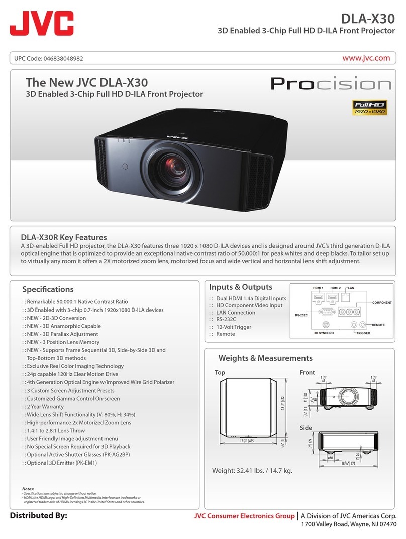
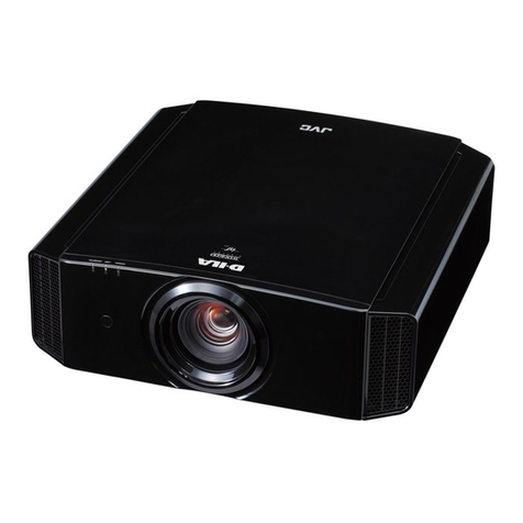
DLA-X30/XC388/RS45 Series
DLA-RS4800 Series
DLA-X70R/XC788R/RS55 Series
DLA-X90R/XC988R/RS65 Series
Cedia Co and
Co unication Specification
Ver. 1.7
2011/12/19
JVCKENWOOD Corp.
Projector Division
(*)D-ILA is the trademark of JVC ENWOOD Corp.
Document No. PJ03220107B
2 80 PJ03220107B
3 80 PJ03220107B
Contents
4 80 PJ03220107B
CONTENTS
1 OUTLINE....................................................7
2 INTERFACE ...............................................7
2.1
Terminal........................................................... 7
2.2
External Controller Connector......................... 7
2.3
Communication Line ....................................... 7
3 PROTOCOL ...............................................8
3.1
Communication specification .......................... 8
3.2
Data format...................................................... 8
3.3
Header table.................................................... 8
3.4
Unit ID table..................................................... 9
3.5
Command table............................................... 9
3.6
Parameter ..................................................... 10
3.6.1
Numeric value parameters.............................10
3.6.2
Special parameter..........................................10
3.7
Exit code ....................................................... 11
3.8
Error handling................................................ 11
3.9
Communication sequence............................. 12
4 COMMAND CONTROL............................13
4.1
NULL command ............................................ 13
4.1.1
Operation.......................................................13
4.1.2
Reference ......................................................13
4.2
Power [PoWer] .............................................. 14
4.2.1
Operation.......................................................14
4.2.2
Reference ......................................................15
4.3
Input [InPut] ................................................... 16
4.3.1
Operation.......................................................17
4.3.2
Reference ......................................................18
4.4
Remote control pass-through [RemoteCode]19
4.4.1
Operation.......................................................20
4.5
Setup [SetUp]................................................ 21
4.5.1
Operation.......................................................22
4.6
Gamma table [GammaTable] ........................ 23
4.6.1
Operation.......................................................24
4.6.2
Reference ......................................................24
4.7
Gamma Bank switch [Gamma-bankSwitch].. 25
4.7.1
Operation.......................................................26
4.7.2
Reference ......................................................26
4.8
Gamma coefficient of Gamma
table ”Custom1 2 3” [GammaPower] ...................... 27
4.8.1
Operation ...................................................... 28
4.8.2
Reference...................................................... 28
4.9
Gamma data of Gamma table “Custom 1 2 3”
[GammaRed, Green, Blue] ..................................... 29
4.9.1
Operation ...................................................... 30
4.9.2
Reference...................................................... 30
4.10 Pannel Alignment (zone) data [Panel
Alignment(Zone) Red, Blue] ………………………. 31
4.10.1
Operation …...………………………………… 32
4.10.2
Reference...................................................... 32
4.11
Source Asking [SourCe].. .......................... 33
4.11.1
Reference...................................................... 33
4.12
Model status asking [MoDel] ..................... 34
4.12.1
Reference...................................................... 35
4.13
Picture adjustment [Adjustment of Picture] 36
4.13.1
Operation ...................................................... 57
4.13.2
Reference...................................................... 61
4.14
LAN setup [Lan Setup] .............................. 65
4.14.1
Operation ...................................................... 66
4.14.2
Reference...................................................... 67
4.15
Service setup [Service Setup] ................... 69
4.15.1
Operation ...................................................... 74
4.15.2
Reference...................................................... 77
5 ADDITIONAL INFORMATION FOR ISF
ADJUSTMENT …………………………….. 79
5.1 State Transitoin Diagram ……………………. 79
5.2 Remote Controll Code ……………………. 79
6 ADDITIONAL INFORMATION FOR THX
ADJUSTMENT …………………………….. 80
5.1 State Transitoin Diagram ……………………. 80
5.2 Remote Controll Code ……………………. 80
Table Number
Table 4-1 NULL CMD................................................ 13
Table 4-2 POWER CMD ........................................... 14
Table 4-3 POWER CMD DATA0............................... 14
Table 4-4 POWER CMD STATUS ............................ 15
Table 4-5 INPUT CMD.............................................. 16
Table 4-6 INPUT CMD DATA ................................... 16
Contents
5 80 PJ03220107B
Table 4-7 REMO CMD ..............................................19
Table 4-8 REMO CMD DATA0-4...............................19
Table 4-9 SETUP CMD ............................................. 21
Table 4-10 SETUP CMD SUB...................................21
Table 4-11 GAMMA TABLE CMD ............................. 23
Table 4-12 GAMMA TABLE CMD DATA...................23
Table 4-13 GAMMA BANK SWITCH CMD................ 25
Table 4-14 GAMMA BANK SWITCH CMD DATA .....25
Table 4-15 GAMMA POWER CMD ...........................27
Table 4-16 GAMMA POWER CMD DATA................. 27
Table 4-17 GAMMA DATA CMD ...............................29
Table 4-18 PANEL ALIGNMENT(ZONE) DATA CMD
..............................................................................31
Table 4-19 SOURCE CMD........................................33
Table 4-20 SOURCE CMD DATA ............................. 33
Table 4-21 MODEL STATUS CMD ........................... 34
Table 4-22 MODEL STATUS CMD DATA
(X30 XC388 RS45) ...............................................34
Table 4-23 MODEL STATUS CMD DATA (RS4800).34
Table 4-24 MODEL STATUS CMD DATA
(X70 XC788 RS55, X90 XC988 RS65) .................34
Table 4-25 ADJUSTMENT CMD ...............................36
Table 4-26 ADJUSTMENT CMD SUB.......................36
Table 4-27 isf ADJUSTMENT CMD DATA ................41
Table 4-28 THX ADJUSTMENT CMD DATA ............42
Table 4-31 COLOR TEMP. TABLE CMD DATA …...43
Table 4-32 COLOR TEMP. CORRECTION CMD
DATA ..................................................................43
Table 4-33 GAMMA CMD DATA ...............................44
Table 4-34 GAMMA CORRECION CMD DATA ........44
Table 4-35 BNRCMD DATA ......................................44
Table 4-36 COLOR MANAGEMENT CMD DATA .....44
Table 4-37 CMS DISPLAY COLOR CMD DATA .......45
Table 4-38 CLEAR MOTION DRIVE CMD DATA ..... 45
Table 4-39 CMD DEMO CMD DATA.........................45
Table 4-40 LAMP POWER CMD DATA ....................45
Table 4-41 COLOR SPACE CMD DATA...................45
Table 4-42 HDMI INPUT LEVEL CMD DATA............45
Table 4-43 HDMI LEVEL CHK CMD DATA...............46
Table 4-44 HDMI COLOR SPACE CMD DATA......... 46
Table 4-45 HDMI CEC CMD DATA...........................46
Table 4-46 HDMI 2D 3D CMD DATA ........................ 46
Table 4-47 HDMI 3D Phase CMD DATA...................46
Table 4-48 COMP. COLOR SPACE CMD DATA ......46
Table 4-49 PC AUTO ALIGNMENT CMD DATA .......46
Table 4-50 ASPECT CMD DATA.............................. 47
Table 4-51 MASK CMD DATA .................................. 47
Table 4-52 FILM MODE CMD DATA ........................ 47
Table 4-54 3D CONVERSION CMD DATA............... 47
Table 4-55 3D TITLE CMD DATA............................. 47
Table 4-57 LENS CONTROL (Focus Zoom Shift)
CMD DATA........................................................... 48
Table 4-58 LENS COVER CMD DATA ..................... 48
Table 4-59 IMAGE PATTERN CMD DATA ............... 48
Table 4-60 LENS LOCK CMD DATA ........................ 48
Table 4-61 LENS MEMORY LOAD CMD DATA ..... 478
Table 4-62 INSTALLATION STYLE CMD DATA ...... 48
Table 4-63 ANAMORPHIC CMD DATA .................... 48
Table 4-64 SCREEN ADJUST CMD DATA .............. 47
Table 4-65 PANEL ALIGNMENT CMD DATA........... 47
Table 4-66 BACK COLOR CMD DATA..................... 49
Table 4-67 MENU POSITION CMD DATA................ 49
Table 4-68 MENU DISPLAY CMD DATA.................. 49
Table 4-69 LINE DISPLAY CMD DATA .................... 49
Table 4-70 SOURCE DISPLAY CMD DATA............. 49
Table 4-72 LOGOCMD DATA................................... 50
Table 4-73 LANGUAGE CMD DATA ........................ 50
Table 4-74 TRIGGER CMD DATA............................ 50
Table 4-75 OFF TIMER CMD DATA......................... 50
Table 4-76 HIGH ALTITUDE MODE CMD DATA ..... 50
Table 4-77 INPUT CMD DATA ................................. 51
Table 4-78 SOURCE CMD DATA............................. 51
Table 4-79 DEEP COLOR CMD DATA..................... 51
Table 4-81 COPY CMD DATA FOR ISF ................... 47
Table 4-82 COPY CMD DATA FOR THX ................. 53
Table 4-83 LENS MEMORY SAVE CMD DATA
<OPERATION> .................................................. 547
Table 4-84 LENS MEMORY SAVE CMD DATA
<REFERENCE> ................................................. 547
Table 4-85 COLORPROFILE CMD DATA .............. 547
Table 4-86 PICTURE MODE CMD DATA................. 55
Table 4-88 LAN SETUP CMD................................... 65
Table 4-89 LAN SETUP CMD SUB .......................... 65
Table 4-90 DHCP Client............................................ 65
Table 4-91 NETWORK RESTART............................ 65
Table 4-92 SERVICE SETUP CMD .......................... 69
Table 4-93 SERVICE SETUP CMD SUB.................. 69
Table 4-94 TIMER RESET........................................ 70
Table 4-95 TEST PATTERN DATA .......................... 70
Table 4-96 CURRENT ADJUSTMENT DATA FOR
Contents
6 80 PJ03220107B
SAVE LOAD .........................................................71
Table 4-97 MUTE DATA............................................73
Table 5-1 Remote Control Code relating to isf ..........79
Table 6-1 Remote Control Code relating to THX.......80
1 Outline
7 80 PJ03220107B
1 Outline
This specification describes how to control the D-ILA projector * by using an external controller through the RS-232C interface.
* DLA-X30 X388 RS45, DLA-RS4800, DLA-X70 X788 RS55, and DLA-X90 XC988 RS65
2 Interface
2.1 Ter inal
D-SUB 9pin Male terminal
Pin No. Name Pin No. Name
1 NC 6 NC
2 RXD 7 NC
3 TXD 8 NC
4 NC 9 NC
5 GND
2.2 External Controller Connector
Serial port connector (RS-232C)
For type of the connector and pin layout, please refer to each controller’s specifications.
2.3 Co unication Line
This control system uses RXD (receive data), TXD(transmit data) and GND line. Use an RS-232C crossover cable to connect the
projector to the external controller like as PC.
3 Protocol
8 80 PJ03220107B
3 Protocol
3.1 Co unication specification
Communication System Asynchronous
Interface RS-232C
Baud rate 19200 bps
Data length 8 bits
Parity None
Stop bit 1 bit
Flow control None
Communication code ASCII character code
ST
b0 b1
b2
b3 b4
b5
b6
b7
SP
3.2 Data for at
Control commands consist of Header, Unit ID, Command, Data and End. (Refer to the below)
*The length of the control command varies according to function.
1 byte 2 bytes 2 bytes n+1 bytes 1 byte
Header Unit ID Command Data[0] … Data[n] End
Header: Indicates the start of communication (see paragraph 3.3, Header table).
Unit ID: Specifies the device to be controlled.
Command: See paragraph 3.5, Command table.
Data [i]: Parameter corresponding to the command (data i = 0, 1, ., n).
End: Indicates the end of communication.
3.3 Header table
Added header varies according to type of control command.
HEX ASCII Type
0x21 '!' Operation command
0x3F '?' Reference command
0x40 '@' Response command
0x06 ACK ACK
Operation command: Added when there is an operation command notification.
Reference command: Added when there is a reference command notification.
Response command: Added when there is a response command notice in response to a reference.
ACK: ACK response is given if the command reception is normal.
3 Protocol
9 80 PJ03220107B
3.4 Unit ID table
 The unit ID consists of two bytes, the unit code and the individual code.
 The unit code is 0x89(Fixed)
 The individual code signifies “projector ID” and it is fixed on 0x01.
 A changed individual code is preserved on the unit side.
Unit code
b7
b6
b5
b4
b3
b2
b1
b0
1
0
0
0
1
0
0
1
Fixed
Individual code
b7
b6
b5
b4
b3
b2
b1
b0
0
0
0
0
0
0
0
1
ID = 1 (Fixed)
3.5 Co and table
The command consists of two bytes of ASCII characters.
HEX ASCII Function Operation
Reference
0x00,
0x00
NUL
NUL
NULL command  -
0x50,
0x57
'P' 'W' Power [PoWer]  
0x49,
0x50
'I' 'P' Input [InPut]  
0x52,
0x43
'R' 'C' Remote control code through [Remote Code]  -
0x53,
0x55
'S' 'U' Initial setup [SetUp]  
0x47,
0x54
'G' 'T' Gamma table switch [Gamma Table]  
0x47,
0x53
'G' 'S' Gamma bank switch [Gamma-bank Switch]  
0x47,
0x50
'G' 'P' Gamma coefficient of the Gamma table ”Custom 1 2 3” [Gamma Power]  
0x47,
0x52
'G' 'R' Gamma data (Red) of the Gamma table ”Custom 1 2 3” [Gamma Red]  
0x47,
0x47
'G' 'G' Gamma data (Green) of the Gamma table ”Custom 1 2 3” [Gamma Green]  
0x47,
0x42
'G' 'B' Gamma data (Blue) of the Gamma table ”Custom 1 2 3” [Gamma Blue]  
0x50,
0x52
‘P’ ‘R’ Red of Panel Alignment (zone)
* Only X70 XC788 RS55, X90 XC988 RS65  
0x50,
0x42
‘P’ ‘B’ Blue of Panel Alignment (zone)
* Only X70 XC788 RS55, X90 XC988 RS65  
0x53,
0x43
'S' 'C' Source asking [SourCe] - 
0x4D,
0x44
'M' 'D' Model status asking [MoDel] - 
0x50,
0x4D
'P' 'M' Picture adjustment [adjustment of Picture] : Picture Adjust  
0x49,
0x53
'I' 'S' Picture adjustment [adjustment of Picture] : Input Signal  
0x49,
0x4E
'I' 'N' Picture adjustment [adjustment of Picture] : Installation  
0x44,
0x53
'D' 'S' Picture adjustment [adjustment of Picture] : Display Setup  
0x46,
0x55
'F' 'U' Picture adjustment [adjustment of Picture] : Function  
0x49,
0x46
'I' 'F' Picture adjustment [adjustment of Picture] : Information - 
0x4C
0x53
'L' 'S' LAN setup [Lan Setup]  
0x53
0x53
'S' 'S' Service setup [Service Setup]  
3 Protocol
10 80 PJ03220107B
3.6 Para eter
3.6.1 Numeric value parameters
Signed 2-byte hexadecimal code represented by 4 (byte) characters.
Ex-1)
The parameter indication ‘20’ (decimal):
Since ‘20’ (decimal) is represented as ‘0014’ in signed 2-byte hexadecimal, its parameter is:
‘0014’(30H 30H 31H 34H)
Ex-2)
The parameter to indicate ‘-2’ (decimal):
Since ‘-2’ (decimal) is represented as ‘FFFE’ in signed 2-byte hexadecimal, its parameter is:
‘FFFE’(46H 46H 46H 45H)
3.6.2 Special parameter
The parameters are generally interpreted with ASCII characters.
But some of the commands have a unique interpretation (for the details, see the section on Command sequences).
HEX ASCII Meaning
0x2B '+' '+'
0x2D '-' '-'
0x30 '0' OFF NO Disable
0x31 '1' ON YES Enable
0x30 ~ 0x39 '0'~'9' '0'~'9'
0x41 ~ 0x5A
'A'~'Z' 'A'~'Z'