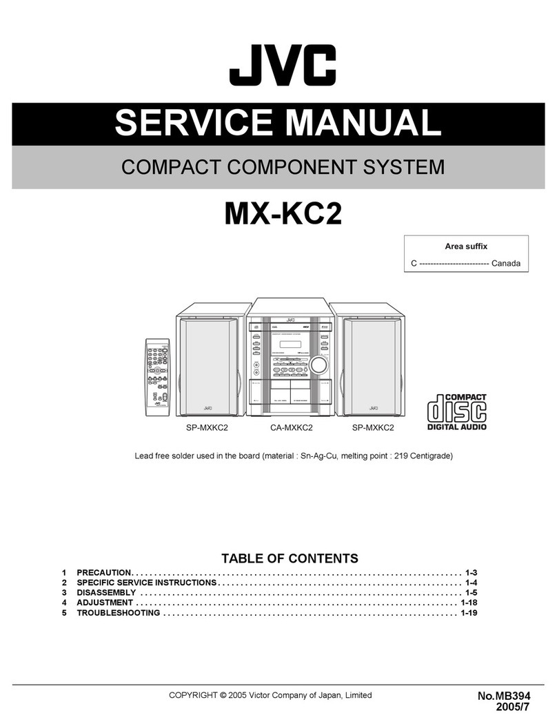
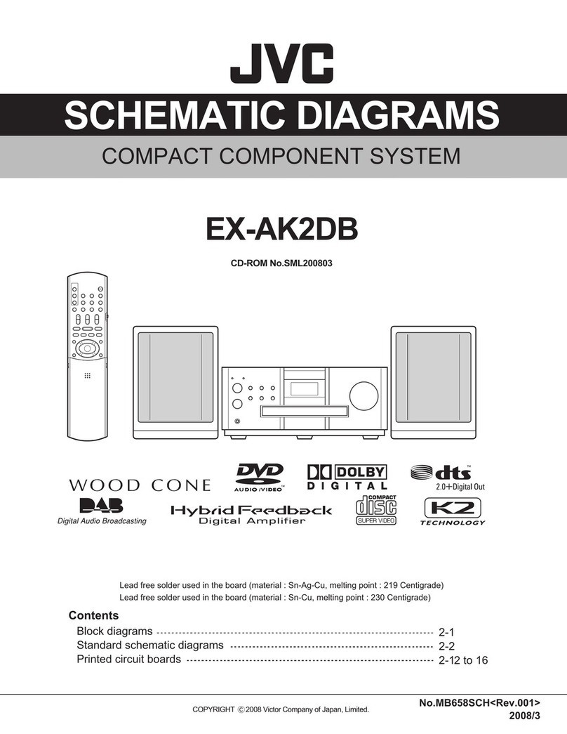
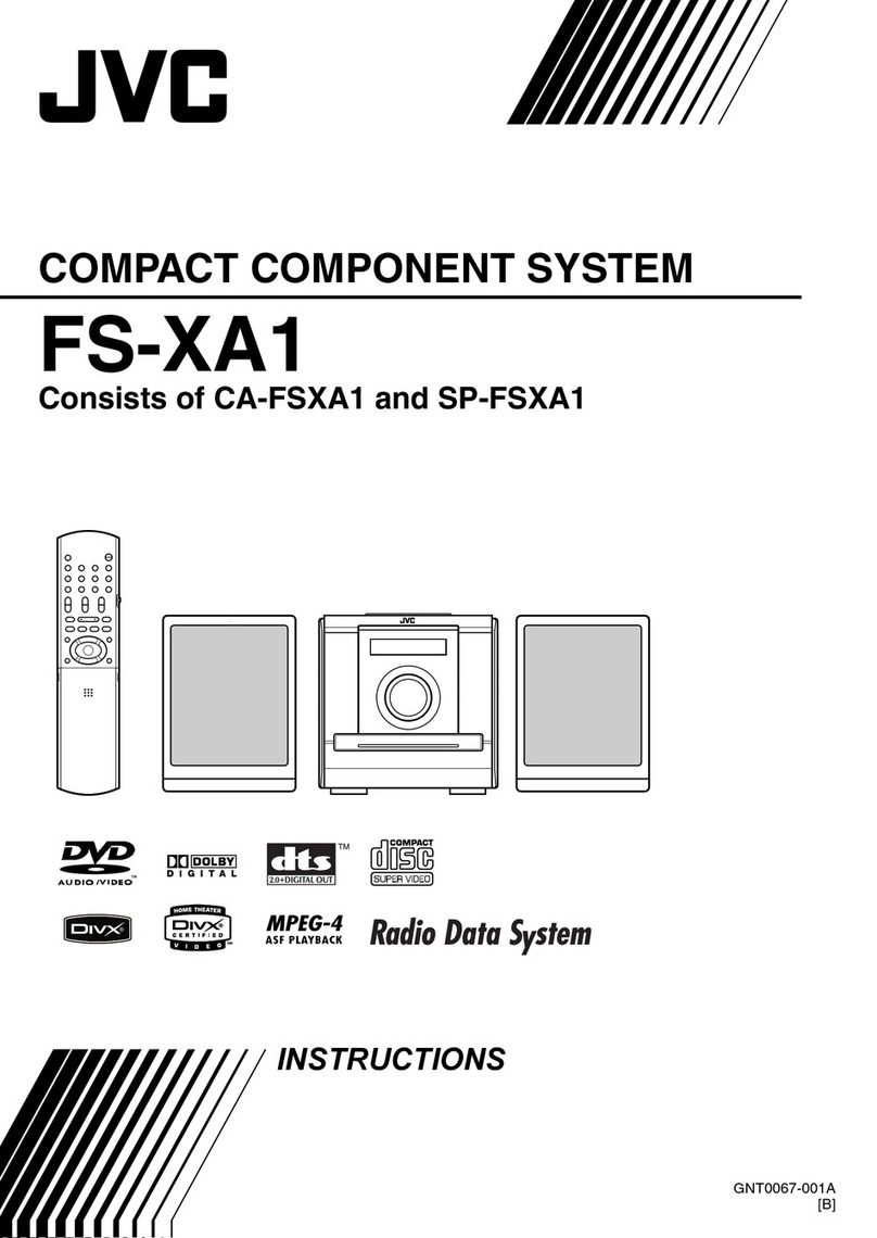
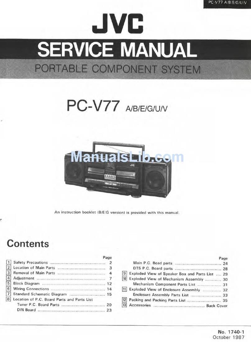
JVC EX-A1 User manual

SERVICEMANUAL
COPYRIGHT©2005VictorCompanyof Japan,Limited
No.MB349
2005/1
COMPACTCOMPONENTSYSTEM
MB34920051
EX-A1
TABLEOFCONTENTS
1PRECAUTION... ... .... ... .. .... .. ... ... ... .... ... .. ... ... ... .. .... .. ...... ... .. .... ..1-3
2SPECIFICSERVICEINSTRUCTIONS.... .. .... ... .. ... ... ... .... ... .... ... .. ... ... .... .. ..1-7
3DISASSEMBLY... ... ... .. ... ... .... .. .... ... ... .. ... ... .... ... ... ... ... . ... ... ... ... .1-8
4ADJUSTMENT. .. ... .... ... ... ... .. .... .. ... ... ... .. ... . . .. ... ... ... .. .. . .. .. .... .. ..1-24
5TROUBLESHOOTING. .... ... .... .. ... ... ... .. ... .... ... ... ... .. .... .. ... ... . . .... .. ..1-28
ß®»¿-«ºº·¨
ßóóóóóóóóóóóóóóóóóóóóóóóó ß«-¬®¿´·¿
ÞóóóóóóóóóóóóóóóóóóóóóóóóóóóóóóËòÕò
Ûóóóóóóóóóó ݱ²¬·²»²¬¿´Û«®±°»
ÛÒóóóóóóóóóóó Ò±®¬¸»®²Û«®±°»
ÛÊóóóóóóóóóóóóó Û¿-¬»®²Û«®±°»
ÛÛóóóóóóóóΫ--·¿²Ú»¼»®¿¬·±²
øÍÐóÛÈßï÷øÝßóÛÈßï÷øÍÐóÛÈßï÷

1-2(No.MB349)
SPECIFICATION
DesignsandSpecificationsaresubject tochange without notice.
GeneralPowersourceAC230 V50 Hz
Powerconsumption24 W(inoperation)
1.1W(on standby)
Weight3.0kg
Externaldimensions(W IH ID)232 mm I100 mm I269 mm
DVDplayerPlayablediscsDVDVIDEO,DVDAUDIO, VCD,SuperVCD,CD,CD-R/RW
(CD, VCD, MP3,JPEG format),DVD-R/RW(video format)
Video outputColorsystemPAL
Horizontalresolution500 lines
SCARTconnector I1
AudiooutputAnalog soundoutputSpeakers I260W(30W+30W)at 4 (10%THD)
Outputpower(IEC268-3)Fittingimpedance:4 to16
Headphones I111 mW/32
Fitting impedance:16 to1k
Subwoofer I1500mVrms/10k
DigitalsoundoutputOptical I1-21dBmto-15 dBm
OtheroutputAV COMPULINK I2(Ø3.5)
AudioinputSoundinputAUX I1
Level1250 mV/50k
Level2500 mV/50k
TunerFMtunerReceiving frequency87.5MHzto108.0MHz
Antenna75 -unbalancedtype
AMtunerReceiving frequency522 kHzto1629 kHz
AntennaExternalantenna jack(loop antenna)
SpeakerType1-waybass-reflextype Magneticallyshielded type
Speaker8cmcone I1
Powerhandling capacity30 W
Impedance4
Soundpressurelevel81 dB/Wm
Dimension (W IH ID)120mm I161mm I239 mm
Weight(1unit)1.6kg

(No.MB349)1-3
SECTION1
PRECAUTION
1.1SafetyPrecautions
(1)Thisdesignofthisproductcontainsspecialhardwareand
manycircuitsand componentsspeciallyforsafetypurpos-
es. Forcontinued protection,no changesshouldbe made
totheoriginaldesign unless authorized inwritingbythe
manufacturer.Replacementpartsmustbe identicalto
thoseused inthe originalcircuits.Servicesshouldbe per-
formed byqualifiedpersonnelonly.
(2)Alterationsofthedesignorcircuitryofthe productshould
notbe made. Anydesign alterationsoftheproductshould
notbe made.Anydesign alterationsoradditionswill void
the manufacturerswarrantyandwillfurtherrelievethe
manufactureofresponsibilityforpersonalinjuryorproperty
damageresultingtherefrom.
(3)Manyelectricaland mechanicalpartsintheproductshave
specialsafety-relatedcharacteristics.Thesecharacteris-
ticsareoften notevidentfromvisualinspectionnorcan the
protectionafforded bythemnecessarilybe obtained byus-
ing replacementcomponentsrated forhighervoltage,watt-
age,etc.Replacementpartswhichhavethesespecial
safetycharacteristics areidentifiedinthe PartsList ofSer-
viceManual.Electricalcomponentshaving suchfeatures
areidentified byshading on theschematicsandby()on
the PartsListinthe ServiceManual.The useofasubstitute
replacement whichdoesnot havethe samesafetycharac-
teristicsasthe recommended replacementpartsshownin
the PartsListofServiceManualmaycreateshock,fire,or
otherhazards.
(4)The leadsinthe productsarerouted and dressedwithties,
clamps,tubings,barriersandtheliketobeseparated from
liveparts,hightemperatureparts,moving partsand/or
sharpedgesfortheprevention ofelectricshockandfire
hazard. When serviceisrequired,the originallead routing
anddressshouldbeobserved,and itshouldbe confirmed
thattheyhavebeen returned tonormal,afterreassem-
bling.
(5)Leakageshock hazardtesting
Afterreassembling the product,alwaysperforman isola-
tioncheckon the exposedmetalpartsofthe product(an-
tenna terminals,knobs,metalcabinet,screwheads,
headphone jack,controlshafts,etc.)tobe surethe product
issafetooperatewithoutdangerofelectricalshock.Donot
usealine isolation transformerduring thischeck.
Plugthe AClinecorddirectlyintotheACoutlet. Using a
"LeakageCurrent Tester",measuretheleakage current
fromeachexposed metalpartsofthecabinet,particular-
lyanyexposedmetalparthaving areturnpathtothe
chassis,toaknowngood earthground.Anyleakagecur-
rentmustnotexceed 0.5mAAC(r.m.s.).
Alternatecheck method
Plug theACline corddirectlyintothe ACoutlet.Usean
ACvoltmeterhaving,1,000 pervolt ormoresensitivity
inthefollowing manner. Connect a1,500 10Wresistor
paralleledbya0.15kFAC-typecapacitorbetween an ex-
posed metalpartand aknowngoodearthground.
Measurethe ACvoltage acrossthe resistorwiththe AC
voltmeter.
Movethe resistorconnection toeachexposedmetal
part, particularlyanyexposed metalparthaving areturn
pathtothechassis, and measuretheACvoltageacross
the resistor.Now,reversethe plug inthe ACoutletand
repeateachmeasurement. Vo
ltagemeasured anymust
notexceed0.75 VAC(r.m.s.).Thiscorrespondsto0.5
mAAC(r.m.s.).
1.2Warning
(1)Thisequipmenthasbeen designedand manufactured to
meetinternationalsafetystandards.
(2)It isthe legalresponsibilityofthe repairertoensurethat
thesesafetystandardsaremaintained.
(3)Repairsmustbe madeinaccordancewiththe relevant
safetystandards.
(4)It isessentialthatsafetycriticalcomponentsarereplaced
byapproved parts.
(5)If mainsvoltageselectoris
provided,check setting forlocal
voltage.
1.3Caution
Burrsformedduring moldingma
ybeleftoveron someparts
ofthechassis.
Therefore,pay attention tosuchburrsinthecase ofpre-
forming repairofthissystem.
1.4Criticalpartsforsafety
Inregardwithcomponentparts
appearing on the silk-screen
printedside (partsside)ofthe
PWBdiagrams,the partsthat are
printedoverwithblacksuchasthe resistor(),diode ()
and ICP()oridentified bythe ""marknearbyarecritical
forsafety.When replacing them, be suretousethe partsofthe
sametype and ratingasspecified bythe manufacturer.
(Thisregulation dosenotExceptthe Jand Cversion)
Ù±±¼»¿®¬¸¹®±«²¼
д¿½» ¬¸·-
°®±¾» ±²
»¿½¸ »¨°±-»¼
³»¬¿´°¿®¬ò
ßÝÊÑÔÌÓÛÌÛÎ
øØ¿ª·²¹ ïððð
±¸³-ñª±´¬-ô
±® ³±®»-»²-·¬·ª·¬§÷
ïëððïðÉ
ðòïëÚ ßÝÌÇÐÛ
1-4(No.MB349)
1.5SafetyPrecautions(U.Konly)
(1)Thisdesign ofthisproductcontainsspecialhardwareandmanycircuitsand componentsspeciallyforsafetypurposes.Forcon-
tinued protection, no changesshouldbemade tothe originaldesign unlessauthorized inwriting bythemanufacturer. Replace-
mentpartsmustbeidenticaltothoseusedintheoriginalcircuits.
(2)Anyunauthoriseddesign alterationsoradditionswill voidthe manufacturer'sguarantee;furthermorethemanufacturercannot
acceptresponsibilityforpersonalinjuryorpropertydamage resulting therefrom.
(3)Essentialsafetycriticalcomponentsareidentified by()on the PartsList andbyshadingon the schematics, and must never
be replaced bypartsotherthan thoselisted inthe manual. Pleasenotehoweverthat manyelectricaland mechanicalpartsin
the product havespecialsafetyrelated characteristics.Thesecharacteristicsareoften not evident fromvisualinspection. Parts
otherthan specified bythemanufacturermaynot havethe samesafetycharacteristics asthe recommendedreplacement parts
showninthePartsList ofthe ServiceManualand maycreateshock,fire, orotherhazards.
(4)The leadsinthe productsarerouted and dressed withties,clamps,tubings,barriersandtheliketobe separated fromliveparts,
high temperatureparts,moving partsand/orsharpedgesforthe prevention ofelectricshock and firehazard. When serviceis
required,the originalleadroutingand dressshouldbe observed,and itshouldbe confirmed thattheyhavebeen returned to
normal,afterre-assembling.
1.5.1Warning
(1)Serviceshouldbe performedbyqualifiedpersonnelonly.
(2)Thisequipmenthasbeendesigned and manufactured tomeetinternationalsafetystandards.
(3)Itisthelegalresponsibilityofthe repairertoensurethatthesesafetystandardsaremaintained.
(4)Repairsmust be madeinaccordancewiththerelevantsafetystandards.
(5)Itisessentialthat safetycriticalcomponentsarereplaced byapproved parts.
(6)Ifmainsvoltage selectorisprovided,check settingforlocalvoltage.
Þ«®®- º±®³»¼ ¼«®·²¹ ³±´¼·²¹ ³¿§ ¾»´»º¬±ª»® ±² -±³» °¿®¬-±º¬¸»½¸¿--·-ò̸»®»º±®»ô
°¿§ ¿¬¬»²¬·±² ¬±-«½¸ ¾«®®-·² ¬¸»½¿-»±º°®»º±®³·²¹ ®»°¿·®±º¬¸·--§-¬»³ò

(No.MB349)1-5
1.6Preventing staticelectricity
Electrostaticdischarge(ESD), whichoccurswhen staticelectricitystored inthe body,fabric,etc. isdischarged, candestroy
the laser
diode inthe traverseunit (opticalpickup).Takecaretopreventthiswhen performingrepairs.
1.6.1Grounding topreventdamagebystaticelectricity
Staticelectricityintheworkarea can destroythe opticalpickup(laserdiode)indevicessuchaslaserproducts.
Becarefultousepropergrounding inthearea whererepairsarebeing performed.
(1)Groundthe workbench
Ground the workbenchbylaying conductivematerial(suchasaconductivesheet)oran ironplat
eoveritbeforeplacingthe
traverseunit (opticalpickup)on it.
(2)Ground yourself
Usean anti-staticwriststrap toreleaseanystaticelectricitybuilt up inyourbody.
(3)Handlingthe opticalpickup
Inordertomaintainqualityduring transportandbeforeinsta
llation,bothsidesofthe laserdiode on the replacementoptica
l
pickupareshorted.Afterreplacement, returnthe shorted partstotheiroriginalcondition.
(Refertothetext.)
Donotuseatestertocheckthecondition ofthe laserdiode intheopticalpickup. The tester'sinternalpowersourcecanea
sily
destroythe laserdiode.
1.7Handlingthetraverseunit(opticalpickup)
(1)Donot subjectthe traverseunit(opticalpickup)tostrong shocks,asitisasensitive,complexunit.
(2)Cutoffthe shorted partoftheflexiblecableusing nippers, etc.afterreplacing the opticalpickup.Forspecificdetails
, refertothe
replacement procedureinthe text.Removethe anti-staticpinwhenreplacing the traverseunit. Becarefulnot totaketoo long
a
timewhen attaching ittothe connector.
(3)Handlethe flexiblecablecarefullyasit maybreakwhensubjected tostrong force.
(4)I tisnotpossibletoadjustthe semi-fixedresistorthat adjuststhelaserpower.Donotturnit.
1.8Attentionwhentraverse unitisdecomposed
*Pleasereferto"Disassemblymethod"inthetextforthepickup unit.
Applysoldertothe shortland sectionsbeforetheflexiblewireisdisconnected fromthe connectoon theservoboard.(Ifthe
flexible
wireisdisconnected withoutapplying solder,thepickupmaybedestroyed bystaticelectricity.)
Inthe assembly,be suretoremovesolderfromthe shortlandsectionsafterconnecting theflexiblewire.
ïÓ
ݱ²¼«½¬·ª»³¿¬»®·¿´
ø½±²¼«½¬·ª»-¸»»¬÷±®·®±² °¿´¿¬»
ø½¿°¬·±²÷
ß²¬·ó-¬¿¬·½©®·-¬-¬®¿°
͸±®¬´¿²¼ -»½¬·±²
Ý¿®¼©·®»
Ì®¿ª»®-»³»½¸¿²·-³¿--»³¾´§
°·½µ«°

1-6(No.MB349)
1.9Importantforlaserproducts
ïòÝÔßÍÍ ïÔßÍÛÎÐÎÑÜËÝÌ
îòÜßÒÙÛÎæ ײª·-·¾´»´¿-»®®¿¼·¿¬·±²©¸»²±°»²¿²¼·²¬»®
´±½µ º¿·´»¼ ±®¼»º»¿¬»¼òߪ±·¼¼·®»½¬»¨°±-«®»¬±¾»¿³ò
íòÝßËÌ×ÑÒæ ̸»®»¿®»²± -»®ª·½»¿¾´»°¿®¬-·²-·¼» ¬¸»
Ô¿-»®Ë²·¬òܱ²±¬¼·-¿--»³¾´»¬¸» Ô¿-»®Ë²·¬òλ°´¿½»
¬¸» ½±³°´»¬»Ô¿-»®Ë²·¬ ·º·¬³¿´º«²½¬·±²-ò
ìòÝßËÌ×ÑÒæ ̸» ÝÜôÓÜ¿²¼ ÜÊܰ´¿§»®«-»-·²ª·-·¾´»
´¿-»®®¿¼·¿¬·±² ¿²¼·-»¯«·°°»¼ ©·¬¸-¿º»¬§-©·¬½¸»-©¸·½¸
°®»ª»²¬ »³·--·±²±º®¿¼·¿¬·±²©¸»²¬¸» ¼®¿©»®·-±°»²¿²¼
¬¸» -¿º»¬§·²¬»®´±½µ-¸¿ª»º¿·´»¼ ±®¿®»¼»º»¿¬»¼ò׬·-
¼¿²¹»®±«-¬±¼»º»¿¬¬¸» -¿º»¬§-©·¬½¸»-ò
ëòÝßËÌ×ÑÒæ ׺-¿º»¬§-©·¬½¸»-³¿´º«²½¬·±²ô¬¸» ´¿-»®·-¿¾´»
¬±º«²½¬·±²ò
êòÝßËÌ×ÑÒæ Ë-»±º½±²¬®±´-ô¿¼¶«-¬³»²¬-±®°»®º±®³¿²½»±º
°®±½»¼«®»-±¬¸»®¬¸¿² ¬¸±-»-°»½·º·»¼¸»®»·²³¿§®»-«´¬·²
¸¿¦¿®¼±«-®¿¼·¿¬·±²»¨°±-«®»ò
ÎÛÐÎÑÜËÝÌ×ÑÒßÒÜ ÐÑÍ×Ì×ÑÒÑÚÔßÞÛÔÍ
ÝßËÌ×ÑÒ æÊ·-·¾´» ¿²¼ ײª·-·¾´»
´¿-»® ®¿¼·¿¬·±² ©¸»² ±°»² ¿²¼
·²¬»®´±½µ º¿·´»¼±®¼»º»¿¬»¼ò
ßÊÑ×ÜÜ×ÎÛÝÌÛÈÐÑÍËÎÛÌÑ
ÞÛßÓò ø»÷
ÊßÎÒ×ÒÙ æÍ§²´·¹ ±½¸
±-§²´·²¹ ´¿-»®-¬®;´²·²¹ ²<®
¼»²*°°²¿-±½¸-°<®®»²<®
«®µ±°°´¿¼ò Þ»¬®¿µ¬¿ »¶
-¬®;´»²òø-÷
ÊßÎÑ æ ߪ¿¬¬¿»--¿ ¶¿ -«±¶¿´«µ·¬«-
±¸·¬»¬¬«²¿¬¿·ª·¿´´·-»²¿ ±´»¬¿´¬¬··²¿
²<µ§ª<´´» ¶¿ ²<µ§³<¬¬*³<´´»
´¿-»®-<¬»·´§´´»òÊ<´¬<-<¬»»²
µ±¸¼·-¬«³·-¬¿ -«±®¿¿²·¬-»»-·ò øº÷
ßÜÊßÎÍÛÔ æÍ§²´·¹ ±¹«-§²´·¹
´¿-»®-¬®;´·²¹²;®³¿-µ·²»²»®
;¾»²»´´»®·²¬»®´±½µ»²º»¶»´»®ò
˲¼¹;¼·®»µ¬»»µ-°±²»®·²¹¬·´
-¬®;´·²¹òø¼÷
д»¿-» «-» »²±«¹¸ ½¿«¬·±² ²±¬¬±
-»» ¬¸»¾»¿³ ¼·®»½¬´§±®¬±«½¸·¬
·²½¿-» ±º¿²¿¼¶«-¬³»²¬±®±°»®¿¬·±²
½¸»½µò
ÝÔßÍÍ ï
ÔßÍÛÎÐÎÑÜËÝÌ
ÝßËÌ×ÑÒ æÊ·-·¾´» ¿²¼ ײª·-·¾´»
´¿-»® ®¿¼·¿¬·±²©¸»² ±°»²¿²¼
·²¬»®´±½µ º¿·´»¼ ±® ¼»º»¿¬»¼ò
ßÊÑ×ÜÜ×ÎÛÝÌÛÈÐÑÍËÎÛÌÑ
ÞÛßÓò ø»÷
ÊßÎÒ×ÒÙ æÍ§²´·¹ ±½¸
±-§²´·²¹ ´¿-»®-¬®;´²·²¹ ²<®
¼»²*°°²¿- ±½¸ -°<®®»² <®
«®µ±°°´¿¼òÞ»¬®¿µ¬¿ »¶
-¬®;´»²òø-÷
ÊßÎÑ æ ߪ¿¬¬¿»--¿ ¶¿ -«±¶¿´«µ·¬«-
±¸·¬»¬¬«²¿¬¿·ª·¿´´·-»²¿ ±´»¬¿´¬¬··²¿
²<µ§ª<´´» ¶¿ ²<µ§³<¬¬*³<´´»
´¿-»®-<¬»·´§´´»òÊ<´¬<-<¬»»²
µ±¸¼·-¬«³·-¬¿ -«±®¿¿²·¬-»»-·ò øº÷
ßÜÊßÎÍÛÔ æÍ§²´·¹ ±¹«-§²´·¹
´¿-»®-¬®;´·²¹²;®³¿-µ·²»²»®
;¾»²»´´»®·²¬»®´±½µ»²º»¶»´»®ò
˲¼¹;¼·®»µ¬»»µ-°±²»®·²¹¬·´
-¬®;´·²¹òø¼÷
ÉßÎÒ×ÒÙÔßÞÛÔ

(No.MB349)1-7
SECTION2
SPECIFICSERVICEINSTRUCTIONS
The DVDmechanismwasrunning changed.
The labelisadded tothe lowerleft on the backof acenterunit asthe discernment method of aDVDmechanismfromgoodsappea
r-
ance.
Pleaserefertoeachmodeland thefollowingmanualsaboutthe goodswithwhichthe labelisnotstuckon the position ofafigure.
EX-A1B,E, ENversionMB156
EX-A1EE,EV, AversionMB181
ïìðð
Ü·-½»®²³»²¬ ´¿¾»´¿¬¬¿½¸³»²¬ °±-·¬·±²

1-8(No.MB349)
SECTION3
DISASSEMBLY
3.1Mainbodysection
3.1.1Removing thetopcover
(See Fig.1)
(1)Fromthe top side ofthe mainbody,removethe fourscrews
Aattaching thetop cover.
Fig.1
ß ß
ß
̱°½±ª»®

(No.MB349)1-9
3.1.2Removing theALpanel LandALpanelR
(See Figs.2to7.)
Removethe top cover.
(1)Removethe twoscrews B,screw Cand screw C' attaching
the bridgeA.(See Fig.2.)
Reference:
When attaching the screw C' attachthe lugwirewithit.
(See Fig.2.)
(2)Removethe twoscrews Cattaching thebridge B.(See
Fig.2.)
(3)Removethe twoscrews C' attaching the bridgeC.(See
Fig.2.)
(4)Fromthebackside ofthemainbody,removethe three
screws Dattaching the bridgeC.(See Fig.3.)
Reference:
When attaching the screws C' attachthe lug wireswith
them.(See Fig.2.)
(5)Fromthe topside ofthe mainbody,removethe twoscrews
Eattaching the ALpanelLandALpanelR. (See Fig.4.)
(6)Fromthebottomside ofthemainbody,removethethree
screws Fattachingthe wood bar.(See Fig.5.)
(7)Removethesixscrews Gand twoscrews Hattachingthe
ALpanelLand ALpanelR. (See Fig.6.)
(8)Removethe ALpanelLand ALpanelRinthedirection of
the arrow2whileextending thebacksection oftheALpan-
elLand ALpanelRinthe direction ofthe arrow1.(See
Fig.7.)
Fig.2
Fig.3
Fig.4
Ô«¹©·®»-
ÞÞ®·¼¹»ß
Ý
Ýù
Ýù
Ý
Ý
Ýù
Þ®·¼¹»Þ
Þ®·¼¹»Ý
Ô«¹©·®»
Ü
Û
ßÔ°¿²»´Î
ßÔ°¿²»´Ô

1-10 (No.MB349)
Fig.5
Fig.6
Fig.7
Ú
ɱ±¼¾¿
®
ßÔ°¿²»´Ô
ÙÙ
ØØ
ßÔ°¿²»´Î
ßÔ°¿²»´ÔßÔ°¿²»´Î
ïïïï
î î

(No.MB349)1-11
3.1.3Removing thefrontpanelassembly
(SeeFig.8)
Removethe top cover, ALpanelLandALpanelR.
(1)Removing the three screws Jattaching the frontpanelas-
sembly. (SeeFig.8.)
(2)Releasetheclaws aattachingthefrontpanelassembly
andremovethe frontpanelassemblyinthe direction ofthe
arrow. (SeeFig.8.)
Note:
When attaching the frontpanelassembly,confirmthatthe con-
nector CN804 on thefrontboardisdisconnected inthecon-
nector CN704 on the micomboardcertainly.
Fig.8
Ö
¿¿
Ú®±²¬ °¿²»´¿--»³¾´
§
Ö
ÝÒèðì
ÝÒéðì

1-12 (No.MB349)
3.1.4Removing therearpanel
(See Fig.9.)
[ForAversion]
Fromtheback sideofthe mainbody,removethe sixteen
screws Kand screw Lattachingthe rearpanel.
[ForB/E/EN/EV/EE version]
Fromthebacksideofthe mainbody,removethefifteen
screws Kand screw Lattachingthe rearpanel.
3.1.5Removing theswitching powerunit
(See Figs.9and 10)
Removethetopcover,ALpanelLandALpanelR.
(1)Fromthebackside ofthe mainbody, removethe screw L
attaching the switching powerunit. (See Fig.9.)
(2)Fromtherightside ofthemainbody,disconnectthe wire
fromthe connector CN201 on themainboard.(See
Fig.10.)
(3)Removethe screw Mattaching the switching powerunit.
(See Fig.10.)
(4)Fromthetop side ofthe switchingpowerunit,removethe
spacerfixing the lug wire.(See Fig.10.)
(5)Takeoutthe switching powerunitfromthemainbodyinthe
direction of the arrow.(See Fig.10.)
Fig.9
Fig.10
Õ
ÕÔ Î»¿®°¿²»´
Õ
ÕÔ Î»¿®°¿²»´
ÅÚ±®ßª»®-·±²Ã
ÅÚ±®ÞñÛñÛÒñÛÊñÛÛª»®-·±²Ã
ÓÍ©·¬½¸·²¹°±©»®«²·¬
ÝÒîðï Ó¿·²¾±¿®¼
É·®»
Ͱ¿½»®
Ô«¹©·®»

(No.MB349)1-13
3.1.6Removing thetuner
(See Figs.11and12)
Removethetop coverandrearpanel.
(1)Fromthe topside ofthe mainbody,removethe twoscrews
Nattachingthe bridgeC. (SeeFig.11.)
Reference:
When attaching the screws N,attachthe lug wireswith
them.(See Fig.11.)
(2)Releasetheclaws bofthe tunerholderand takeoutthe
tunerfromthemainbody.(SeeFig.12.)
(3)Disconnectthe cardwirefromthe connector CN1 onthe
tuner.(See Fig.12.)
Fig.11
Fig.12
3.1.7Removing theheadphoneboard
(SeeFig.13)
Removethetop cover,ALpanelL, ALpanelRand front panel
assembly.
(1)Fromthe leftsideofthemainbody,disconnectthe wire
fromtheconnector CN401 onthemainboard.
(2)Removethescrew Pattaching theheadphoneboard.
(3)Removethe engagementsection ctowardthisside,re-
movethe headphone boardfromthe joint dinthe direction
of thearrow.
Fig.13
Ô«¹©·®» Þ®·¼¹»Ý
Ò
Ò
Ô«¹©·®»
¾Ì«²»®
¾
Ý¿®¼©·®»
ÝÒï
¼
Ø»¿¼°¸±²»¾±¿®¼
ÝÒìðï
Ó¿·²¾±¿®¼
Ð
½

1-14 (No.MB349)
3.1.8Removing themainboard
(See Figs.14 and 15)
Removethetop cover,ALpanelL,ALpanelR, rearpaneland
switching powerunit.
Reference:
Removethe frontpanelassemblyasrequired.
(1)Fromthe topsideofthe mainbody,disconnectthecard
wiresfromthe connectors(CN202 and CN204)on the
mainboard.(SeeFig.14.)
(2)Disconnectthewiresfromthe connectors(CN205 and
CN401)onthe mainboard.(See Fig.14.)
(3)Disconnect thewirefromthe connector CN706 on themi-
comboard.(See Fig.14.)
(4)Disconnectthewiresfromthe connectors(CN310 and
CN312)on the digitalamplifierboardassembly.(See
Fig.14.)
(5)Removethescrew Qattachingthelug wiretothebracket
A.(See Fig.14.)
(6)Disconnectthe lug wirefromTP201 on the mainboard.
(See Fig.14.)
(7)Removethe spacerfixing thelug wire.(See Fig.15.)
(8)Removethefourscrews Rattachingthe mainboardand
removethe mainboardfromthemainbody.(See Fig.15.)
Reference:
When attaching the mainboard, attachthe screws Rafterfit-
tingthe holesofthemainboardtothe joints eand fofthe main
body.(See Fig.15.)
Fig.14
Fig.15
Ó¿·²¾±¿®¼
Ó·½±³¾±¿®¼
ÝÒîðì
ÝÒîðë
ÝÒîðî
ÝÒìðï
ÝÒíïî
ÝÒíïð
É·®»
Ý¿®¼©·®»
Ý¿®¼©·®»
É·®»
É·®»-
Ü·¹·¬¿´¿³°´·º·»®
¾±¿®¼¿--»³¾´§
ÝÒéðê
Ô«¹©·®»
Ï
Þ®¿½µ»¬
ß
ÌÐîðï
Ó¿·²¾±¿®¼
ÌÐîðï
Ô«¹©·®»
Ó¿·²¾±¿®¼
Î
Î
Î
Ͱ¿½»®
º
»
Ô«¹©·®»

(No.MB349)1-15
3.1.9Removing themicomboard
(See Figs.16and17)
Removethetop cover, ALpanelL, ALpanelR,front panelas-
sembly,rearpanel,switching powerunitand mainboard.
(1)Fromthe topsideofthemainbody,disconnectthe card
wiresfromthe connectors(CN631 and CN701)on the mi-
comboard.(See Fig.16.)
(2)Disconnectthe cardwirefromthe connector CN705 on the
micomboardand takeoutthetunerafterreleasing the
claws gofthetunerholder. (SeeFig.16.)
Reference:
Removethe tunerasrequired.
(3)Disconnectthe wirefromthe connector CN311 on thedig-
italamplifierboardassembly.(SeeFig.16.)
(4)Disconnectthe cardwirefromthe connector CN611 on the
mainboard.(See Fig.17.) [ForAversion]
(5)Disconnectthe cardwirefromthe connector CN601 on the
mainboard.(See Fig.17.) [ForB/E/EN/EV/EE version]
(6)Removethe twoscrews Sand screw S' attaching themi-
comboard.(See Fig.17.)
Reference:
Whenattaching the screw S',attachthe bracketDwithit.
(See Fig.17.)
Whenattaching the micomboard,attachthe screw Sand
screw S' afterfitting theholesof the mainboardtothe joints
(h,i,j,k)of the mainbody.(See Fig.17.) Fig.16
Fig.17
Ý¿®¼©·®»-
Ý¿®¼©·®»
ÝÒêíï
ÝÒéðï
ÝÒíïï
É·®»
Ì«²»®
ÝÒéðë
¹
Ì«²»®¸±´¼»®
Ü·¹·¬¿´¿³°´·º·»®¾±¿®¼¿--»³¾´§
Ó·½±³¾±¿®¼
Ó·½±³¾±¿®¼
Þ®¿½µ»¬Ü
¸
Íù
Ó·½±³
¾±¿®¼
·
Ó·½±³¾±¿®¼
¶
Í
Í
Ó·½±³¾±¿®¼
µ
ÝÒêðï
Ý¿®¼©·®»

1-16 (No.MB349)
3.1.10Removing thedigitalamplifierboard
(See Figs.18 to20)
Removethetop cover, ALpanelL, ALpanelR, frontpanelas-
sembly, rearpanel,switchingpowerunit,mainboardand mi-
comboard.
(1)Fromthe backside ofthe mainbody, disconnectthe card
wirefromthe connector CN313 on the digitalamplifier
boardassembly.(SeeFig.18.)
Reference:
When connecting the wire,connectthewiretoconnector
CN313 onthe digitalamplifierboardassemblyafterpass
itthroughthe section moftheside coverL.(See Fig.18.)
(2)Fromthetop sideofthe mainbody,removethe twoscrews
Tand twoscrews Uattaching the bracketC.(See Fig.18.)
(3)Takeout thebracketCwiththeheadphoneboardfromthe
mainbody.
Reference:
When attaching thebracket Ctothe bottomchassis,at-
tachitafterfittingtheholestothe projectionsnofthe bot-
tomchassis. (SeeFig.18.)
(4)Takeoutthe digitalamplifierboardassembly.
(5)Releasethe joints(p,q,r)ofthe deuscaseAand deuscase
B,andremovethedeuscaseAinthedirectionofthe ar-
row.(SeeFig.19.)
(6)Removethe screw Vattaching the heatsink. (See Fig.20.)
(7)Removethe solderfromthe soldered sections(s,t)attach-
ing the digitalamplifierboardtothe deuscaseBand bend
the joints(u,v)inthedirectionofthearrow. (SeeFig.20.)
(8)Takeoutthe digitalamplifierboardfromthe deuscaseB.
Reference:
When attaching the digitalamplifierboardtothe deuscaseB,
fitthejoints(u,v,w,x)ofthe deuscaseBtotheholesofthedig-
italamplifierboard.(See Fig.20.)
Fig.18
Fig.19
Fig.20
ÝÒíïí
É·®»
³
Í·¼»½±ª»®Ô Ì
Ì
Ë
Ü·¹·¬¿´¿³°´·º·»®¾±¿®¼¿--»³¾´§
Þ®¿½µ»¬Ý
Ë
Ø»¿¼°¸±²»¾±¿®¼
²
Þ±¬¬±³½¸¿--·-
°
®
¯
Ü»«-½¿-»ß
Ü»«-½¿-»Þ
Ê
Ü·¹·¬¿´¿³°´·º·»®¾±¿®¼
Ø»¿¬ -·²µ
-
«
ª
¨
Ü»«-½¿-»Þ
¬
©

(No.MB349)1-17
3.1.11Removing thespeakerterminalboard
(SeeFig.21.)
Removethetop cover, ALpanelL, ALpanelR,front panelas-
sembly,the rearpanel,switching powerunit,mainboardand
micomboard.
(1)Fromthe backside ofthe mainbody,disconnectthe wire
fromthe connector CN313 on the digitalamplifierboardas-
sembly.
Reference:
When connecting the wire,connectthewiretoconnector
CN313 onthe digitalamplifierboardassemblyafterpass
itthrough the section yof the side coverL. (See Fig.21.)
(2)Fromthe top side ofthemainbody,removethescrew W
attaching thespeakerterminalboard.
Reference:
When attaching the speakerterminalboard,attachthe
screw Wafterfitting the holeofthe speakerterminal
boardtothe joint zofthe sidecoverR.
3.1.12Removing thecomponentvideoterminal board
(SeeFig.21)[ForAversion]
Removethetop cover, ALpanelL, ALpanelR,front panelas-
sembly,rearpanel,switching powerunit,mainboardand mi-
comboard.
Fromthe topside ofthe mainbody,removethe screw Xat-
taching the componentvideo terminalboard.
Reference:
When attaching thecomponentvideoterminalboard,attach
the screw Xafterfittingthe holeofthecomponentvideo termi-
nalboardtothe joint aa ofthe side coverL.
Fig.21
3.1.13Removing thescartterminalboard
(SeeFig.22)[ForB/E/EN/EV/EE version]
Removethetop cover, ALpanelL, ALpanelR,front panelas-
sembly,rearpanel,switching powerunit,mainboardand mi-
comboard.
Fromthe topside ofthe mainbody,removethe screw Xat-
taching thescartterminalboard.
Reference:
When attaching thescartterminalboard,attachthe screw X
afterfittingtheholeofthescartterminalboardtothe joint aa
ofthe side coverL.
Fig.22
É
Í·¼»½±ª»®Î
È
Í·¼»½±ª»®Ô
Ü·¹·¬¿´¿³°´·º·»®¾±¿®¼¿--»³¾´§
¿¿
Ͱ»¿µ»®¬»®³·²¿´¾±¿®¼
¦
§
ݱ³°±²»²¬ª·¼»±¬»®³·²¿´¾±¿®¼
ÝÒíïí
É·®»
É
Í·¼»½±ª»®Î
È
Í·¼»½±ª»®Ô
Ü·¹·¬¿´¿³°´·º·»®¾±¿®¼¿--»³¾´§
¿¿
Ͱ»¿µ»®¬»®³·²¿´¾±¿®¼
¦
§
ͽ¿®¬ ¬»®³·²¿´¾±¿®¼
ÝÒíïí
É·®»

1-18 (No.MB349)
3.1.14Removing theDVDmechanismassembly
(See Fig.23.)
Removethetop cover, ALpanelL, ALpanelR, frontpanelas-
sembly, rearpanel, switching powerunit,mainboardandthe
micomboard.
(1)Fromthetop side ofthe mainbody,removethe three
screws Yattachingthe DVDmechanismassembly.
(2)TakeouttheDVDmechanismassemblyfromthe main
body.
Fig.23
3.1.15Removing thefrontboard
(See Figs.24 and 25)
Removethe top cover, ALpanelL,ALpanelRand front panel
assembly.
(1)Fromthe frontside ofthe frontpanelassembly,pulloutthe
volumeassemblyinthe direction ofthe arrow.(See
Fig.24.)
(2)Fromthe insideofthe frontpanelassembly,removethe
ten screws Zattaching the frontboard. (SeeFig.25.)
(3)Releasethe twoclaws ab oftheindicatorattaching the
frontboardandtakeoutthe frontboardfromthefrontpanel
assembly.(See Fig.25.)
Reference:
When attaching the frontboard,attachthescrews Zafterfitting
the holesofthefrontboardtothe projectionsacofthe front
panelassembly.(See Fig.25.)
Fig.24
Fig.25
ÇÇ
ÜÊܳ»½¸¿²·-³¿--»³¾´§
Ç
ʱ´«³»¿--»³¾´§
Ú®±²¬ °¿²»´¿--»³¾´§
¿½
Ú®±²¬ ¾±¿®¼
Ú®±²¬ °¿²»´¿--»³¾´§
Æ Æ
Æ
Æ
¿½
¿½
¿½
¿¾

(No.MB349)1-19
3.2DVDmechanismsection
RemovetheDVDmechanismassemblyfromthe mainbody.
(See "3.1.13 Removing theDVDmechanismassembly".)
3.2.1Removing thetray assembly
(See Figs.1to3)
(1)Fromthe rightside ofthe DVDmechanismassembly,push
the slidecamand pullthetrayassemblyoutofthe DVD
mechanismassemblyinthedirection ofthearrow.(See
Fig.1.)
(2)Fromthetop side ofthe DVDmechanismassembly,
removethetwoscrews Aattachingthe leafspring tothe
bushing and removethe leafspring. (See Fig.2.)
(3)Removethebushing ofthe trayassemblyfromthe
projection aonthe DVDmechanismassemblyand move
the trayassemblyinthe direction of the arrow. (See Fig.3.)
(4)Removetheclaw bofthe trayassemblyfromthe DVD
mechanismassemblyand takeoutthe trayassembly.(See
Fig.3.)
Fig.1
Fig.2
Fig.3
Ì®¿§¿--»³¾´§ ÜÊܳ»½¸¿²·-³¿--»³¾´§
Í´·¼»½¿³
Þ«-¸·²¹
Ô»¿º -°®·²¹ ß
ÜÊܳ»½¸¿²·-³¿--»³¾´§
Þ«-¸·²¹
Ý´¿© ¾
Ю±¶»½¬·±² ¿
Ì®¿§¿--»³¾´§
ÜÊܳ»½¸¿²·-³¿--»³¾´§

1-20 (No.MB349)
3.2.2Removing thetraverse mechanismassembly
(See Figs.4)
(1)Fromthe bottomsideofthe DVDmechanismassembly,
removethe fourscrews Battaching the traverse
mechanismassemblyand takeoutthe DVDtraverse
mechanismassemblywiththe DVDservoboard.
Fig.4
3.2.3Removing theDVDservo board
(See Figs.5and 6)
Removethetraversemechanismassembly.
(1)Fromthe side ofthetraversemechanismassembly,solder
the shortland sections con the pickup.(See Fig.5.)
(2)Fromthe bottomsideofthe traversemechanism
assembly,releasethe lock ofthe connector CN101 onthe
DVDservoboardinthe directionofthearrow1and
disconnectthe cardwire.(See Fig.6.)
Caution:
Solderthe short landsections conthe pickupbefore
disconnecting the cardwirefromthe connector CN101
on the DVDservoboard.Ifthecardwireis
disconnected withoutattachingsolder,the pickup may
be destroyed bystaticelectricity.(SeeFigs.5and 6.)
Whenattaching the DVDservoboard,besureto
removesoldersfromthe shortlandsections cafter
connecting the cardwiretothe connector CN101 on
the DVDservoboard.(SeeFigs.5and 6.)
(3)Disconnectthe cardwirefromthe connector CN201 on the
DVDservoboard.(See Fig.6.)
(4)Removethe twoscrews Cattaching theDVDservoboard.
(See Fig.6.)
(5)RemovetheDVDservoboardfromtheengagement
section dinan upwardand removethe engagement
section finthe direction 3whileremovingthe engagement
section einthe direction ofthe arrow2.(See Fig.6.)
Fig.5
Fig.6
ÜÊܳ»½¸¿²·-³¿--»³¾´§
Ì®¿ª»®-»³»½¸¿²·-³¿--»³¾´§
ÜÊÜ-»®ª±¾±¿®¼
ÞÞ
Ì®¿ª»®-»³»½¸¿²·-³¿--»³¾´§
з½µ«°
͸±®¬´¿²¼ -»½¬·±² ½
Ý¿®¼©·®» Ý¿®¼©·®»
ÜÊÜ-»®ª±¾±¿®¼
Ì®¿ª»®-»³»½¸¿²·-³¿--»³¾´§
ÝÒïðï
ÝÒîðï
ïï
îí
Ý
Ý
º
»
¼
Other manuals for EX-A1
3
Other JVC Speakers System manuals
Popular Speakers System manuals by other brands

Involve Audio
Involve Audio Y4 user manual

auna
auna UltraSonic Pulse V6-40 manual

Ssl
Ssl SMC75 user manual

Logitech
Logitech LS21 - 2.1-CH PC Multimedia Speaker Sys Specifications

GoldenEar Technology
GoldenEar Technology SuperCinema 3D Array owner's manual

Artcoustic
Artcoustic Multi Sound Bar SL owner's manual