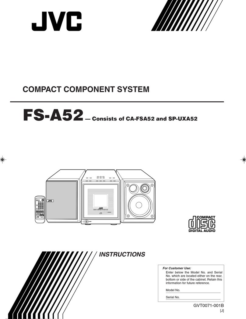
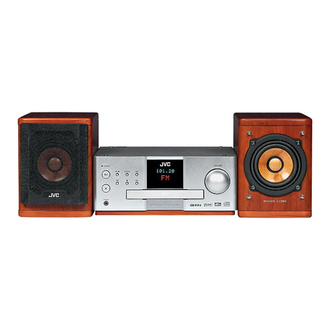
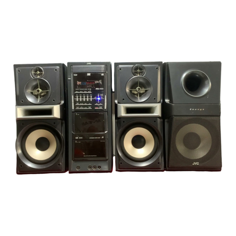
JVC UX-TB30B User manual

SERVICE MANUAL
COPYRIGHT © 2010 Victor Company of Japan, Limited No.MB725<Rev.001>
2010/3
COMPACT COMPONENT SYSTEM
MB725<Rev.001>20103SERVICE MANUAL
UX-TB30B, UX-TB30E, UX-TB30EN,
UX-TB30EV
COPYRIGHT © 2010 Victor Company of Japan, Limited
Lead free solder used in the board (material : Sn-Ag-Cu, melting point : 219 Centigrade)
TABLE OF CONTENTS
1 PRECAUTION. . . . . . . . . . . . . . . . . . . . . . . . . . . . . . . . . . . . . . . . . . . . . . . . . . . . . . . . . . . . . . . . . . . . . . . . . 1-3
2 SPECIFIC SERVICE INSTRUCTIONS . . . . . . . . . . . . . . . . . . . . . . . . . . . . . . . . . . . . . . . . . . . . . . . . . . . . . . 1-6
3 DISASSEMBLY . . . . . . . . . . . . . . . . . . . . . . . . . . . . . . . . . . . . . . . . . . . . . . . . . . . . . . . . . . . . . . . . . . . . . . . 1-6
4 ADJUSTMENT . . . . . . . . . . . . . . . . . . . . . . . . . . . . . . . . . . . . . . . . . . . . . . . . . . . . . . . . . . . . . . . . . . . . . . . 1-10
5 TROUBLESHOOTING . . . . . . . . . . . . . . . . . . . . . . . . . . . . . . . . . . . . . . . . . . . . . . . . . . . . . . . . . . . . . . . . . 1-10
AX-UXTB30
XT-UXTB30
SP-UXTB30SP-UXTB30

1-2 (No.MB725<Rev.001>)
SPECIFICATION
Designs & specifications are subject to change without notice.
Amplifier unit (AX-UXTB30)
Output Power 20 W per channel, min. RMS, driven into 6 Ωat 1 kHz with no more than 10% total harmonic distortion.
(IEC268-3)
Speakers/Impedance 6 Ω- 8 Ω
Player/tuner unit (XT-UXTB30)
Tuner section
FM tuning range 87.50 MHz - 108.00 MHz
CD player section
Measurement Condition 2W, IEC-A weighted
Dynamic range 75 dB
Signal-to-noise ratio 75 dB
Wow and flutter Immeasurable
Terminals
AUDIO IN Input sensitivity/Impedance 250 mV/50 kΩ
USB MEMORY USB specification Compatible with USB 2.0 Full-Speed
Compatible device Mass storage class
Compatible system FAT16, FAT32
Output power DC 5 V 500 mA
General
Power requirement AC 230 V , 50 Hz
Power consumption 50 W (at operation)
1.00 W or less (on standby)
Dimensions (approx.) Player/tuner unit 230 mm ×81 mm ×230 mm (W ×H ×D)
Amplifier unit 230 mm ×81 mm ×243 mm (W ×H ×D)
Mass (approx.) Player/tuner unit 1.70 kg
Amplifier unit 2.94 kg
Speakers (SP-UXTB30)
Type 2-way Bass reflex
Speaker units Tweeter 4 cm cone ×1
Woofer 10 cm cone ×1
Dimensions (approx.) 160 mm ×250 mm ×160 mm (W ×H ×D)
Mass (approx.) 1.81 kg each

(No.MB725<Rev.001>)1-3
SECTION 1
PRECAUTION
1.1 Safety Precautions
(1) This design of this product contains special hardware and
many circuits and components specially for safety purpos-
es. For continued protection, no changes should be made
to the original design unless authorized in writing by the
manufacturer. Replacement parts must be identical to
those used in the original circuits. Services should be per-
formed by qualified personnel only.
(2) Alterations of the design or circuitry of the product should
not be made. Any design alterations of the product should
not be made. Any design alterations or additions will void
the manufacturers warranty and will further relieve the
manufacture of responsibility for personal injury or property
damage resulting therefrom.
(3) Many electrical and mechanical parts in the products have
special safety-related characteristics. These characteris-
tics are often not evident from visual inspection nor can the
protection afforded by them necessarily be obtained by us-
ing replacement components rated for higher voltage, watt-
age, etc. Replacement parts which have these special
safety characteristics are identified in the Parts List of Ser-
vice Manual. Electrical components having such features
are identified by shading on the schematics and by ( ) on
the Parts List in the Service Manual. The use of a substitute
replacement which does not have the same safety charac-
teristics as the recommended replacement parts shown in
the Parts List of Service Manual may create shock, fire, or
other hazards.
(4) The leads in the products are routed and dressed with ties,
clamps, tubings, barriers and the like to be separated from
live parts, high temperature parts, moving parts and/or
sharp edges for the prevention of electric shock and fire
hazard. When service is required, the original lead routing
and dress should be observed, and it should be confirmed
that they have been returned to normal, after reassem-
bling.
(5) Leakage shock hazard testing
After reassembling the product, always perform an isola-
tion check on the exposed metal parts of the product (an-
tenna terminals, knobs, metal cabinet, screw heads,
headphone jack, control shafts, etc.) to be sure the product
is safe to operate without danger of electrical shock.Do not
use a line isolation transformer during this check.
• Plug the AC line cord directly into the AC outlet. Using a
"Leakage Current Tester", measure the leakage current
from each exposed metal parts of the cabinet, particular-
ly any exposed metal part having a return path to the
chassis, to a known good earth ground. Any leakage cur-
rent must not exceed 0.5mA AC (r.m.s.).
• Alternate check method
Plug the AC line cord directly into the AC outlet. Use an
AC voltmeter having, 1,000Ωper volt or more sensitivity
in the following manner. Connect a 1,500Ω10W resistor
paralleled by a 0.15µF AC-type capacitor between an ex-
posed metal part and a known good earth ground.
Measure the AC voltage across the resistor with the AC
voltmeter.
Move the resistor connection to each exposed metal
part, particularly any exposed metal part having a return
path to the chassis, and measure the AC voltage across
the resistor. Now, reverse the plug in the AC outlet and
repeat each measurement. Voltage measured any must
not exceed 0.75 V AC (r.m.s.). This corresponds to 0.5
mA AC (r.m.s.).
1.2 Warning
(1) This equipment has been designed and manufactured to
meet international safety standards.
(2) It is the legal responsibility of the repairer to ensure that
these safety standards are maintained.
(3) Repairs must be made in accordance with the relevant
safety standards.
(4) It is essential that safety critical components are replaced
by approved parts.
(5) If mains voltage selector is provided, check setting for local
voltage.
1.3 Caution
Burrs formed during molding may be left over on some parts
of the chassis.
Therefore, pay attention to such burrs in the case of pre-
forming repair of this system.
1.4 Critical parts for safety
In regard with component parts appearing on the silk-screen
printed side (parts side) of the PWB diagrams, the parts that are
printed over with black such as the resistor ( ), diode ( )
and ICP ( ) or identified by the " " mark nearby are critical
for safety. When replacing them, be sure to use the parts of the
same type and rating as specified by the manufacturer.
(This regulation dose not Except the J and C version)
Good earth ground
Place this
probe on
each exposed
metal part.
AC VOLTMETER
(Having 1000
ohms/volts,
or more sensitivity)
1500 10W
0.15 F AC TYPE

1-4 (No.MB725<Rev.001>)
1.5 Preventing static electricity
Electrostatic discharge (ESD), which occurs when static electricity stored in the body, fabric, etc. is discharged, can destroy the laser
diode in the traverse unit (optical pickup). Take care to prevent this when performing repairs.
1.5.1 Grounding to prevent damage by static electricity
Static electricity in the work area can destroy the optical pickup (laser diode) in devices such as laser products.
Be careful to use proper grounding in the area where repairs are being performed.
(1) Ground the workbench
Ground the workbench by laying conductive material (such as a conductive sheet) or an iron plate over it before placing the
traverse unit (optical pickup) on it.
(2) Ground yourself
Use an anti-static wrist strap to release any static electricity built up in your body.
(3) Handling the optical pickup
• In order to maintain quality during transport and before installation, both sides of the laser diode on the replacement optical
pickup are shorted. After replacement, return the shorted parts to their original condition.
(Refer to the text.)
• Do not use a tester to check the condition of the laser diode in the optical pickup. The tester's internal power source can easily
destroy the laser diode.
1.6 Handling the traverse unit (optical pickup)
(1) Do not subject the traverse unit (optical pickup) to strong shocks, as it is a sensitive, complex unit.
(2) Cut off the shorted part of the flexible cable using nippers, etc. after replacing the optical pickup. For specific details, refer to the
replacement procedure in the text. Remove the anti-static pin when replacing the traverse unit. Be careful not to take too long a
time when attaching it to the connector.
(3) Handle the flexible cable carefully as it may break when subjected to strong force.
(4) I t is not possible to adjust the semi-fixed resistor that adjusts the laser power. Do not turn it.
1M
Conductive material
(conductive sheet) or iron palate
(caption)
Anti-static wrist strap

(No.MB725<Rev.001>)1-5
1.7 Important for laser products
1.CLASS 1 LASER PRODUCT
2.CAUTION :
(For U.S.A.) Visible and/or invisible class II laser radiation
when open. Do not stare into beam.
(Others) Visible and/or invisible class 1M laser radiation
when open. Do not view directly with optical instruments.
3.CAUTION : Visible and/or invisible laser radiation when
open and inter lock failed or defeated. Avoid direct
exposure to beam.
4.CAUTION : This laser product uses visible and/or invisible
laser radiation and is equipped with safety switches which
prevent emission of radiation when the drawer is open and
the safety interlocks have failed or are defeated. It is
dangerous to defeat the safety switches.
5.CAUTION : If safety switches malfunction, the laser is able
to function.
6.CAUTION : Use of controls, adjustments or performance of
procedures other than those specified here in may result in
hazardous radiation exposure.
REPRODUCTION AND POSITION OF LABELS and PRINT
!Please use enough caution not to
see the beam directly or touch it
in case of an adjustment or operation
check.
WARNING LABEL and PRINT

1-6 (No.MB725<Rev.001>)
SECTION 2
SPECIFIC SERVICE INSTRUCTIONS
This service manual does not describe SPECIFIC SERVICE INSTRUCTIONS.
SECTION 3
DISASSEMBLY
3.1 Amplifier unit (Used model is UX-TB30E)
3.1.1 Removing the Top cover (See Fig.1, 2)
(1) Tear off the Rubber foots. (See Fig.1)
(2) Remove the four screws Aattaching the Top cover. (See
Fig.1)
Fig.1
(3) Remove the five screws Band two screws Cattaching the
Rear cover. (See Fig.2)
Fig.2
3.1.2 Removing the Main board (See Fig.3, 4)
(1) Disconnect the card wire from Display board connected to
connector CN303 of the Main board. (See Fig.3)
(2) Disconnect the connector wires from Display board con-
nected to connectors CN302 and CN305 of the Main
board. (See Fig.3)
(3) Disconnect the connector wires from Power transformer
connected to connectors CN1101 and CN1104 of the Main
board. (See Fig.3)
(4) Disconnect the connector wire from Rectifier board con-
nected to connector CN402 of the Main board. (See Fig.3)
(5) Remove the three screws Dattaching the Main board. (See
Fig.3)
Fig.3
AA
Rubber foot
B
CD
D
CN303 CN302
CN305
CN402
CN1101
CN1104

(No.MB725<Rev.001>)1-7
(6) Remove the three screws Eattaching the Heat sink. (See
Fig.4)
Fig.4
3.1.3 Removing the Rectifier board (See Fig.5)
(1) Disconnect the connector wire from Power transformer
connected to connector CN1102 of the Rectifier board.
(2) Remove the four screws Fattaching the Rectifier board.
Fig.5
3.1.4 Removing the Front panel (See Fig.6, 7)
(1) Remove the two screws Gattaching the Front panel. (See
Fig.6)
Fig.6
(2) Disengage two hooks aengaged both side of the Front
panel. (See Fig.7)
Fig.7
3.1.5 Removing the Display board (See Fig.8)
(1) Remove the five screws Hattaching the Display board.
(2) Disconnect the connector wire from Volume board con-
nected to connector CN702 of the Display board.
Fig.8
3.1.6 Removing the Rectifier board (See Fig.9)
(1) Remove the Volume knob.
(2) Remove the two screws Jattaching the Volume board.
Fig.9
E
F
F
CN1102
G
hook a
CN702
H
H
J
J

1-8 (No.MB725<Rev.001>)
3.2 CD unit (Used model is UX-TB30E)
3.2.1 Removing the Top cover (See Fig.1, 2)
(1) Tear off the Rubber foots. (See Fig.1)
(2) Remove the four screws Aattaching the Top cover. (See
Fig.1)
Fig.1
(3) Remove the five screws Band two screws Cattaching the
Rear cover. (See Fig.2)
Fig.2
3.2.2 Removing the Front panel (See Fig.3, 4, 5)
(1) Disconnect the connector wire from USB board connected
to connector CN603 of the CD board. (See Fig.3)
(2) Disconnect the connector wire from Control board connect-
ed to connector CN703 of the Equalizer board. (See Fig.3)
Fig.3
(3) Remove the two screws Dattaching the Front panel. (See
Fig.4)
Fig.4
(4) Disengage two hooks aengaged both side of the Front
panel. (See Fig.5)
Fig.5
A
A
Rubber foot
B
B
C
CN603
CN703
D
hook a

(No.MB725<Rev.001>)1-9
3.2.3 Removing the CD mechanism (See Fig.6, 7)
(1) Disconnect the connector wire from Equalizer board con-
nected to connector CN2701 of the CD door switch board.
(See Fig.6)
(2) Remove the four screws Eattaching the CD mechanism.
(See Fig.6)
Fig.6
(3) Turnover the CD mechanism, disconnect the card wire
from pickup connected to connector CN905 of the CD
board. (See Fig.7)
(4) Disconnect the connector wire from CD mechanism con-
nected to connector CN907 of the CD board. (See Fig.7)
Fig.7
3.2.4 Removing the CD board (See Fig.8)
(1) Disconnect the card wire from Equalizer board connected
to connector CN702 of the CD board.
(2) Disconnect the connector wire from Equalizer board con-
nected to connector CN901 of the CD board.
(3) Remove the three screws Fattaching the CD board.
Fig.8
3.2.5 Removing the Equalizer board (See Fig.9)
(1) Remove the three screws Gattaching the Equalizer board.
Fig.9
3.2.6 Removing the Control board (See Fig.10)
(1) Remove the five screws Hattaching the Control board.
Fig.10
3.2.7 Removing the USB board (See Fig.11)
(1) Remove the two screws Jattaching the USB board.
Fig.11
CN2701
EE
CN905
CN907
CN702
CN901
F
G
H
J

1-10 (No.MB725<Rev.001>)
SECTION 4
ADJUSTMENT
This service manual does not describe ADJUSTMENT.
SECTION 5
TROUBLESHOOTING
This service manual does not describe TROUBLESHOOTING.


(No.MB725<Rev.001>)
VSE
Printed in Japan
Victor Company of Japan, Limited
Home Entertainment Business Division Personal AV Operation 10-1,1chome,Ohwatari-machi,Maebashi-city,371-8543,Japan

3-1
PARTS LIST
* All printed circuit boards and its assemblies are not available as service parts.
- Contents -
Exploded view of general assembly and parts list (Block No.M1)
Speaker assembly and parts list (Block No.M2)
Electrical parts list (Block No.01~10)
Packing materials and accessories parts list (Block No.M3)
3- 2
3- 6
3- 7
3-13
UX-TB30B, UX-TB30E, UX-TB30EN, UX-TB30EV
AUX-TB30B
B
UX-TB30E
CUX-TB30EN
MODEL MARK
D
UX-TB30EV
MB725PAR<Rev.001>

3-2
Exploded view of general assembly and parts list
CD BOX section
CD unit section
Block No. M MM1
64
57
58
26
64
9
91
86
61
80
30
85
25
59
29
22
95
95
9
84
33
1
4
6
23
32
72
28
31
24
60
60
90
90
90
97
97
97
81
14
34
96
96
34
34
34
82
13
55
40
55
55
55
15
77
62
30
85
27
CD door switch board
a
b
f
g
g
f
c
e
e
d
d
z
c
A
A
B
b
B
Control board
CD board
USB board
EQ board
Tuner board
78
44
45
46
98
48
49 50
51

3-3
AMP unit section
k
j
m
s
s
u
u
h
w
w
r
n
n
p
p
r
h
k
j
t
t
m
The parts without symbol number are not service.
5
95
95
95
89
11
93
93
69
92
63
71
8
10
9
7
97
97
94
99
18
94
94
92
63
93 92
67 66
75
63
65
37
37
37
37
65
68
39 14
12
7
42
16
3
6
2
93
76
88
88
34
34
34
34
74 74
87
87
47
87
17
70
43
41
3
5
74
d
z
A
a
B
20
19
63
38
73
73
83
Rectifer board Main board
Display board
Volume board
board
B
79
53
36
35
56
52
54
21

3-4
General Assembly
Block No. [M][1][M][M]
Symbol No. Part No. Part Name Description Local
1 5TB-300000-002 CONTROL FRONT CABINET
2 5TB-300000-001 DISPLAY FRONT CABINET
3 5TB-300000-000 DISPLAY LENS
4 5TB-300200-001 CONTROL LENS
5 5TB-307000-001 VOLUME KNOB
6 500-081000-000 JVC MARK (x2)
7 5TB-332000-000 VFD BRACKET
8 5TB-308000-000 POWER KNOB
9 5TB-302000-000 CONTROL KNOB
10 5TB-351000-000 FUNCTION KNOB
11 5TB-386000-001 UP BACK COVER
12 5TB-386000-002 DOWN BACK COVER
13 5TB-302000-001 PEDESTAL CABINET
14 5TB-300820-000 TOP CABINET (x2)
15 5TB-349000-000 CD DOOR
16 5TB-302000-002 PEDESTAL CABINET
17 530-026200-000 LINE CORE HOLD
18 244-E05260-060 HSG 5PINS 60mm
19 244-A04300-300 WIRE 4PINS 30cm
20 244-A03780-300 WIRE 3PINS 30cm
21 235-165250-110 FFC CABLE 16PINS
22 500-047000-000 CD MECHA BRACKET
23 500-049100-000 CD PLATE
24 500-026300-000 CD MECHA COVER
25 500-036000-000 SLIDE PIECE
26 500-200000-000 CD CHUCK PLATE
27 500-048300-000 CHUCK PLATE BRACKET
28 500-000100-200 BIG GEAR
29 500-000100-100 LITTER GEAR
30 458-328840-220 RUBBER SILICON (BLACK) HARDNESS(x4)
31 356-110003-091 CD DECK
32 473-300160-500 CD MAGNET RING
33 500-100000-000 CD CHUCK HOLDER
34 5TB-303000-090 RING (x8)
35 419-030240-030 SHIELD PLATE(FRONT)
36 419-306430-030 SHIELD PLATE(BACK)
37 238-130100-602 SCREW 3x10mm PB(x5)
38 408-222193-020 METAL CABINET
39 408-TB3040-040 HEAT SINK
40 408-TB3000-010 PLUMMET METAL
41 5TB-300560-050 LENS BACK LIGHT
42 220-025100-015 VFD DISPLAY
43 152-302369-070 TRANSFORMER TB3023FS
44 244-B06260-150 HSG 6PINS 150mm
45 244-A04780-350 WIRE 4PINS 35cm
46 235-235070-110 FFC CABLE 23PINS
47 5TB-3010120-000 LIGHT BULT COVER
48 235-160130-110 FFC CABLE 16PINS 13cm
49 244-092600-130 HSG 9PINS 130mm
50 244-E02280-240 WIRE 2PINS 24cm
51 235-109250-112 FFC CABLE 10PINS 1.25mm
52 244-A04260-150 WIRE 4PINS 15cm
53 222-290190-155 FERRITE BEAD
54 151-240000-302 POWER CORD A
54 151-230000-200 POWER CORD B,C,D
55 238-130150-602 SCREW 3x15mm PB(x4)
56 244-E05260-170 WIRE 5PINS 17cm
57 238-117050-631 SCREW 1.7x5mm PWA
58 238-117050-632 SCREW 1.7x5mm PWB
59 238-117040-203 SCREW 1.7x4mm BM(x2)
60 238-130060-602 SCREW 3x6mm PB(x3)
61 238-126080-631 SCREW 2.6x8mm PWA(x2)
62 238-126080-602 SCREW 2.6x8mm PB
63 238-130080-202A SCREW 3x8mm BB(x6)
64 238-130100-602 SCREW 3x10mm PB(x2)
65 238-130100-202A SCREW 3x10mm BB(x2)
66 408-360230-120 HEAT SINK
67 408-043030-250 HEAT SINK
68 361-401012-002 HEAT FAN
69 231-902630-253 FUSE FS1102 6.3A 250V
70 231-902160-253 FUSE FS1103 1.6A 250V
71 231-902200-251 FUSE FS1101 2A 250V
72 519-024300-000 MOTOR PULLEY NSX-1900
73 238-130120-602 SCREW ST 3x12mm PB(x4)

3-5
74 238-130150-602 SCREW 3x15mm PB(x4)
75 880-TB8002-040 VOLTAGE HOLE PLATE FOR MAIN PCB
76 466-103069-050 VOLTAGE HOLE PLATE FOR POWER PC
77 360-055133-002 MOTOR RF-300CA-10510
78 466-235013-013 STRAP FOR MOTOR
79 152-402328-000 POWER TRANSF PT1101 230V
80 222-250150-120 FERRITE BEAD
81 LV44603-003A CAUTION LABEL
82 898-TB3000-020 NAME PLATE
83 898-TB3000-010 NAME PLATE
84 238-126080-631 SCREW 2.6x8mm PWA(x2)
85 238-126080-631 SCREW 2.6x8mm PWA(x4)
86 238-126080-631 SCREW 2.6x8mm PWA(x4)
87 238-130080-202A SCREW 3x8mm BB(x3)
88 238-130080-202A SCREW 3x8mm BB(x5)
89 238-130080-202A SCREW 3x8mm BB(x2)
90 238-126080-602 SCREW 2.6x8mm PB(x3)
91 238-126080-602 SCREW 2.6x8mm PB(x5)
92 238-126080-602 SCREW 2.6x8mm PB(x3)
93 238-126080-602 SCREW 2.6x8mm PB(x4)
94 238-126080-602 SCREW 2.6x8mm PB(x5)
95 238-130100-602 SCREW 3x10mm PB(x5)
96 238-130100-602 SCREW 3x10mm PB(x2)
97 238-130100-602 SCREW 3x10mm PB(x4)
98 408-270230-008 HEAT SINK
99 238-126080-602 SCREW 2.6x8mm PB(x2)
Symbol No. Part No. Part Name Description Local

3-6
Speaker assembly and parts list
Speaker
Block No. [M][2][M][M]
Symbol No. Part No. Part Name Description Local
1 500-081000-000 JVC MARK (x2)
2 5TB-340000-000 SPEAKER NET BRACKET L/R (x2)
3 5TB-341000-000 SPEAKER FRONT L/R (x2)
4 238-140100-631 SCREW 4x10 mm PWA(x12)
5 458-TB3100-010 RUBBER HOLDER (x12)
6 5TB-301000-000 DECORATION PIECE (x2)
7 5TB-301000-001 SPEAKER BRACKET (x2)
8 154-496200-600 SPEAKER (x2)
9 669-TB3000-000 SPEAKER BOX (x2)
10 520-938000-000 SPEAKER PIPE (x2)
Block No. MM
M
2
The parts without symbol number are not service.
12
7
3
8
6
9
4
4
4
10
5

3-7
Electrical parts list
Main board
Block No. [0][1]
Symbol No.
Part No. Part Name Description Local
IC302 210-008947-000 IC
IC303 210-001308-000 IC
IC401 210-007805-022 IC CD7805CS
IC402 210-007809-039 ZENER IC
IC403 210-007812-039 ZENER IC
IC404 210-007809-039 ZENER IC
Q301 307-008050-030 TRANSISTOR 8050C/D
Q304 307-009014-030 TRANSISTOR 9014C
Q305 307-008050-030 TRANSISTOR 8050C/D
Q306 307-009014-030 TRANSISTOR 9014C
Q307 307-009014-030 TRANSISTOR 9014C
Q308 307-009014-030 TRANSISTOR 9014C
Q309 307-008550-020 TRANSISTOR
Q313 207-191936-913 TRANSISTOR
Q314 207-191936-913 TRANSISTOR
Q403 207-181185-560 TRANSISTOR
Q406 307-008050-030 TRANSISTOR 8050C/D
Q409 307-009014-030 TRANSISTOR 9014C
Q410 207-008550-020 TRANSISTOR
D301 206-104148-000 DIODE IN-4148
D302 206-305817-000 RECTIFIER IN5817
D303 206-104148-000 DIODE IN-4148
D304 206-104148-000 DIODE IN-4148
D305 206-104148-000 DIODE IN-4148
D306 206-304001-000 RECTIFIER IN-4001
D307 206-304001-000 RECTIFIER IN-4001
D308 206-305817-000 RECTIFIER IN5817
D309 206-104148-000 DIODE IN-4148
D1106 206-304001-000 RECTIFIER IN-4001
D1107 206-304001-000 RECTIFIER IN-4001
DB1101 206-308040-000
SILICON BRIDGE RECTIFIERS
8.0A
DB1102 206-308040-000
SILICON BRIDGE RECTIFIERS
8.0A
C304 302-341045-550 C CAPACITOR 0.1uF/50V
C308 004-062262-216 E CAPACITOR 22uF/16V
C313 004-074772-225 E CAPACITOR 470uF/25V
C319 004-054752-216 E CAPACITOR 4.7uF/16V
C320 004-054752-216 E CAPACITOR 4.7uF/16V
C321 004-054752-216 E CAPACITOR 4.7uF/16V
C322 004-054752-216 E CAPACITOR 4.7uF/16V
C323 004-072272-216 E CAPACITOR 220uF/16V
C324 302-312715-550 C CAPACITOR 270pF/50V
C325 302-312715-550 C CAPACITOR 270pF/50V
C326 004-072272-216 E CAPACITOR 220uF/16V
C328 302-332235-550 C CAPACITOR 0.022uF/50V
C329 004-072272-210 E CAPACITOR 220uF/10V
C330 004-072272-210 E CAPACITOR 220uF/10V
C331 302-332235-550 C CAPACITOR 0.022uF/50V
C340 004-064762-216 E CAPACITOR 47uF/16V
C401 004-072272-216 E CAPACITOR 220uF/16V
C402 302-341045-550 C CAPACITOR 0.1uF/50V
C403 004-072272-250 E CAPACITOR 220uF/50V
C406 302-341045-550 C CAPACITOR 0.1uF/50V
C407 004-072272-210 E CAPACITOR 220uF/10V
C409 004-074772-216 E CAPACITOR 470uF/16V
C411 004-064762-216 E CAPACITOR 47uF/16V
C412 004-072272-225 E CAPACITOR 220uF/25V
C413 004-072272-225 E CAPACITOR 220uF/25V
C414 302-341045-550 C CAPACITOR 0.1uF/50V
C415 004-071072-225 E CAPACITOR 100uF/25V
C436 302-312715-550 C CAPACITOR 270pF/50V
C438 302-341045-550 C CAPACITOR 0.1uF/50V
C439 302-312715-550 C CAPACITOR 270pF/50V
C440 302-341045-550 C CAPACITOR 0.1uF/50V
C441 302-341045-550 C CAPACITOR 0.1uF/50V
C442 302-312715-550 C CAPACITOR 270pF/50V
C443 302-341045-550 C CAPACITOR 0.1uF/50V
C444 302-312715-550 C CAPACITOR 270pF/50V
C451 302-331035-550 C CAPACITOR 0.01uF/50V
C452 302-331035-550 C CAPACITOR 0.01uF/50V
C453 302-311015-550 C CAPACITOR 100pF/50V
C454 302-311015-550 C CAPACITOR 100pF/50V
C455 302-341045-550 C CAPACITOR 0.1uF/50V
C456 302-341045-550 C CAPACITOR 0.1uF/50V
C457 302-341045-550 C CAPACITOR 0.1uF/50V
C458 302-312715-550 C CAPACITOR 270pF/50V
C459 302-312715-550 C CAPACITOR 270pF/50V
C464 302-341045-550 C CAPACITOR 0.1uF/50V
C465 302-301005-550 C CAPACITOR 10pF/50V
C467 302-312715-550 C CAPACITOR 270pF/50V
C474 302-312215-550 C CAPACITOR 220pF/50V
C475 302-312215-550 C CAPACITOR 220pF/50V
C477 302-341045-550 C CAPACITOR 0.1uF/50V
C478 302-312715-550 C CAPACITOR 270pF/50V
C479 302-312715-550 C CAPACITOR 270pF/50V
C487 004-071072-216 E CAPACITOR 100uF/16V
C488 004-071072-216 E CAPACITOR 100uF/16V
C490 004-064762-216 E CAPACITOR 47uF/16V
C492 004-061062-225 E CAPACITOR 10uF/25V
C493 302-341045-550 C CAPACITOR 0.1uF/50V
C500 302-311015-550 C CAPACITOR 100pF/50V
C501 302-311015-550 C CAPACITOR 100pF/50V
C506 302-311015-550 C CAPACITOR 100pF/50V
C612 004-061062-216 E CAPACITOR 10uF/16V
C727 004-061062-216 E CAPACITOR 10uF/16V
C1108 302-341045-550 C CAPACITOR 0.1uF/50V
C1109 302-341045-550 C CAPACITOR 0.1uF/50V
C1112 004-083382-225 E CAPACITOR 3300uF/25V
C1113 004-086882-235 E CAPACITOR 6800uF/35V
R301 301-322225-016 RESISTOR 2.2k
Ω
1/16W
R302 301-322225-016 RESISTOR 2.2k
Ω
1/16W
R303 301-324725-016 RESISTOR 4.7k
Ω
1/16W
R304 301-324725-016 RESISTOR 4.7k
Ω
1/16W
R305 301-322725-016 RESISTOR 2.7K
Ω
1/16W
R306 301-324325-016 RESISTOR 4.3k
Ω
1/16W
R307 301-324725-016 RESISTOR 4.7k
Ω
1/16W
R308 301-324725-016 RESISTOR 4.7k
Ω
1/16W
R309 301-324725-016 RESISTOR 4.7k
Ω
1/16W
R310 301-300005-016 RESISTOR 0
Ω
1/16W
R311 301-324725-016 RESISTOR 4.7k
Ω
1/16W
R314 301-324725-016 RESISTOR 4.7k
Ω
1/16W
R318 301-300005-016 RESISTOR 0
Ω
1/16W
R319 301-351055-016 RESISTOR 1M
Ω
1/16W
R320 301-328225-016 RESISTOR 8.2k
Ω
1/16W
R321 301-322725-016 RESISTOR 2.7K
Ω
1/16W
R324 301-324325-016 RESISTOR 4.3k
Ω
1/16W
R325 301-332235-016 RESISTOR 22k
Ω
1/16W
R327 301-351055-016 RESISTOR 1M
Ω
1/16W
R328 301-341245-016 RESISTOR 120k
Ω
1/16W
R332 301-332735-016 RESISTOR 27k
Ω
1/16W
R336 301-331035-016 RESISTOR 10k
Ω
1/16W
R340 301-341245-016 RESISTOR 120k
Ω
1/16W
R342 301-334735-016 RESISTOR 47k
Ω
1/16W
R343 301-334735-016 RESISTOR 47k
Ω
1/16W
R347 301-324725-016 RESISTOR 4.7k
Ω
1/16W
R348 301-331035-016 RESISTOR 10k
Ω
1/16W
R351 301-351055-016 RESISTOR 1M
Ω
1/16W
R391 301-324725-016 RESISTOR 4.7k
Ω
1/16W
R392 301-321025-016 RESISTOR 1k
Ω
1/16W
R393 301-331035-016 RESISTOR 10k
Ω
1/16W
R401 201-000220-185 RESISTOR 2.2
Ω
1/8W
R402 301-331035-016 RESISTOR 10k
Ω
1/16W
R403 301-321025-016 RESISTOR 1k
Ω
1/16W
R404 201-000220-105 RESISTOR 2.2
Ω
1W
R405 201-000220-105 RESISTOR 2.2
Ω
1W
R406 301-331035-016 RESISTOR 10k
Ω
1/16W
R408 301-324725-016 RESISTOR 4.7k
Ω
1/16W
R409 301-322025-016 RESISTOR 2K
Ω
1/16W
R413 301-332235-016 RESISTOR 22k
Ω
1/16W
R416 201-002200-125 RESISTOR 22
Ω
1/2W
R417 201-011500-145 RESISTOR 150
Ω
1/4W
R419 301-321025-016 RESISTOR 1k
Ω
1/16W
R421 301-334735-016 RESISTOR 47k
Ω
1/16W
R422 301-324725-016 RESISTOR 4.7k
Ω
1/16W
R423 201-001000-105 RESISTOR 10
Ω
1W
Symbol No.
Part No. Part Name Description Local

3-8
CD board
Block No. [0][2]
R445 301-321025-016 RESISTOR 1k
Ω
1/16W
R446 301-321025-016 RESISTOR 1k
Ω
1/16W
R449 301-322725-016 RESISTOR 2.7K
Ω
1/16W
R450 301-322725-016 RESISTOR 2.7K
Ω
1/16W
R451 301-332235-016 RESISTOR 22k
Ω
1/16W
R452 301-324725-016 RESISTOR 4.7k
Ω
1/16W
R456 301-324725-016 RESISTOR 4.7k
Ω
1/16W
R459 301-322025-016 RESISTOR 2K
Ω
1/16W
R460 201-000220-145 RESISTOR 2.2
Ω
1/4W
R465 301-325625-016 RESISTOR 5.6K
Ω
1/16W
R466 301-324725-016 RESISTOR 4.7k
Ω
1/16W
R1104 201-000220-145 RESISTOR 2.2
Ω
1/4W
R1105 201-000220-145 RESISTOR 2.2
Ω
1/4W
L301 226-000470-002 CHOKE COIL
L302 226-000470-002 CHOKE COIL
L303 226-000470-002 CHOKE COIL
L304 226-000470-002 CHOKE COIL
CN302 233-030200-020 CONNECTOR 3PINS2.0mm
CN305 233-040200-020 CONNECTOR 4PINS 2.0mm
CN402 233-040200-020 CONNECTOR 4PINS 2.0mm
CN404 233-020200-025 CONNECTOR 2PINS 2.5mm
CN708 232-160190-310 FFC CONNECTOR 16P
CN1101 233-080200-025 CONNECTOR 8PINS 2.5mm
CN1104 233-020080-040 CONNECTOR 2PINS 4.0mm
JK301 232-340508-325 FFC CONNECTOR 34P
JK306 242-200408-288 SPEAKER TERMINAL
ZD402 206-200270-102 Z DIODE 27V 1/2W
ZD403 206-200047-102 Z DIODE 4.7V 1/2W
ZD405 206-200068-102 Z DIODE 6.8V 1/2W
ZD406 206-200056-102 Z DIODE 5.6V 1/2W
Symbol No.
Part No. Part Name Description Local
IC401 310-001526-100 IC AIC1526
IC404 310-001117-104 IC
AZ1117 TO-252-2(1)
IC701 310-002402-102 IC
IC901 310-005675-128 IC
IC902 310-002520-008 IC
IC903 310-009258-128 IC SA9258PH (3V3)
U701 310-006812-132 IC
Q901 307-008050-030 TRANSISTOR 8050C/D
Q902 307-008050-030 TRANSISTOR 8050C/D
Q903 207-008550-020 TRANSISTOR
Q904 307-008550-020 TRANSISTOR
Q905 307-008050-030 TRANSISTOR 8050C/D
Q906 307-008050-030 TRANSISTOR 8050C/D
D410 206-304001-000 RECTIFIER IN-4001
D701 206-305819-000 RECTIFIER IN-5819
D702 206-104148-000 DIODE IN-4148
D902 206-104148-000 DIODE IN-4148
D903 206-104148-000 DIODE IN-4148
D904 206-104148-000 DIODE IN-4148
D905 206-104148-000 DIODE IN-4148
C407 302-311015-550 C CAPACITOR 100pF/50V
C411 302-341045-550 C CAPACITOR 0.1uF/50V
C441 004-061062-216 E CAPACITOR 10uF/16V
C442 302-341045-550 C CAPACITOR 0.1uF/50V
C701 302-341045-550 C CAPACITOR 0.1uF/50V
C702 302-341045-550 C CAPACITOR 0.1uF/50V
C703 302-341045-550 C CAPACITOR 0.1uF/50V
C705 302-302005-550 C CAPACITOR 20pF/50V
C706 302-302005-550 C CAPACITOR 20pF/50V
C707 302-301805-550 C CAPACITOR 18pF/50V
C708 302-301805-550 C CAPACITOR 18pF/50V
C709 302-311015-550 C CAPACITOR 100pF/50V
C710 302-311015-550 C CAPACITOR 100pF/50V
Symbol No.
Part No. Part Name Description Local
C711 302-311015-550 C CAPACITOR 100pF/50V
C712 302-311015-550 C CAPACITOR 100pF/50V
C713 302-311015-550 C CAPACITOR 100pF/50V
C714 302-331035-550 C CAPACITOR 0.01uF/50V
C715 302-331035-550 C CAPACITOR 0.01uF/50V
C716 302-321025-550 C CAPACITOR 0.001uF/50V
C717 302-331035-550 C CAPACITOR 0.01uF/50V
C718 302-302005-550 C CAPACITOR 20pF/50V
C901 302-311015-550 C CAPACITOR 100pF/50V
C902 302-306805-550 C CAPACITOR 68pF/50V
C903 302-306805-550 C CAPACITOR 68pF/50V
C904 302-306805-550 C CAPACITOR 68pF/50V
C905 302-306805-550 C CAPACITOR 68pF/50V
C906 302-321025-550 C CAPACITOR 0.001uF/50V
C907 302-311015-550 C CAPACITOR 100pF/50V
C908 302-311015-550 C CAPACITOR 100pF/50V
C909 302-311015-550 C CAPACITOR 100pF/50V
C910 302-331035-550 C CAPACITOR 0.01uF/50V
C911 302-341045-550 C CAPACITOR 0.1uF/50V
C912 302-341045-550 C CAPACITOR 0.1uF/50V
C913 302-341045-550 C CAPACITOR 0.1uF/50V
C914 302-341045-550 C CAPACITOR 0.1uF/50V
C915 302-341045-550 C CAPACITOR 0.1uF/50V
C916 302-341045-550 C CAPACITOR 0.1uF/50V
C917 302-351055-550 C CAPACITOR 1uF/50V
C918 302-341045-550 C CAPACITOR 0.1uF/50V
C919 302-341045-550 C CAPACITOR 0.1uF/50V
C920 302-341045-550 C CAPACITOR 0.1uF/50V
C921 302-338231-150 C CAPACITOR 0.082uF/50V
C922 302-338231-150 C CAPACITOR 0.082uF/50V
C924 302-341045-550 C CAPACITOR 0.1uF/50V
C925 302-303005-550 C CAPACITOR 30pF/50V
C927 302-341045-550 C CAPACITOR 0.1uF/50V
C928 302-341045-550 C CAPACITOR 0.1uF/50V
C929 302-303005-550 C CAPACITOR 30pF/50V
C930 302-341045-550 C CAPACITOR 0.1uF/50V
C931 302-341045-550 C CAPACITOR 0.1uF/50V
C933 302-341045-550 C CAPACITOR 0.1uF/50V
C934 302-341045-550 C CAPACITOR 0.1uF/50V
C935 302-331035-550 C CAPACITOR 0.01uF/50V
C936 302-341045-550 C CAPACITOR 0.1uF/50V
C937 302-341045-550 C CAPACITOR 0.1uF/50V
C938 302-331035-550 C CAPACITOR 0.01uF/50V
C939 302-344742-250 C CAPACITOR 0.47uF/50V
C940 302-316815-550 C CAPACITOR 680pF/50V
C941 302-316815-550 C CAPACITOR 680pF/50V
C942 302-334735-550 C CAPACITOR 0.047uF/50V
C943 302-341045-550 C CAPACITOR 0.1uF/50V
C954 302-341045-550 C CAPACITOR 0.1uF/50V
C956 302-341045-550 C CAPACITOR 0.1uF/50V
C957 302-341045-550 C CAPACITOR 0.1uF/50V
C958 302-341045-550 C CAPACITOR 0.1uF/50V
C959 302-341045-550 C CAPACITOR 0.1uF/50V
C960 302-341045-550 C CAPACITOR 0.1uF/50V
C961 004-074772-210 E CAPACITOR 470uF/10V
C962 004-061062-216 E CAPACITOR 10uF/16V
C963 302-341045-550 C CAPACITOR 0.1uF/50V
C964 302-351055-550 C CAPACITOR 1uF/50V
C965 302-351055-550 C CAPACITOR 1uF/50V
C966 004-061062-216 E CAPACITOR 10uF/16V
C967 004-071072-210 E CAPACITOR 100uF/10V
C968 302-351055-550 C CAPACITOR 1uF/50V
C969 004-061062-216 E CAPACITOR 10uF/16V
C970 004-064762-210 E CAPACITOR 47uF/10V
C971 004-061062-216 E CAPACITOR 10uF/16V
C972 004-072272-216 E CAPACITOR 220uF/16V
C973 302-351055-550 C CAPACITOR 1uF/50V
C974 004-054752-250 E CAPACITOR 4.7uF/50V
C975 004-054752-250 E CAPACITOR 4.7uF/50V
C977 004-064762-210 E CAPACITOR 47uF/10V
C978 004-081082-210 E CAPACITOR 1000uF/10V
C979 302-351055-550 C CAPACITOR 1uF/50V
C980 004-051052-250 E CAPACITOR 1uF/50V
C983 302-311015-550 C CAPACITOR 100pF/50V
C984 302-311015-550 C CAPACITOR 100pF/50V
C985 302-331035-550 C CAPACITOR 0.01uF/50V
C986 302-301005-550 C CAPACITOR 10pF/50V
C987 302-306805-550 C CAPACITOR 68pF/50V
Symbol No.
Part No. Part Name Description Local
This manual suits for next models
6
Table of contents
Other JVC Speakers System manuals