JVC SP-DW103 User manual

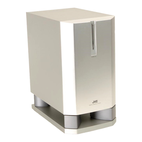
COMPACT COMPONENT SYSTEM
SP-DW103
Powered Subwoofer
Subwoofer motriz
Subwoofer energizado
INSTRUCTIONS
MANUAL DE INSTRUCCIONES
INSTRUÇÕES
For Customer Use:
Enter below the Model No. and Serial
No. which are located either on the rear,
bottom or side of the cabinet. Retain this
information for future reference.
Model No.
Serial No.
LVT1030-002C
[US/UJ/UW/UG]
SP-DW103[UW_UG]_F.p65 03.6.3, 6:23 PM1

English
Front view Side view
Thank you for purchasing a JVC speaker.
Before you begin using it, please read the instructions carefully
to be sure you get the best possible performance. If you have any
questions, consult your JVC dealer.
Warnings, Cautions and Others
To reduce the risk of electrical shocks, fire, etc.:
1. Do not remove screws, covers or cabinet.
2. Do not expose this appliance to rain or moisture.
Caution—POWER switch
This apparatus is provided with the POWER switch to minimize
power consumption for safe use. Therefore,
1. Before doing initial settings, complete all the connections
required, connect the mains plug into the wall outlet, then set
the POWER switch to ON [ ❙].
2. When not in use, set the POWER switch to OFF [ ‡].
This disconnects the mains line.
Cautions
• Do not block the ventilation openings or holes.
(If the ventilation openings or holes are blocked by a
newspaper or cloth, etc., the heat may not be able to get out.)
• Do not place any naked flame sources, such as lighted
candles, on the apparatus.
• When discarding batteries, environmental problems must be
considered and local rules or laws governing the disposal of
these batteries must be followed strictly.
• Do not expose this apparatus to rain, moisture, dripping or
splashing and that no objects filled with liquids, such as vases,
shall be placed on the apparatus.
Caution—Proper Ventilation
To avoid risk of electric shock and fire, and to prevent damage,
locate the apparatus as follows:
1 Front:
No obstructions and open spacing.
2 Sides/ Top/ Back:
No obstructions should be placed in the areas shown by the
dimensions below.
3 Bottom:
Place on the level surface. Maintain an adequate air path
for ventilation by placing on a stand with a height of 10 cm
or more.
Precautions for installation
• To prevent deformation or discoloration of the
cabinet, do not install the unit where it is exposed
to direct sunlight or high humidity, and avoid
installation near air conditioning outlets.
• Speaker vibrations may cause howling. Place the
unit as far away from the player as possible.
• Take the occurrence of earthquakes or other
physical shocks into consideration when selecting
the installation place, and secure the unit
thoroughly.
• This unit is magnetically shielded to avoid color distortions on
TVs. However, if not installed properly, it may cause color
distortions. So, pay attention to the following when installing
the unit.
– When placing this unit near a TV set, turn off the TV’s main
power switch or unplug it before installing this unit.
Then wait at least 30 minutes before turning on the TV’s
main power switch again.
Some TVs may still be affected even though you have followed
the above. If this happens, move this unit away from the TV.
• Tuner reception may become noisy or hissing if this unit is
installed nearby the tuner. In this case, leave a more distance
between the tuner and this unit or use an outdoor antenna for
better tuner reception without interference from this unit.
Precautions for Daily Use
• To maintain the appearance of the unit
Wipe with a dry, soft cloth if the cabinet or control panel should
become dirty.
If very dirty, apply a small amount of water or neutral detergent
to the cloth and wipe clean. Then wipe with a dry cloth.
• To improve the sound field
If the speakers are facing a solid wall or glass
door, etc., it is recommended to furnish the wall
with materials that absorb sounds, for example by
hanging up thick curtains, to prevent reflections
and standing waves.
Checking the Supplied Accessories
Check to be sure you have the following supplied accessories.
The number in parenthesis indicates the quantity of the piece
supplied.
•Monaural audio cord (1)
•AC plug adaptor (1)
If the item mentioned above is missing, contact your dealer
immediately.
Front
15 cm15 cm
20 cm
10 cm
20 cm
20 cm
– G–1 –
SP-DW103[US]_3.p65 03.3.7, 4:16 PM2

Español
15 cm15 cm
20 cm
10 cm
20 cm
20 cm
Vista delantera Vista lateral
Precauciones sobre la instalación
• Para evitar la deformación o la alteración de color
de la caja, no instale la unidad en un sitio
expuesto a la luz directa del sol o a la alta
humedad ni cerca de las bocas de salidas del
aire acondicionado.
• Las vibraciones del altavoz pueden producir
aullido. Coloque la unidad lo más lejos posible del
tocadiscos.
• Al decidir el sitio de instalación de la unidad,
tenga en cuenta las eventualidades tales como
los terremotos y otros golpes físicos y asegúrela
firmemente para evitar que se voltee.
• Esta unidad está blindada magnéticamente para evitar
distorsiones de color en los televisores. Sin embargo, si no
está correctamente instalada, se podrían producir distorsiones
de color. Por lo tanto, preste atención a lo siguiente cuando se
instale la unidad.
– Si va a instalar esta unidad cerca de un televisor,
desconecte el interruptor de alimentación principal del
televisor o desenchúfelo antes de instalar esta unidad.
Luego espere por lo menos 30 minutos antes de volver a
conectar el interruptor de alimentación principal del televiso.
Aunque siga las instrucciones de arriba, algunos televisores
podrían ser afectados. En tal caso, aleje esta unidad del
televisor.
• Si instalara esta unidad cerca del sintonizador, se podrían
producir ruidos o silbidos en la recepción del sintonizador. En
tal caso, deje una distancia mayor entre el sintonizador y esta
unidad, o utilice una antena exterior para mejorar la recepción,
y prevenir las interferencias de esta unidad.
Precauciones durante el uso diario
• Para mantener la apariencia de la unidad
Si se ensucia la caja o el panel de control, limpie con un paño
suave y seco.
Si está muy sucio, limpie con un paño humedecido con agua o
detergente neutro, y seque con un paño seco.
• Mejoramiento del campo acústico
Si los altavoces están dirigidos hacia una pared
maciza o una puerta de vidrio, etc., se
recomienda revestir la pared con materiales
amortiguadores de sonido, por ejemplo,
instalando cortinas pesadas, para evitar
reverberaciones y ondas estacionarias.
Comprobación de los accesorios suministrados
Compruebe que dispone del siguiente accesorio suministrado.
El número entre paréntesis indica la cantidad de piezas
suministradas.
•Cordón de audio monofónico (1)
•Adaptador para clavija de CA (1)
Si no se le ha suministrado el elemento mencionado arriba,
póngase inmediatamente en contacto con su concesionario.
Gracias por la compra de un altavoz JVC.
Para obtener el mejor rendimiento posible, por favor lea
atentamente las instrucciones antes de intentar el uso. Si
tienenaluna pregunta, acuda a su agente de JVC.
Advertencias, precauciones y notas
Para reducir el riesgo de incendios, descargas eléctricas, etc.:
1. No retire los tornillos, las cubiertas o la caja.
2. No exponga este aparato a la lluvia o la humedad.
Precaución—Interruptor POWER
Este aparato está provisto del interruptor POWER para reducir al
mínimo el consumo de electricidad y asegurar un uso seguro.
Por consiguinte,
1. Antes de realizar los ajustes iniciales, complete todas las
conexiones según se requiera, conecte el enchufe en el
tomacorriente mural, y luego ajuste el interruptor POWER a
ON [ ❙].
2. Cuando no esté en uso, ajuste el interruptor POWER a OFF [ ‡].
Con esto se desconectará la red principal.
Precaución
• No obstruya las rendijas o los orificios de ventilación.
(Si las rendijas o los orificios de ventilación quedan tapados
con un periódico, un trozo de tela, etc., no se podrá disipar el
calor).
• No ponga sobre el aparato ninguna llama al descubierto,
como velas encendidas.
• Cuando tenga que descartar las pilas, tenga en cuenta los
problemas ambientales y observe estrictamente los
reglamentos o las leyes locales sobre disposición de las pilas.
• No exponga este aparato a la lluvia, humedad, goteos o
salpicaduras. Tampoco ponga recipientes conteniendo
líquidos, como floreros, encima del aparato.
Precaución—Ventilación apropiada
Para evitar riesgos de incendios o de descargas eléctricas u
otros daños, coloque el aparato de la siguiente manera:
1 Parte delantera:
Sin obstrucciones y con espacio abierto.
2 Laterales/ parte superior/ parte trasera:
No debe haber ninguna obstrucción dentro de las áreas
indicadas por las dimensiones de abajo.
3 Parte inferior:
Debe instalarse sobre una superficie nivelada. Para una
ventilación adecuada, colóquelo sobre un soporte de 10 cm
o más de altura para permitir el paso de aire.
Parte delantera
– G–2 –
SP-DW103[US]_3.p65 03.3.7, 4:16 PM3

Português
15 cm15 cm
20 cm
10 cm
20 cm
20 cm
Vista frontal Vista laterais
Precauções para instalação
• Para evitar a deformação ou descoloração do
gabinete, não instale o aparelho em local onde
fique exposto à luz direta do sol ou a alta
umidade. Evite também fazer a instalação perto
de saídas de ar condicionado.
• As vibrações do alto-falante podem provocar
sons semelhantes a uivos. Coloque o aparelho o
mais afastado possível do player.
• Ao escolher o local de instalação, leve em
consideração a ocorrência de tremores de terra
ou outros choques físicos e proteja o aparelho
contra eles.
• Este aparelho possui proteção magnética para evitar
distorções de cor nas televisões. No entanto, se não estiver
instalado corretamente, poderá provocar distorções de cor.
Observe o seguinte ao instalar o aparelho.
– Ao colocar este aparelho próximo a uma televisão, desligue
o interruptor de energia principal da televisão ou
desconecte-o antes de instalar o aparelho.
Em seguida, aguarde pelo menos 30 minutos antes de ligar
novamente o interruptor de energia principal da televisão.
Algumas televisões poderão ser afetadas mesmo que você
siga as instruções acima. Se isso acontecer, afaste este
aparelho da televisão.
• Se este aparelho estiver instalado próximo ao sintonizador, a
recepção do sintonizador poderá apresentar ruídos ou
chiados. Neste caso, deixe uma distância maior entre o
sintonizador e o aparelho ou utilize uma antena externa para
obter melhor recepção do sintonizador, sem interferência
deste aparelho.
Precauções durante o Uso Diário
• Para manter a aparência do aparelho
Se o gabinete ou o painel de controle ficarem sujos, limpe-os
com um pano seco e macio.
Se estiverem muito sujos, aplique uma pequena quantidade
de água ou detergente neutro no pano e limpe-os. Em
seguida, limpe com um pano seco.
• Para melhorar o campo de som
Se os alto-falantes estiverem voltados para uma
parede ou porta de vidro, é recomendável revestir
a parede com materiais que absorvam sons,
como cortinas espessas, para evitar reflexões e
ondas imóveis.
Verificação dos Acessórios Fornecidos
Verifique se recebeu os seguintes acessórios fornecidos.
O número entre parênteses indica a quantidade do item fornecido.
•Cabo de áudio monaural (1)
•Adaptador de plugue de energia de CA (1)
Se o item acima mencionado estiver faltando, entre em contato
com o seu revendedor autorizado imediatamente.
Gratos pela aquisição do alto-falante JVC.
Antes de desfrutar este sistema, leia atentamente as instruções
que o acompanham, de modo a assegurar-se da obtenção do
melhor desempenho possível. Caso surjam dúvidas
concernentes a este sistema, consulte o seu agente JVC.
Advertências, precauções e outras notas
Para reduzir riscos de choques elétricos, incêndio, etc.:
1. Não remova parafusos e tampas ou desmonte a caixa.
2. Não exponha este aparelho à chuva nem à umidade.
Precaução—Interruptor POWER
Este aparelho possui um interruptor POWER para minimizar o
consumo de energia e permitir uma utilização segura. Portanto,
1. Antes de preparar as configurações iniciais, complete todas
as conexões necessárias, conecte o plugue de alimentação
na tomada de parede e ajuste o interruptor POWER para
ON [ ❙].
2. Quando não estiver em uso, ajuste o interruptor POWER para
OFF [ ‡].
Este procedimento desconecta a linha de alimentação.
Precauções
• Não obstrua as aberturas e orifícios de ventilação. (Se os
orifícios ou aberturas de ventilação estiverem obstruídos por
qualquer papel ou tecido, não haverá circulação do ar quente.)
• Não coloque nenhum objeto com chamas, como velas
acesas, sobre o aparelho.
• Ao descartar as baterias, leve em consideração os problemas
que possam ser causados ao meio ambiente e os
regulamentos e leis locais e governamentais sobre
recolhimento dessas baterias devem ser rigorosamente
seguidos.
• Não exponha este aparelho à chuva, umidade, pingos ou
esguichos de água, nem coloque em cima do mesmo
qualquer tipo de recipiente que contenha líquidos, como por
exemplo vasos.
Precaução—Ventilação adequada
Para evitar riscos de choques elétricos e incêndios, e prevenir
avarias, instale o aparelho como segue:
1 Parte frontal:
Sem obstruções e espaços abertos.
2 Partes laterais/ Tampa/ Posterior:
Nenhuma obstrução deverá ser colocada entre as áreas
cujas dimensões são indicadas abaixo.
3 Parte inferior:
Instale-o sobre uma superfície plana. Deverá ser mantido
espaço suficiente para a ventilação se este for instalado
numa posição que tenha uma altura de 10 cm ou mais.
Vista Frontal
– G–3 –
SP-DW103[US]_3.p65 03.3.7, 4:17 PM4
有關放置的注意事項
•為了防止揚聲器箱的變形和變色,放置時應避開直
射的陽光、潮濕的場所、冷暖器設備的附近等。
•揚聲器的振動會引起嘯叫聲,因此請盡可能遠離唱
機。
•請充分考慮放置場所並固定牢靠,以免因地震或沖
擊而翻倒。
•本機已被磁性蔽屏以免電視機的色彩失真。然而,若沒有妥當
安裝,它可能導致色彩失真。因此,安裝本機時請注意下列事
項。
—當放置本裝置于電視機附近時,在安裝本機之前請關閉電視
機的主電源開關或拔出插頭。
然后在至少 30 分鐘后才再度打開電視機的主電源。
某些電視機可能仍舊受到影響,雖然您已遵照上述事項。出現
此情況時,請將本機移離電視機。
•若本機被安裝在調諧器附近,調諧器接收可能變得噪雜或出現
嘯聲。遇此情況時,請在調諧器與本機之間預留更多的空間,
或用室外天線以獲取較佳的調諧器接收而不受本機干擾。
每日使用的防範措施
•保持本揚聲器的美觀
揚聲器或操作面板上如有污垢,請用干燥的軟布擦拭干淨。
污垢嚴重時,請在布上蘸少許水或中性洗滌劑進行擦拭,然后
揩干。
•改善聲場
若揚聲器面對堅固牆壁或玻璃門等,我們建議您安
裝可隔離音響的材料于牆上,例如掛上厚厚的窗帘
以防反射和電波。
檢查附帶附件
查看您是否有下列附帶附件。括弧裡的數字表示附帶附件總數。
•單聲道音頻電線 (1)
•交流電插頭轉接器 (1)
若上述的項目遺漏,請即刻通知經銷商。
感謝您惠購 JVC 揚聲器。
在開始使用之前,請您仔細閱讀本使用說明書,以確保您獲得揚
聲器的最佳性能。如有疑問,請與 JVC 代理銷售商連系。
警告、注意及其他
為了防止發生觸電、火災等事故:
1. 請勿拆卸螺絲、蓋子或機箱。
2. 勿使本設備淋雨或受潮。
注意—POWER(電源)開關
本設備帶有 POWER(電源)開關,可將耗電量降低到最低限度
以確保安全使用。因此,
1. 在進行初始設定之前,請先完成所需的各種連接,將電源插頭
插入牆上插座,再將 POWER(電源)開關設定為 ON [ ❙ ]
(開)。
2. 不用時請將 POWER(電源)開關設為 OFF [O](關)。
這將切斷主電線。
注意
•請勿堵塞通風口或通風孔。
(如果通風口或通風孔式被報紙或布等堵塞,熱量將無法散出。)
•請勿在本設備上放置任何裸露的火源,如點燃的蜡燭。
•處理廢棄電池時,必須考慮環境問題,並嚴格遵守當地關于處
理廢棄電池的有關法律或規定。
•請勿將本設備暴露于雨中,有水蒸氣的地方,可能落上或濺上
水滴的地方;亦請勿將裝滿液體的容器,如花瓶等放到本設備
的上面。
注意—正確通風
為了避免觸電和火災事故,同時也為了防止造成損害,請按下列
要求來放置設備:
1 前部:
應當開闊,無阻礙。
2 兩側∕頂部∕背部:
在下圖所示的尺寸范圍內不得放置任何障礙物。
3 底部:
應放在平面上。為了確保足夠的通風道,請放于高度在
10cm 以上的台架上。
前視圖 側視圖
15 cm15 cm
20 cm
10 cm
20 cm
20 cm
前面
- G–4 -
SP_DW103[US]_Chinese.p65 5/9/03, 1:42 PM21

WbI*«
–G–5–
WŽULÝ ¡«dý vKŽ «dJýJVCÆ
qJÐ ULOKF²« qOœ …¡«d vłd¹ ¨WŽUL « Ác¼ qLF²ÝUÐ ¡b³« q³
WUŠ w ÆWŽUL « Ác¼ s W¹œQð qC« vKŽ ‰uB(« qł« s W¹UMŽ
qOË WFł«d vłd¹ ¨«—U H²Ý« W¹« œułËJVCÆ
Èdš« ¡UOý«Ë UNO³MðË ¨«d¹c%Èdš« ¡UOý«Ë UNO³MðË ¨«d¹c%
Èdš« ¡UOý«Ë UNO³MðË ¨«d¹c%
M−²Ò∫Æa« ¨o¹d(« ¨WOzUÐdNJ« UbB« dDš V ƱÆW½«e)« Ë« WODžô« Ë« wž«d³« pHð ô Æ≤dFð ôÒÆWÐuÞd« Ë« dDLK “UN'« «c¼ ÷
WOzUÐdNJ« WUD« ÕU²H ≠ tO³Mð WOzUÐdNJ« WUD« ÕU²H ≠ tO³Mð
WOzUÐdNJ« WUD« ÕU²H ≠ tO³MðPOWER
Ëe WŽUL « Ác¼Ò WOzUÐdNJ« WUDK ÕU²H0 …œPOWERqOKI²
¨«cN ¨5ô« ‰ULF²Ýô« qł« s WOzUÐdNJ« WUD« „öN²Ý«
Ʊ¨WÐuKD*« öOu²« q qL« ¨WOËô« UÞu³C« qLŽ q³
…œułu*« WOzUÐdNJ« WUD« Wײ l w Ozd« fÐUI« qË«Ë
WOzUÐdNJ« WUD« ÕU²H l{ p– bFÐË ¨—«b'« wPOWERvKŽ qOGAð l{ËON [ ❙]ÆÆ≤ WOzUÐdNJ« WUD« ÕU²H l{ ¨‰ULF²Ýô« ÂbŽ WUŠ wPOWER ·UI¹« l{Ë vKŽOFF [ ‡]Æ
Æw Ozd« WOzUÐdNJ« WUD« jš WOKLF« Ác¼ qBHð
UNO³MðUNO³Mð
UNO³MðUNO³Mð
UNO³Mð
•Æ»uI¦« Ë« W¹uN²« Uײ oKGð ô
‚—Ë WDÝ«uÐ »uI¦« Ë« W¹uN²« Uײ ‚öž« WUŠ w®
©ÆÃ—UK …—«d(« Ãdð ô Ê« sJ1 t½U ¨a« ¨‘ULI« Ë« n×B« •vKŽ ¨W¾OC*« ŸuLA« q¦ ¨WuAJ W¹—«dŠ —œUB W¹« lCð ô
Æ“UN'« •—U³²Žô« 5FÐ WO¾O³« qUA cš« V−¹ ¨U¹—UD³« ·öð« bMŽ
OI²« V−¹ËÒÁc¼ ·öð« rJ% w²« 5½«uI« Ë« WOK;« WLE½ôUÐ b
ÆWIOœ …—uBÐ U¹—UD³« •dFð ôÒoý— Ë« ¨¡U*« jOIMð Ë« ¨WÐuÞd« Ë« ¨dDLK “UN'« «c¼ ÷
U¹d¼e q¦ qz«u « Ë« ¡U*UÐ …¡uK2 WOŽË« Í« lCð ôË ¡U*«
Æ“UN'« «c¼ vKŽ œ—u«
tO³MðtO³Mð
tO³MðtO³Mð
tO³Mð—
W×O×B« W¹uN²«W×O×B« W¹uN²«
W×O×B« W¹uN²« M−²Òl{ ¨—dC« lM*Ë ¨o¹d(«Ë WOzUÐdNJ« WÐdC« dÞU V
∫wK¹ UL “UN'«
±∫WbI*«
ÆÕu²H ⁄«d œułË l oz«uŽ ÊËbÐ ≤∫WOHK)«ØWLI«ØV½«u'«
œUFÐô« WDÝ«uÐ WMO³*« oÞUM*« w oz«uŽ Í« l{Ë ÂbŽ V−¹
ÆqHÝô« w ≥∫…bŽUI«
¡«u¼ Èd− œułË vKŽ kUŠ Æu² `DÝ vKŽ “UN'« l{
ŸUHð—UÐ qUŠ vKŽ “UN'« l{Ë WDÝ«uÐ W¹uN²« qł« s ·U
Æd¦« Ë« rÝ ±∞
wU« dEMwU« dEM
wU« dEMwU« dEM
wU« dEM
w³½Uł dEMw³½Uł dEM
w³½Uł dEMw³½Uł dEM
w³½Uł dEM
rÝ ≤∞
rÝ ≤∞
rÝ ≤∞
rÝ ±µ rÝ ±µ
rÝ ±∞
VOd²K WLN «d¹c%VOd²K WLN «d¹c%
VOd²K WLN «d¹c%
•OGðË t¹uAð lM*ÒWŽUL « Vdð ô ¨WMOÐUJ« Êu d
Ë« …dýU³*« fLA« WFýô W{dF sU« w
M&Ë WOUF« WÐuÞd«ÒWŽUL « VOdð pc V
Æ¡«uN« nOOJð ×U Uײ »dIÐ
•ÆwA¹uAð oOŽ“ WŽUL « “«e²¼« V³ ¹ Ê« sJ1
GA*« s …bOFÐ WU vKŽ WŽUL « l{Ò—bIÐ q ÆÊUJô«
•Èdšô« «“«e²¼ô«Ë WO{—ô« «eN« cš« V−¹
¨WŽUL « VOdð ÊUJ —UO²š« bMŽ —U³²Žô« 5FÐ
ÆWLJ× …—uBÐ WŽUL « XO³¦ð V−¹ «cNË
•Ê«uô —u¼bð V³ ð ô v²Š UO ODMG WËeF WŽUL « Ác¼
dOž …—uBÐ WŽUL « VOdð WUŠ w ¨p– lË ÆÊu¹eHK²«
—u¼bð `O×B« dOž VOd²« V³ ¹ Ê« sJ1 t½U ¨W×O×
ÆWŽUL « VOdð bMŽ wK¹ U* t³²½« ¨«cN ÆÊ«uö ≠WUD« ÕU²H qB« ¨Êu¹eHK²« »dIÐ WŽUL « Ác¼ l{Ë bMŽ
WOzUÐdNJ« WUD« pKÝ Ÿe½« Ë« Êu¹eHK²K w Ozd« WOzUÐdNJ«
ÆWŽUL « Ác¼ VOdð q³
WUD« ÕU²H qOuð q³ qô« vKŽ WIOœ ≥∞ dE²½« „«– bFÐ
ÆWO½UŁ …d Êu¹eHK²K WOzUÐdNJ«
¡«dłô« XF³ð« p½« lË …dŁQ² U½u¹eHK²« iFÐ vI³ð Ê« sJ1
Êu¹eHK²« sŽ WŽUL « Ác¼ bFЫ ¨p– qBŠ «–« ÆvKŽô« w —uc*«
ÆÊUJô« —bIÐ
•W N ¼ vKŽ Íu²×¹ Ë« UýuA n«u*« ‰U³I²Ý« `³B¹ Ê« sJ1
„dð« WU(« Ác¼ w Æn«u*« »dIÐ WŽUL « Ác¼ VOdð - «–«
wz«u¼ qLF²Ý« Ë« WŽUL « Ác¼Ë n«u*« 5Ð WOU WU
ÆWŽUL « Ác¼ s g¹uAð ÊËbÐ qC« ‰U³I²Ý« qł« s wł—Uš
wuO« ‰ULF²Ýö WLN «d¹c%wuO« ‰ULF²Ýö WLN «d¹c%
wuO« ‰ULF²Ýö WLN «d¹c%
•
WŽUL « dNE vKŽ WEU×LKWŽUL « dNE vKŽ WEU×LK
WŽUL « dNE vKŽ WEU×LK
WMOÐUJ« X׳« «–« WUłË WLŽU½ ‘UL WFDIÐ WŽUL « ` «
ÆWÝË rJײ« WŠu Ë«
EM Ë« ¡U*« s WKOK WOL l{ ¨«bł WÝË WŽUL « X½U «–«Òn nHł p– bFÐ ÆWŽUL « ` «Ë ‘ULI« WFD vKŽ ‰œUF²
ÆWUł ‘UL WFDIÐ WŽUL «
•
wðuB« ‰U:« 5 ײwðuB« ‰U:« 5 ײ
wðuB« ‰U:« 5 ײ
»UÐ Ë« VK —«b' WNł«u UŽUL « X½U «–«
¹ ¨Æa« ¨włUł“ÔÊ« sJ1 œ«u0 —«b'« WODG²Ð `BM
¨WJOLÝ dzU²Ý oOKFð WDÝ«uÐ ö¦ ¨«uô« h²9
ÆW¹œuLF« ëuô«Ë UÝUJF½ô« lM* p–Ë
WId*« UI×K*« h×WId*« UI×K*« h×
WId*« UI×K*« h×
ÆWOU²« WId*« UI×K*« œułË s bQð
O³¹ÒÆWId*« lDI« WOL ”«uô« 5Ð œułu*« rd« s
•
©±® ÍœUŠ« u pKÝ©±® ÍœUŠ« u pKÝ
©±® ÍœUŠ« u pKÝ
•
WOzUÐdNJ« WUD« fÐU T¹UN WOzUÐdNJ« WUD« fÐU T¹UN
WOzUÐdNJ« WUD« fÐU T¹UNAC
©±® ©±®
©±® ©±®
©±®
Æ«—u pKOLŽ dA²Ý« ¨«œuIH vKŽô« w —uc*« bM³« ÊU «–«
SP-DW103(AR)_p65 6/3/03, 3:14 PM5

English
Português Español
1
1
1
3
5
Contenido
Índice
The printed pattern of the rear panel may differs according to the countries of purchase.
El panel impreso en el panel trasero puede diferir según el país de compra.
A etiqueta impressa no painel traseiro poderá ser diferente dependendo do país em que
o equipamento for adquirido.
English
Español
Português
Conexiones ..................................................................................... 1
Verificación de su amplificador ......................................................... 1
Conexión al amplificador .................................................................. 1
Operaciones.................................................................................... 3
Información adicional .................................................................... 5
Conexões ........................................................................................ 1
Para Verificar o Amplificador ............................................................ 1
Para Conectar ao Amplificador ........................................................ 1
Operações ....................................................................................... 3
Informações Adicionais ................................................................. 5
Connections.................................................................................... 1
Checking Your Amplifier .................................................................... 1
Connecting to the Amplifier .............................................................. 1
Operations ...................................................................................... 3
Additional Infromation ................................................................... 5
Contents
SP-DW103[US]_3.p65 03.3.7, 4:17 PM7

English
Checking Your Amplifier
Before connecting this unit to your amplifier (or receiver), check
what types of connecting terminals your amplifier has.
Follow the instructions below to find a proper connection method
for your equipment.
• Illustrations of jacks and terminals in this manual may be
different from the ones actually used for your amplifier. The
illustrations are of the most used type.
First check whether your amplifier has a subwoofer output
jack.
It is usually named and printed as the “SUBWOOFER OUT” or
“SUBWOOFER.”
If you find it on your amplifier, follow Connecting Method Å.
Next check whether your amplifier has line output jacks.
They are usually named and printed as “LINE OUT” or “LINE
OUTPUT.”
If you find them on your amplifier, follow Connecting Method ı.
Follow Connecting Method Ç.
This connection can be used for any amplifier, by connecting the
front speaker terminals of the amplifier (usually named and
printed as “FRONT SPEAKERS” or “MAIN SPEAKERS”).
Connections
SUBWOOFER
OUT
LINE OUT
L
R
RIGHT LEFT
FRONT SPEAKERS
2
1
Main (Front) Speakers
(not supplied)
Your Amplifier
SP-DW103
Monaural audio cord
(supplied)
Before connecting this unit to the amplifier (or receiver),
observe the following carefully.
• Before connecting this unit to an amplifier, turn off the
amplifier first.
• Make all connections before plugging in this unit.
• DO NOT use the INPUT 1 (LOW-LEVEL) and INPUT 2
(HIGH-LEVEL) terminals on the rear of this unit at the
same time; otherwise, noise will be heard and may
damage the unit.
• DO NOT connect this unit to the REC OUT jacks of your
amplifier.
Connecting to the Amplifier
When connecting to your amplifier (or receiver), refer also the
manual supplied for your equipment.
Connecting Method Å
Connect an amplifier having a subwoofer output jack to the
LEFT/MONO jack of the INPUT 1 (LOW-LEVEL) terminal.
Preparation:
Use the supplied monaural
audio cord.
To an AC outlet
SUBWOOFER
OUT
RIGHT LEFT/MONO
(LOW-LEVEL)
INPUT 1
TO MAIN
SPEAKERS
RIGHT
RIGHT LEFT
RIGHT LEFT
LEFT/MONO
MAX
VOLUME
50Hz
200Hz
MIN
ONOFF
FIXED
VARIABLE
POWER
FREQUENCY
CUT OFF FILTER
INPUT 2
(HIGH-LEVEL)
(LOW-LEVEL)
INPUT 1
AUTO POWER ON/STANDBY
PHASE
CANCEL
ON
REVERSE
NORMAL
When using Connecting Method Å, no signal comes out of
the TO MAIN SPEAKERS terminal.
If you cannot
find any
If you cannot
find any
– 1 –
SP-DW103[US]_3.p65 03.3.7, 4:17 PM8

English
How to connect the speaker cords:
1Press and hold the clamp of the speaker terminal.
2Insert the end of the speaker cord into the terminal as
illustrated below.
• Match the polarity of the speaker terminals: ªto ªand ·
to ·.
3Release the finger from the clamp.
• When you connect main (front) speakers to the TO MAIN
SPEAKERS terminal, use the speakers within the
impedance range indicated by the amplifier connected to
the INPUT 2 (HIGH-LEVEL) terminal. If not, the amplifier
connected to the INPUT 2 (HIGH-LEVEL) terminal may
malfunction and be damaged.
• DO NOT connect more than one speaker to one speaker
terminal.
TO MAIN
SPEAKERS
RIGHT
RIGHT LEFT
RIGHT LEFT
LEFT/MONO
MAX
VOLUME
50Hz
200Hz
MIN
ONOFF
FIXED
VARIABLE
POWER
FREQUENCY
CUT OFF FILTER
RIGHT LEFT
FRONT SPEAKERS
TO MAIN
SPEAKERS
INPUT 2
(HIGH-LEVEL)
RIGHT LEFT
RIGHT LEFT
INPUT 2
(HIGH-LEVEL)
(LOW-LEVEL)
INPUT 1
AUTO POWER ON/STANDBY
PHASE
CANCEL
ON
REVERSE
NORMAL
2
1
Connecting Method ı
Connect an amplifier having line output jacks to the INPUT 1
(LOW-LEVEL) terminal.
Preparation:
Purchase a stereo audio cord at
an audio shop or electric shop.
If your amplifier has only a monaural line output (MONO)
jack, connect it to the LEFT/MONO jack of the INPUT 1
(LOW-LEVEL) terminal (see Connecting Method Å).
TO MAIN
SPEAKERS
RIGHT
RIGHT LEFT
RIGHT LEFT
LEFT/MONO
MAX
VOLUME
50Hz
200Hz
MIN
ONOFF
FIXED
VARIABLE
POWER
FREQUENCY
CUT OFF FILTER
LINE OUT
L
R
RIGHT LEFT/MONO
(LOW-LEVEL)
INPUT 1
INPUT 2
(HIGH-LEVEL)
(LOW-LEVEL)
INPUT 1
AUTO POWER ON/STANDBY
PHASE
CANCEL
ON
REVERSE
NORMAL
Main (Front) Speakers
(not supplied)
Your Amplifier
SP-DW103
Your Amplifier
SP-DW103
Main (Front) Speakers
(not supplied)
Speaker cords
(not supplied)
Stereo audio cord
(not supplied)
To an AC outlet
To an AC
outlet
Right speaker Left speaker
Connecting Method Ç
Connect an amplifier without a subwoofer output jack and line
output jacks to the INPUT 2 (HIGH-LEVEL) terminal.
• When this method is used, connect your main (front) speakers
to the TO MAIN SPEAKERS terminal on the rear of this unit.
Preparation:
Purchase speaker cords at an
audio shop or electric shop.
Speaker cords
(not supplied)
123
– 2 –
SP-DW103[US]_3.p65 03.3.7, 4:17 PM9

English
The unit automatically accommodates AC power between
110V and 240V. You do not need any setting to match the
unit with your local power voltage.
Turning On the Power—POWER Å
Press the ON [ ❙] portion of the POWER switch.
The main power turns on and the power lamp in the front panel
lights in green.
• The power lamp lights in red when the Auto Power On/
Standby places the unit into standby mode (see page 4).
To completely cut off the power to this unit
Press the OFF [ ‡] portion of the POWER switch.
This will disconnect the mains lead.
Adjusting the Volume—VOLUME ı
Adjust the volume output level through this unit while comparing
with the sounds coming out of the main (front) speakers.
• Once you have adjusted the volume output level of this unit,
you do not need to adjust it each time you use this unit.
Adjusting the volume level on the connected amplifier will also
adjust the volume level through this unit.
1Turn the VOLUME knob to the MIN position.
2Turn on the connected amplifier and start playing a
source.
Playback sounds come out of the main (front) speakers and
this unit.
3Adjust the VOLUME knob to obtain a well-balanced sound
level with that of the main (front) speakers.
If the volume is set at a high level before starting play, the
sudden blast of sound energy can permanently damage
your hearing and/or ruin your speakers.
Operations
MAX
VOLUME
MIN
MAX
VOLUME
MIN
Power
lamp
Front view
Rear view
TO MAIN
INPUT 2
(HIGH-LEVEL)
(LOW-LEVEL)
RIGHT
RIGHT LEFT
RIGHT LEFT
LEFT/MONO
MAX
VOLUME
50Hz
200Hz
MIN
CANCEL
ON
ONOFF
REVERSE
NORMAL
FIXED
VARIABLE
INPUT 1
POWER
FREQUENCY
AUTO POWER ON/STANDBY
PHASE CUT OFF FILTER
Å
Ç
ıÇ
Î
‰
POWER
PHASE
AUTO POWER
ON/STANDBY
VOLUME FREQUENCY
CUT OFF
FILTER
SPEAKERS
– 3 –
SP-DW103[US]_3.p65 03.3.7, 4:17 PM10

English
Changing the Phase—PHASE Î
You can change the sound phase to match your preference.
Select either “NORMAL” or “REVERSE” to obtain a better bass
sound.
Press in or out the PHASE button to select either the
NORMAL position or the REVERSE position.
• NORMAL : Normally select this.
• REVERSE: Select this when you feel the bass sound is better
with this mode rather than with “NORMAL.”
Operating the Unit Automatically According to the
Incoming Signals—AUTO POWER ON/STANDBY ‰
By using this function, this unit automatically enters standby
mode even though the POWER switch is turned ON [ ❙].
Press the AUTO POWER ON/STANDBY button to the —ON
position.
• If no sound comes in for about 10 minutes, the unit
automatically enters standby mode. The power lamp lights in
red. Then if the unit detects incoming signals, this unit starts
operating automatically (the power lamp now lights in green).
If Auto Power On/Standby does not work correctly (see
“MEMO” below), press out the AUTO POWER ON/STANDBY
button to set it to the _CANCEL position. Auto Power On/
Standby is canceled.
When the volume level of the amplifier is so low or the
incoming signals are so weak that this unit cannot detect
sounds, Auto Power On/Standby may not work correctly.
• This unit may enter standby mode even though signals
are coming in.
• This unit may not start operating after entering standby
mode, even though signals start coming in.
Adjusting the Crossover Frequency
—CUT OFF FILTER and FREQUENCY Ç
You can adjust the crossover frequency to determine the bass
sound level this unit handles.
• Once it is set, only the sounds below the frequency come out
of the built-in speaker.
When the main speakers in use are JVC’s SP-X103,
SP-F303 or SX-XD33
Press in the CUT OFF FILTER button to set it to the _FIX
position.
• The FREQUENCY knob is deactivated.
• When your amplifier is equipped with crossover frequency
setting, set it within the range of 100 Hz to 150 Hz.
• When your amplifier is equipped with speaker size setting,
select “small.”
If your amplifier is not provided with a crossover
frequency setting:
1Press out the CUT OFF FILTER button to set it to the —
VARIABLE position.
Now the FREQUENCY knob is activated and you can adjust
the crossover frequency on this unit.
2Turn the FREQUENCY knob to obtain the best matching
crossover frequency with your main speakers.
Adjust the frequency (50 Hz to 200 Hz) while listening to
playback sound coming out of both the main speakers and this
unit.
• If your main speakers can reproduce the bass sound well,
adjust the frequency at a lower level.
• If you feel bass sounds are not sufficient, adjust the
frequency at a higher level.
200Hz
FREQUENCY
50Hz
FIX
VARIABLE
CUT OFF FILTER
REVERSE
NORMAL
PHASE
CANCEL
ON
AUTO POWER ON / STANDBY
CANCEL
ON
AUTO POWER ON / STANDBY
FIX
VARIABLE
CUT OFF FILTER
– 4 –
SP-DW103[US]_3.p65 03.3.7, 4:17 PM11

English
Specifications
Type : Powered Subwoofer
Bass-reflex type, (magnetically shielded type)
Speaker unit : 16.0 cm cone (× 1)
Frequency range : 30 Hz to 200 Hz
Input impedance : 50 kΩ(LOW-LEVEL)
470 Ω(HIGH-LEVEL)
Input terminals : INPUT 1 (LOW-LEVEL)
INPUT 2 (HIGH-LEVEL)
Power requirements : AC 110 V–240 V , 50 Hz/60 Hz
Output power of built-in amp : 100 W (45 Hz, 4 Ω, 10 % THD)
Power consumption : 27 W
Dimensions : 210 mm (width) ×392 mm (height) ×348 mm (depth)
Mass : 10 kg
Accessories : Monaural audio cord (× 1)
AC plug adaptor (× 1)
Speaker layout
To obtain the best possible sound from your unit:
—Place a subwoofer wherever you like since bass sound is non-
directional. Normally place it in front of you.
—Place all the main speakers at the same distance from the
listening position.
Additional Information
Subwoofer
Left front
speaker
Right front
speaker
Center
speaker
Listening position
Left surround
speaker
Right surround
speaker
Troubleshooting
Use this chart to help you solve daily operational problems. If there is any problem you cannot solve, contact your dealer.
Possible Cause
Is the unit pugged in?
Signals are too weak or volume level is
too low.
Is the VOLUME knob turned to the MIN
position?
Connections are incorrect, or loose.
Audio signals through the amplifier are
extremely weak.
The built-in protective circuit is working.
The VOLUME knob on the rear is set to
a very high level.
The volume of the playback source is too
high.
Symptom
Power does not come on.
Auto Power On/Standby does not function
correctly.
No sound is heard.
Sounds fluctuate (suddenly become loud
or soft).
Suddenly no sound comes out.
—the power lamp lights in red.
Suddenly no sound comes out.
—the power lamp still lights in green.
Action
Plug the AC power cord firmly into the AC
outlet.
This is not a malfunction. If this happens,
cancel Auto Power On/Standby.
Turn the VOLUME knob until a suitable volume
is found.
Check the connections. If incorrect, redo the
corrections. (See pages 1 and 2.)
Increase the volume level on the amplifier.
Lower the volume level on the amplifier so that
the symptom will not occur.
Turn down the volume, then turn off and on
this unit.
Turn down the volume of the playback source,
turn off and on the source, then adjust the
volume properly on the source.
–5–
SP-DW103[US]_3.p65 03.3.7, 4:17 PM12

SP-DW103_SP_PR_3.p65 03.3.7, 3:56 PM13

Español
Conexiones
SUBWOOFER
OUT
LINE OUT
L
R
RIGHT LEFT
FRONT SPEAKERS
2
1
Su amplificador
SP-DW103
Cordón de audio
monofónico
(suministrado)
Antes de conectar esta unidad al amplificador (o receptor),
observe atentamente lo siguiente.
• Antes de conectar esta unidad a un amplificador, primero
apague el amplificador.
• Realice todas las conexiones antes de enchufar esta
unidad.
• NO utilice simultáneamente los terminales INPUT 1
(LOW-LEVEL) e INPUT 2 (HIGH-LEVEL) de la parte
trasera de esta unidad; de lo contrario, se podrían
escuchar ruidos o se dañaría la unidad.
• NO conecte esta unidad a los jacks REC OUT de su
amplificador.
Conexión al amplificador
Cuando efectúe la conexión al amplificador (o receptor),
refiérase también al manual suministrado para su equipo.
Método de conexión Å
Conecte un amplificador con jack de salida de subwoofer al jack
LEFT/MONO del terminal INPUT 1 (LOW-LEVEL).
Preparativo:
Utilice el cordón de audio
monofónico suministrado.
A una toma de CA
SUBWOOFER
OUT
RIGHT LEFT/MONO
(LOW-LEVEL)
INPUT 1
TO MAIN
SPEAKERS
RIGHT
RIGHT LEFT
RIGHT LEFT
LEFT/MONO
MAX
VOLUME
50Hz
200Hz
MIN
ONOFF
FIXED
VARIABLE
POWER
FREQUENCY
CUT OFF FILTER
INPUT 2
(HIGH-LEVEL)
(LOW-LEVEL)
INPUT 1
AUTO POWER ON/STANDBY
PHASE
CANCEL
ON
REVERSE
NORMAL
Verificación de su amplificador
Antes de conectar esta unidad a su amplificador (o receptor),
verifique cuáles son los tipos de terminales de conexión
provistos en su amplificador.
Siga las instrucciones de abajo para encontrar el método de
conexión apropiado para su equipo.
• En este manual, las ilustraciones de los jacks y terminales
pueden ser diferentes de los que se utilizan en su
amplificador. Las ilustraciones son las de uso más común.
Primero vea si su amplificador está provisto del jack de
salida de subwoofer.
Por lo general se provee la inscripción “SUBWOOFER OUT” o
“SUBWOOFER”.
Si su amplificador está provisto de tal inscripción, siga el
método de conexión Å.
Seguidamente vea si su amplificador está provisto de los
jacks de salida de línea.
Por lo general se provee la inscripción “LINE OUT”o“LINE OUTPUT”.
Si su amplificador está provisto de tal inscripción, siga el
método de conexión ı.
Siga el método de conexión Ç.
Esta conexión se puede usar para cualquier amplificador,
conectando los terminales para el altavoz delantero del
amplificador (por lo general llevan la inscripción “FRONT
SPEAKERS” o “MAIN SPEAKERS”).
Cuando utilice el método de conexión Å, la señal no será
generada desde el terminal TO MAIN SPEAKERS.
Si no existe tal
inscripción
Si no existe tal
inscripción
Altavoces principales
(delanteros)
(no suministrados)
– 1 –
SP-DW103_SP_PR_3.p65 03.3.7, 3:57 PM14

Español
Cómo conectar los cordones de altavoz:
1Presione y mantenga presionada la abrazadera del terminal
de altavoz.
2Inserte el extremo del cordón para altavoz en el terminal, tal
como se indica en la ilustración de abajo.
• Haga coincidir la polaridad de los terminales de altavoz:
ªcon ªy ·con ·.
3Suelte el dedo de la abrazadera.
• Cuando se conectan los altavoces principales
(delanteros) al terminal TO MAIN SPEAKERS, utilice
altavoces con el mismo margen de impedancia que el
indicado por el amplificador conectado al terminal
INPUT 2 (HIGH-LEVEL). De lo contrario, el amplificador
conectado al terminal INPUT 2 (HIGH-LEVEL) podría
funcionar defectuosamente y dañarse.
• NO conecte más de un altavoz a cada terminal de altavoz.
Método de conexión ı
Conecte un amplificador provisto de los jacks de salida de línea
al terminal INPUT 1 (LOW-LEVEL).
Preparativo:
Compre un cordón de audio
estéreo en un taller de audio o
un establecimiento del ramo.
Si su amplificador está provisto solamente del jack de
salida de línea monofónica (MONO), conéctelo al jack
LEFT/MONO del terminal INPUT 1 (LOW-LEVEL) (véase
método de conexión Å).
TO MAIN
SPEAKERS
RIGHT
RIGHT LEFT
RIGHT LEFT
LEFT/MONO
MAX
VOLUME
50Hz
200Hz
MIN
ONOFF
FIXED
VARIABLE
POWER
FREQUENCY
CUT OFF FILTER
LINE OUT
L
R
RIGHT LEFT/MONO
(LOW-LEVEL)
INPUT 1
INPUT 2
(HIGH-LEVEL)
(LOW-LEVEL)
INPUT 1
AUTO POWER ON/STANDBY
PHASE
CANCEL
ON
REVERSE
NORMAL
SP-DW103
SP-DW103
Altavoces principales
(delanteros)
(no suministrados)
A una toma de CA
Cordón de audio
estéreo
(no suministrado)
A una toma
de CA
Método de conexión Ç
Conecte un amplificador sin jack de salida de subwoofer ni jacks
de salida de línea al terminal INPUT 2 (HIGH-LEVEL).
• Cuando se utiliza este método, conecte los altavoces
principales (delanteros) al terminal TO MAIN SPEAKERS de
la parte trasera de esta unidad.
Preparativo:
Compre los cordones para
altavoz en un taller de audio o
un establecimiento del ramo.
TO MAIN
SPEAKERS
RIGHT
RIGHT LEFT
RIGHT LEFT
LEFT/MONO
MAX
VOLUME
50Hz
200Hz
MIN
ONOFF
FIXED
VARIABLE
POWER
FREQUENCY
CUT OFF FILTER
RIGHT LEFT
FRONT SPEAKERS
TO MAIN
SPEAKERS
INPUT 2
(HIGH-LEVEL)
RIGHT LEFT
RIGHT LEFT
INPUT 2
(HIGH-LEVEL)
(LOW-LEVEL)
INPUT 1
AUTO POWER ON/STANDBY
PHASE
CANCEL
ON
REVERSE
NORMAL
2
1
123
Altavoces principales
(delanteros)
(no suministrados)
Su amplificador
Su amplificador
Cordones para altavoz
(no suministrados)
Altavoz derecho Altavoz izquierdo
Cordones para altavoz
(no suministrados)
– 2 –
SP-DW103_SP_PR_3.p65 03.3.7, 3:57 PM15

Español
Conexión de la alimentación—POWER Å
Presione la parte ON [ ❙] del interruptor POWER.
El interruptor principal se conecta y la lámpara de alimentación
del panel frontal se enciende en verde.
• La lámpara de alimentación se enciende en rojo cuando la
unidad entra al modo de espera mediante Auto Power On/
Standby (véase página 4).
Para desconectar completamente la alimentación de esta
unidad
Pulse la parte OFF [ ‡] del interruptor POWER.
La unidad quedará desconectada de la red principal.
Ajuste del volumen—VOLUME ı
Ajuste el nivel de salida de volumen de esta unidad mientras
compara con los sonidos que salen de los altavoces principales
(delanteros).
• Una vez que se ajuste el nivel de salida de volumen de esta
unidad, no necesitará ajustarlo cada vez que utilice esta unidad.
Al ajustar el nivel de volumen del amplificador conectado
también se ajustará el nivel de volumen de esta unidad.
1Gire la perilla VOLUME hasta la posición MIN.
2Encienda el amplificador conectado y comience a
reproducir una fuente.
Los sonidos reproducidos salen de los altavoces principales
(delanteros) y esta unidad.
3Ajuste la perilla VOLUME para obtener un nivel de sonido
correctamente equilibrado con el de los altavoces
principales (delanteros).
Si se ajusta el volumen a un nivel alto antes de iniciar la
reproducción, el repentino estallido de energía acústica
podría dañar permanentemente su oído y/o arruinar sus
altavoces.
Operaciones
MAX
VOLUME
MIN
MAX
VOLUME
MIN
Lámpara de
alimentación
Vista delantera
Vista trasera
TO MAIN
INPUT 2
(HIGH-LEVEL)
(LOW-LEVEL)
RIGHT
RIGHT LEFT
RIGHT LEFT
LEFT/MONO
MAX
VOLUME
50Hz
200Hz
MIN
CANCEL
ON
ONOFF
REVERSE
NORMAL
FIXED
VARIABLE
INPUT 1
POWER
FREQUENCY
AUTO POWER ON/STANDBY
PHASE CUT OFF FILTER
Å
Ç
ıÇ
Î
‰
POWER
PHASE
AUTO POWER
ON/STANDBY
VOLUME FREQUENCY
CUT OFF
FILTER
SPEAKERS
La unidad se ajusta automáticamente a una alimentación
de CA de 110 V a 240 V. No es necesario realizar ajustes
para adaptar la unidad a la tensión de su localidad.
– 3 –
SP-DW103_SP_PR_3.p65 03.3.7, 3:57 PM16

Español
200Hz
FREQUENCY
50Hz
FIX
VARIABLE
CUT OFF FILTER
REVERSE
NORMAL
PHASE
Cambio de la fase—PHASE Î
La fase del sonido se puede cambiar según sus preferencias.
Seleccione “NORMAL” o “REVERSE” para obtener sonidos
graves mejores.
Pulse el botón PHASE para introducirlo o extraerlo a fin de
seleccionar la posición NORMAL o la posición REVERSE.
• NORMAL : Normalmente seleccione esta opción.
• REVERSE: Selecciónelo cuando sienta que los graves son
mejores que con “NORMAL”.
Funcionamiento automático de la unidad de acuerdo con
las señales entrantes—AUTO POWER ON/STANDBY ‰
Utilizando esta función, la unidad accederá automáticamente
al modo de espera aunque se ponga el interruptor POWER en
ON [ ❙].
Pulse el botón AUTO POWER ON/STANDBY y ajústelo a la
posición —ON.
• Si no entra ninguna señal durante aproximadamente
10 minutos, la unidad accede automáticamente al modo de
espera. La lámpara de alimentación se enciende en rojo.
Posteriormente, cuando la unidad detecta que hay señales
entrantes, la operación se iniciará automáticamente (la
lámpara de alimentación se enciende ahora en verde).
Si el encendido/espera automático no funciona
correctamente (véase “MEMO” más abajo), pulse el botón
AUTO POWER ON/STANDBY para ajustarlo a la posición
_CANCEL. El encendido/espera automático se cancela.
Cuando el nivel de volumen del amplificador es muy bajo o
las señales entrantes son tan débiles que la unidad no
puede detectar los sonidos, es posible que el encendido/
espera automático no funcione correctamente.
• Esta unidad puede entrar al modo de espera aunque
hayan señales entrantes.
• Puede suceder que esta unidad no empiece a funcionar
después de entrar al modo de espera, aunque hayan
señales entrantes.
CANCEL
ON
AUTO POWER ON / STANDBY
CANCEL
ON
AUTO POWER ON / STANDBY
FIX
VARIABLE
CUT OFF FILTER
Ajuste de la frecuencia de cruce
—CUT OFF FILTER y FREQUENCY Ç
Es posible ajustar la frecuencia de cruce para determinar el nivel
de los sonidos graves manejados por esta unidad.
• Una vez ajustada la frecuencia, el altavoz incorporado
generará solamente los sonidos que se encuentren por
debajo de la misma.
Cuando los altavoces principales utilizados sean
SP-X103, SP-F303 o SX-XD33 de JVC
Presione el botón CUT OFF FILTER para ajustarlo a la posición
_FIX.
• La perilla FREQUENCY está desactivada.
• Si su amplificador dispone del ajuste de la frecuencia de
cruce, ajústelo dentro del margen de 100 Hz a 150 Hz.
• Si su amplificador dispone del ajuste del tamaño de altavoz,
seleccione “small” (pequeño).
Si su amplificador no dispone del ajuste de la
frecuencia de cruce:
1Pulse el botón CUT OFF FILTER para ajustarlo a la
posición —VARIABLE.
Ahora, la perilla FREQUENCY se activa para que pueda
ajustar la frecuencia de cruce de esta unidad.
2Gire la perilla FREQUENCY hasta obtener la mejor
frecuencia de cruce para sus altavoces principales.
Ajuste la frecuencia (50 Hz a 200 Hz) mientras escucha el
sonido de reproducción que sale de los altavoces principales
y esta unidad.
• Si sus altavoces principales pueden reproducir también los
sonidos graves, ajuste la frecuencia a un nivel inferior.
• Si le parece que los sonidos graves no son suficientes,
ajuste la frecuencia a un nivel superior.
– 4 –
SP-DW103_SP_PR_3.p65 03.3.7, 3:57 PM17

Español
Disposición de los altavoces
Para obtener el mejor sonido posible de su unidad:
—Coloque un subwoofer en cualquier lugar deseado dado que
los sonidos graves son no direccionales. Normalmente
instálelo delante de usted.
—Coloque los altavoces principales a la misma distancia desde
la posición de audición.
Información adicional
Subwoofer
Altavoz
delantero
izquierdo
Altavoz
delantero
derecho
Altavoz
central
Posición de audición
Altavoz surround
izquierdo
Altavoz surround
derecho
Especificaciones
Tipo : Subwoofer motriz
Tipo bass-reflex (tipo blindado magnéticamente)
Unidad de altavoz : Cono de 16,0 cm (× 1)
Gama de frecuencias : 30 Hz a 200 Hz
Impedancia de entrada : 50 kΩ(LOW-LEVEL)
470 Ω(HIGH-LEVEL)
Terminales de entrada : INPUT 1 (LOW-LEVEL)
INPUT 2 (HIGH-LEVEL)
Requerimientos de potencia : AC 110 V–240 V , 50 Hz/60 Hz
Potencia de salida del amplificador inc. : 100 W (45 Hz, 4 Ω, 10 % THD)
Consumo : 27 W
Dimensiones : 210 mm (ancho) ×392 mm (alto) ×348 mm (fondo)
Peso : 10 kg
Accessorios : Cordón de audio monofónico (× 1)
Adaptador para clavija de CA (× 1)
Causa posible
¿Estála unidad enchufada?
Señales muy débiles o nivel de volumen
demasiado bajo.
¿Estála perilla VOLUME ajustada a la
posición MIN?
Conexiones incorrectas, o flojas.
Las señales de audio que salen del
amplificador son extremadamente débiles.
Se ha activado el circuito de protección
incorporado.
La perilla VOLUME de la parte trasera está
ajustada a un nivel muy alto.
El volumen de la fuente de reproducción es
demasiado alto.
Síntoma
La unidad no se encienda.
El encendido/espera automático no
funciona correctamente.
No se escucha sonido.
El sonido fluctúa (se vuelve
repentinamente alto o bajo).
El sonido se interrumpe súbitamente.
- la lámpara de alimentación se enciende
en rojo.
El sonido se interrumpe súbitamente.
- la lámpara de alimentación se enciende
en verde.
Acción
Enchufe firmemente el cable de
alimentación de CA en la toma de CA.
Esto no es una anomalía. En este caso,
cancele el encendido/espera automático.
Gire la perilla VOLUME hasta un volumen
apropiado.
Verifique las conexiones. Si están
incorrectas, vuelva a efectuar la conexión.
(Véase páginas 1 y 2).
Aumente el nivel de volumen en el
amplificador.
Baje el nivel de volumen en el amplificador
hasta eliminar el síntoma.
Baje el volumen y luego apague y vuelva a
encender esta unidad.
Baje el volumen de la fuente de
reproducción, apague y vuelva a encender
la fuente, y luego ajuste correctamente el
volumen de la fuente.
Localización y solución de problemas
Este cuadro le ayudaráa resolver los problemas operacionales diarios. Si hay algún problema que no puede resolver, póngase en
contacto con su concesionario.
–5 –
SP-DW103_SP_PR_3.p65 03.3.7, 3:57 PM18

SP-DW103_SP_PR_3.p65 03.3.7, 3:57 PM19

Português
Para Verificar o Amplificador
Antes de conectar este aparelho ao amplificador (ou receptor),
verifique os tipos de terminais de conexão existentes no
amplificador.
Siga as instruções a seguir para identificar o melhor método de
conexão para o seu equipamento.
•As ilustrações de tomadas e terminais apresentadas neste
manual podem ser diferentes daquelas realmente utilizadas
em seu amplificador. Elas representam o tipo mais utilizado.
Em primeiro lugar, verifique se o amplificador possui uma
tomada de saída do subwoofer.
Geralmente ela estáindicada como “SUBWOOFER OUT”ou
“SUBWOOFER”.
Se ela existir no amplificador, utilize o Método de ConexãoÅ.
Verifique se o amplificador possui tomadas de saída de linha.
Geralmente elas estão indicadas como “LINE OUT”ou “LINE
OUTPUT”.
Se elas existirem no amplificador, utilize o Método de
Conexãoı.
Utilize o Método de Conexão Ç.
Este tipo de conexão pode ser utilizado em qualquer
amplificador ligando-se os terminais do alto-falante dianteiro do
amplificador (geralmente indicados como “FRONT SPEAKERS”
ou “MAIN SPEAKERS”).
Conexões
SUBWOOFER
OUT
LINE OUT
L
R
RIGHT LEFT
FRONT SPEAKERS
2
1
Amplificador
Auto-falantes
Principais (Dianteiros)
(não fornecidos)
SP-DW103
Cabo de áudio
monaural (fornecido)
Se vocênão encontrar
nenhuma tomada
deste tipo
Antes de conectar este aparelho ao amplificador (ou
receptor), observe cuidadosamente o seguinte:
•Antes de conectar este aparelho a um amplificador,
primeiramente desligue o amplificador.
•Estabeleça todas as conexões antes de ligar este
aparelho.
•NÃO utilize simultaneamente os terminais INPUT 1
(LOW-LEVEL) e INPUT 2 (HIGH-LEVEL) localizados na
parte traseira deste aparelho; caso contrário, serão
emitidos ruídos e o aparelho poderáser danificado.
•NÃO conecte este aparelho às tomadas REC OUT do
amplificador.
Para Conectar ao Amplificador
Ao estabelecer a conexão com o amplificador (ou receptor),
consulte também o manual fornecido com o equipamento.
Método de Conexão Å
Conecte um amplificador que possua tomada de saída do
subwoofer àtomada LEFT/MONO do terminal INPUT 1
(LOW-LEVEL).
Preparação:
Utilize o cabo de áudio
monaural fornecido.
Para uma tomada CA
SUBWOOFER
OUT
RIGHT LEFT/MONO
(LOW-LEVEL)
INPUT 1
TO MAIN
SPEAKERS
RIGHT
RIGHT LEFT
RIGHT LEFT
LEFT/MONO
MAX
VOLUME
50Hz
200Hz
MIN
ONOFF
FIXED
VARIABLE
POWER
FREQUENCY
CUT OFF FILTER
INPUT 2
(HIGH-LEVEL)
(LOW-LEVEL)
INPUT 1
AUTO POWER ON/STANDBY
PHASE
CANCEL
ON
REVERSE
NORMAL
Ao utilizar o Método de Conexão Å, nenhum sinal éemitido
pelo terminal TO MAIN SPEAKERS.
Se vocênão encontrar
nenhuma tomada
deste tipo
–1 –
SP-DW103_SP_PR_3.p65 03.3.7, 3:57 PM20
Other manuals for SP-DW103
3
Table of contents
Languages:
Other JVC Subwoofer manuals

JVC
JVC CS-AW8520 - Arsenal 15" Subwoofer User manual

JVC
JVC SP-DWF10 User manual

JVC
JVC SP-DWF31 User manual

JVC
JVC SP-PW880 User manual

JVC
JVC RV-NB10B User manual

JVC
JVC CS-G1200 Operator's manual

JVC
JVC Arsenal CS-AW6040 User manual

JVC
JVC CS-AW8040 - Arsenal 10" 4ohm 3000W DVC... User manual

JVC
JVC CS-BB2J User manual

JVC
JVC SP-DWF10 User manual