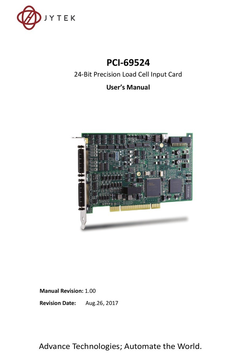
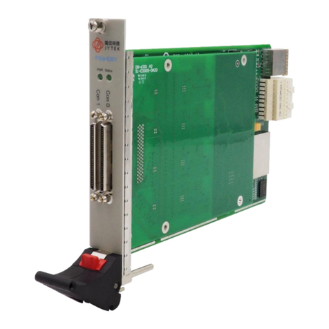
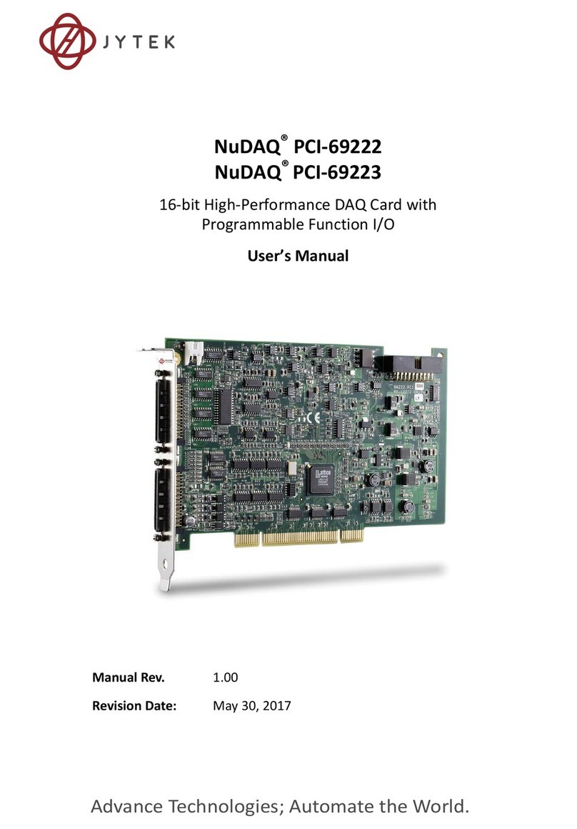
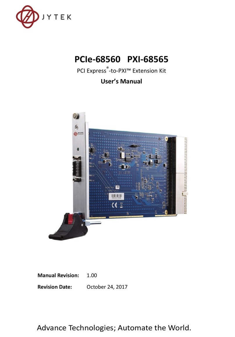
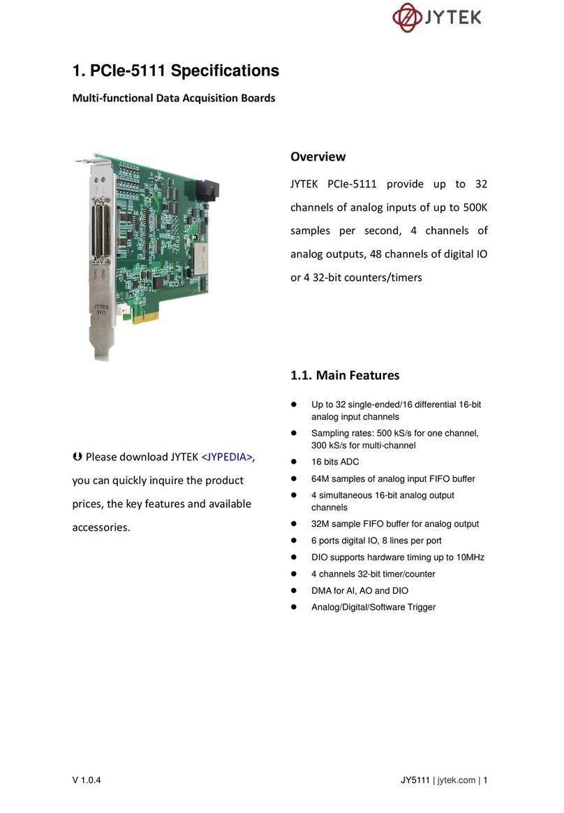
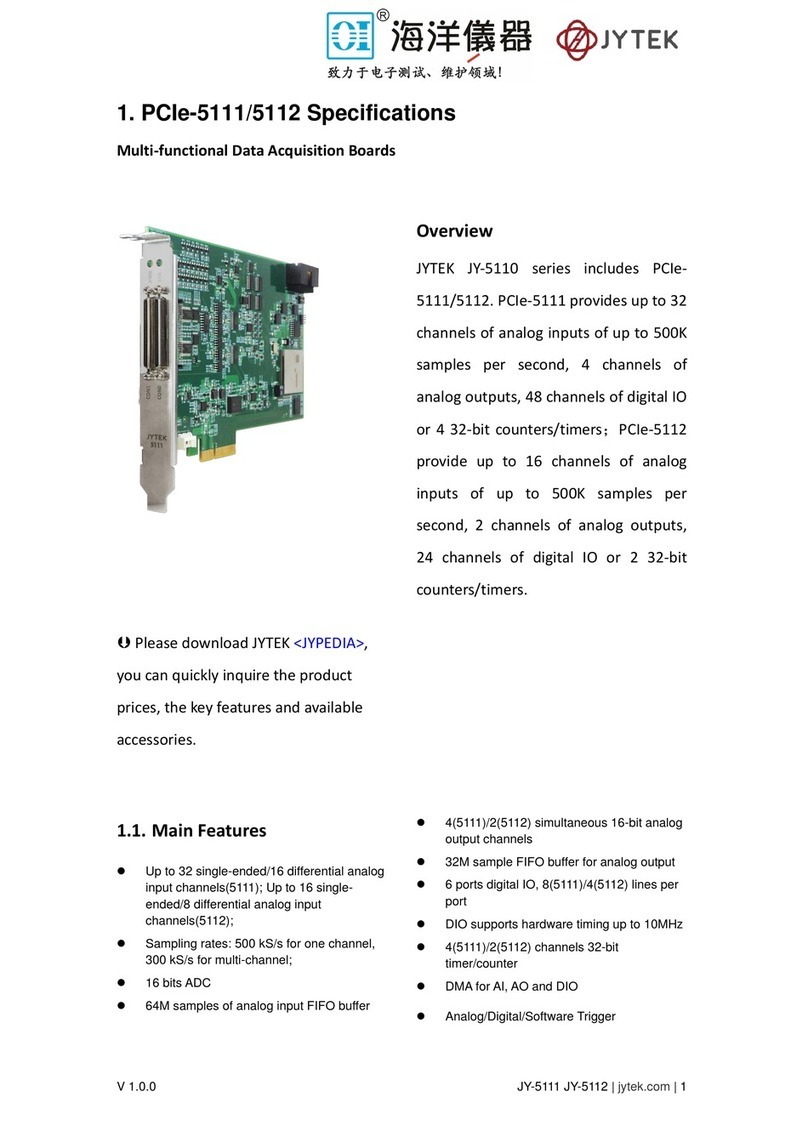
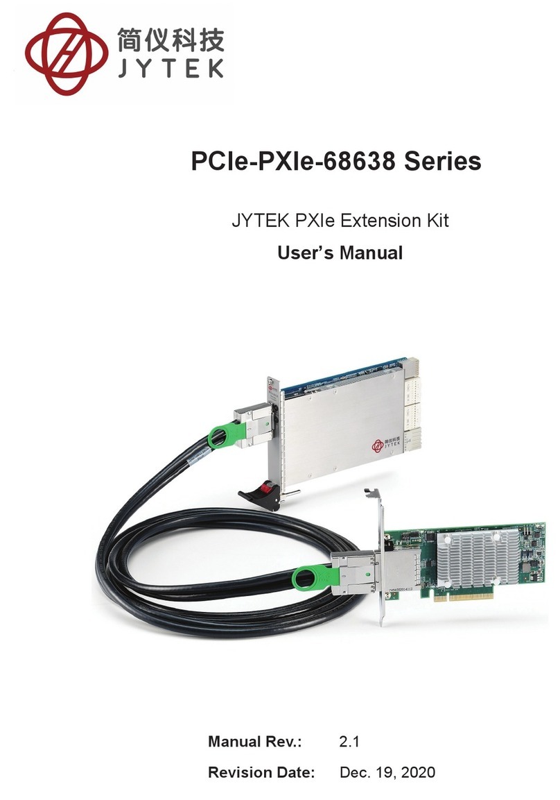
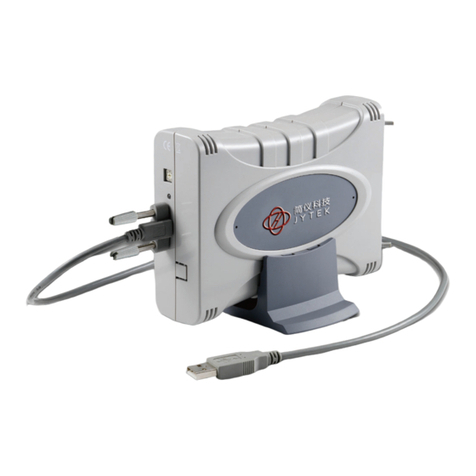
JYTEK 6743X Series User manual

Advance Technologies; Automate the World.
Manual Rev. 1.00
Revision Date: Mar 2, 2020
NuIPC / NuDAQ
6743X Series
64-CH Isolated Digital I/O Cards
User’s Manual

How to Use This Manual
This manual is designed to help you use the 6743X series prod-
ucts. It describes how to modify and control various functions of
the 6743X card to meet the requirements of your application. It is
divided into four chapters:
Chapter 1, “Introduction”, gives an overview of the product fea
tures, applications, and specifications.
Chapter 2, “Getting Started”, describes how to install the
board. The PCB layout, connector specifications, and installa-
tion notes are also described.
Chapter 3, “Registers”, describes the details of the registers
and its structure. This information is important for program-
mers who want to control the hardware with low-level program-
ming
Chapter 4, “Operation Theory”, describes the Isolated digital
input and output channels.
Warranty Information: Presents important warranty informa-
tion for users/manufacturers rights and responsibilities regard-
ing JYTEK products and services.
Getting Service: Contact information for JYTEK’s worldwide
offices.
Copyright
This document contains proprietary information protected by
copyright. All rights are reserved. No part of this manual may be
reproduced by any mechanical, electronic, or other means in any
form without prior written permission of the manufacturer. All
specifications are subject to change without further notice.

Table of Contents i
Table of Contents
Table of Contents............................................................................ i
List of Tables .................................................................................. iii
List of Figures................................................................................. iv
1 Introduction.............................................................................. 1
1.1 Features ......................................................................................... 2
1.2 Applications ................................................................................... 3
1.3 Specifications ................................................................................. 3
Optical Isolated Input Channel ................................................3
Optical Isolated Output Channel ..............................................4
General Specifications ..............................................................5
1.4 Supporting Software...................................................................... 5
Programming Library ................................................................6
2 Getting Started ......................................................................... 7
2.1 What You Have .............................................................................. 7
2.2 Unpacking ...................................................................................... 8
2.3 PCB Layout ..................................................................................... 9
PCI-6743X PCB Layout ..............................................................9
PXI-6743X PCB Layout ..............................................................9
2.4 Hardware Installation Outline ..................................................... 10
2.5 Device Installation for Windows Systems.................................... 12
2.6 PCI-67432, PXI-67432 Connector Pin Assignment ....................... 13
2.7 PXI-67432P Connector Pin Assignment ....................................... 15
2.8 PXI-67433 & PCI-67433 Connector Pin Assignment .................... 17
2.9 PCI-67434 Connector Pin Assignment ......................................... 19
2.10 PXI-67434P Connector Pin Assignment ....................................... 21
2.11 Jumpers Setting ........................................................................... 23
3 Registers ................................................................................. 25
3.1 PCI PnP Registers ......................................................................... 25
3.2 I/O Address Map.......................................................................... 26
3.3 Digital Input Register ................................................................... 27
3.4 Digital Output Register ................................................................ 28
4 Operation Theory.................................................................... 29

ii Table of Contents
4.1 Isolated Digital Input Channels.................................................... 29
4.2 Isolated Digital Output Channels................................................. 30
Common Ground (Sinking Current) ....................................... 31
Common Power (Sourcing Current) ....................................... 32
Warranty Policy ............................................................................ 33
Getting Service ............................................................................. 35

List of Tables iii
List of Tables
Table 1-1: Features Between Different 6743X Models ...................... 2
Table 1-2: Optical Isolated Input Channel Specifications ................... 3
Table 1-3: Optical Isolated Output Channel Specifications ................ 4
Table 2-1: 67432 CN1 Connector Pin Assignment ............................ 13
Table 2-2: PXI-67432P CN1 Connector Pin Assignment .................... 15
Table 2-3: 67433 CN1 ConnectorPin Assignment ............................. 17
Table 2-4: PCI-67434 CN1 Connector Pin Assignment ...................... 19
Table 2-5: PXI-67434P CN1 Connector Pin Assignment .................... 21
Table 2-6: PCI-67433 Jumper Settings .............................................. 23
Table 3-1: PCI/PXI-67432/33/34 I/O Address Map ........................... 26
Table 3-2: IDI_N: Isolated Digital Input CH N .................................... 27
Table 3-3: IDO_N: Isolated Digital Output CH N ............................... 28
Table 4-1: Device Support for Digital Output Types ......................... 30

iv List of Figures
List of Figures
Figure 2-1: PCI-6743X PCB Layout ........................................................ 9
Figure 2-2: PXI-6743X PCB Layout ........................................................ 9
Figure 2-3: Simplified Digital Input Circuit Diagram ........................... 24
Figure 2-4: PCI-67433 (rev. B2) Jumper Locations ............................. 24
Figure 4-1: Isolated Input Connection................................................ 29
Figure 4-2: Common Ground Output Architecture Block Diagram .... 31
Figure 4-3: Common Power Output Architecture Block Diagram ...... 32

Introduction 1
1 Introduction
The 6743X series products are 64-CH high-density isolated digital
input and/or output cards. The 6743X series products include the
following cards and are available in different form factors.
The following items are PCI bus products:
PCI-67432: Isolated 32-CH DI and 32-CH DO card
PCI-67433: Isolated 64-CH DI card
PCI-67434: Isolated 64-CH DO card
The following items are 3U CompactPCI products:
PXI-67432 : Isolated 32-CH DI and 32-CH DO card
PXI-67433 : Isolated 64-CH DI card
PXI-67434 : Isolated 64-CH DO card with common ground
configuration
PXI-67434P: Isolated 64-CH DO card with common power
configuration
The above I/O cards are isolated up-to 5000 Vdc (excluding
cables) for channel-to-computer isolation. It protects your com-
puter against damage caused by accidental contact with high
external voltage and eliminates troublesome ground loops.
The 6743X series products use PCI-9050 PCI controller to inter-
face the board to the PCI bus. The PCI-9050 fully implements the
PCI local bus specification Rev 2.1. All bus relative configurations,
such as base memory and interrupt assignment, are automatically
controlled by BIOS software.

2 Introduction
1.1 Features
The PCI-6743X Isolated D/I cards provide the following advanced
features:
PCI bus PCI-67432 PCI-67433 PCI-67434
3U PXI PXI-67432 PXI-67433 PXI-67434
PXI-67434P
32 isolated digital input / output
channels -- --
64 isolated digital input
channels -- --
64 isolated digital output
channels -- --
High output driving capability --
500 mA sink current on isolated
output channels --
5000 VRMS high voltage
isolation a
a.For PCI-67433, the isolation voltage is up to 2500 Vrms.
a
Up to 24 V voltage protection
for isolated input --
External interrupt signal on DI
channels --
Dual interrupt trigger --
100-pin SCSI-II connector
Table 1-1: Features Between Different 6743X Models

Introduction 3
1.2 Applications
Laboratory and Industrial automation
Watchdog timer
Event counter
Frequency counter and generator
Low level pulse generator
Time delay
1.3 Specifications
1.3.1 Optical Isolated Input Channel
PCI-67432
PXI-67432
PXI-67432P
PCI-67433
PXI-67433
Number of
Channels 32 DI 64 DI
Input Voltage
0 – 24 VDC
Logic H: 5-24 V
Logic L: 0-1.5 V
Input
Resistance
2.4 KΩ@0.5W
(2.4 KΩ @ 1 W for PCI-67433)
Isolated
Voltage
5000 Vrms
(2500 VRMS for PCI-67433,PXI-67432P)
Throughput 10 kHz (0.1 ms)
Interrupt
Sources Digital input channel 0 and channel 1
Power
Consumption +5 V @ 530 mA typical +5 V @ 500 mA typical
Table 1-2: Optical Isolated Input Channel Specifications

4 Introduction
1.3.2 Optical Isolated Output Channel
PCI-67432
PXI-67432
PXI-67432P
PCI-67433
PXI-67433
Number of
Channels 32 DO 64 DO
Output Type Darlington transistor with common
ground/common power
Output Voltage 5 VDC min, 35 VDC maximum
Output Device ULN2803A (common ground)
TD62783 (common power)
Sink Current
Max. 500 mA/ch if only one of the
ULN2083A transistor is ON
500 mA/ch if all of the ULN2803A transis-
tors are ON @ 20% duty (Tamb = 50?)
Max. 2.25 W per ULN2803A device
Isolated
Voltage
5000 Vrms
(2500 VRMS for PXI-67432P)
Throughput 10 kHz (0.1 ms)
On Board
Isolated +5V
Output Power
200 mA 150 mA
Power
Consumption +5 V @ 530 mA typical +5 V @ 500 mA typical
Table 1-3: Optical Isolated Output Channel Specifications

Introduction 5
1.3.3 General Specifications
Connector: 100-pin SCSI-II connector
Operating temperature: 0°C - 60°C
Storage temperature: -20°C - 80°C
Humidity: 5 - 95%, non-condensing
Dimensions:
PCI-67432/33/34: Compact size only 106mm(H) X
173mm(L)
PXI-67432/33/34: Standard 3U PXI form factor
1.4 Supporting Software
JYTEK provides versatile software drivers and packages for users’
different approach to building a system. We not only provide pro-
gramming libraries such as DLL for many Windows systems, but
also provide drivers for many other software package.
All software options are included in the JYTEK website.

6 Introduction
1.4.1 Programming Library
For customers who are writing their own programs, we provide
function libraries for many different operating systems, including:
DOS Library: Borland C/C++ and Microsoft C++, the func-
tions descriptions are included in this user’s guide.
Windows 95 DLL: For VB, VC++, Delphi, BC5, the func-
tions descriptions are included in this user’s guide.
PCIS-DASK: Includes device drivers and DLL for Windows
2000/XP/Vista. DLL is binary compatible across Windows
2000/XP/Vista. This means all applications developed with
PCIS-DASK are compatible across Windows 2000/XP/
Vista. The developing environment can be VB, VC++, Del-
phi, BC5, or any Windows programming language that
allows calls to a DLL. The user’s guide and function refer-
ence manual of PCIS-DASK are in the CD. Please refer to
the PDF manual files under \\Manual\Software Pack-
age\PCIS-DASK
The above software drivers are on the JYTEK website. Please
refer to www.jytek.com for installation procedures.

Getting Started 7
2 Getting Started
This chapter describes how to install and setup the 6743X Series
cards. The contents in the package and unpacking information
that you should be aware of are outlined first.
2.1 What You Have
In addition to the User’s Manual, the package should include the
following items:
6743X Board
If any of these items are missing or damaged, contact JYTEK from
whom you purchased the product. Save the shipping materials
and carton in case you want to ship or store the product in the
future.

8 Getting Started
2.2 Unpacking
The PCI-67432/33/34 card contains electro-static sensitive com-
ponents that can be easily be damaged by static electricity.
Therefore, the card should be handled on a grounded anti-static
mat. The operator should be wearing an anti-static wristband,
grounded at the same point as the anti-static mat.
Inspect the card module carton for obvious damage. Shipping and
handling may cause damage to your module. Be sure there is no
shipping and handling damage on the modules carton before con-
tinuing.
After opening the card module carton, extract the system module
and place it only on a grounded anti-static surface with component
side up.
Again, inspect the module for damage. Press down on all the
socketed IC's to make sure that they are properly seated. Do this
only with the module place on a firm flat surface
Note:DO NOT ATTEMPT TO INSTALL A DAMAGED BOARD IN
THE COMPUTER.
You are now ready to install your card.

Getting Started 9
2.3 PCB Layout
2.3.1 PCI-6743X PCB Layout
CN1 is the I/O interface and is a 100-pin SCSI-type connector.
Figure 2-1: PCI-6743X PCB Layout
2.3.2 PXI-6743X PCB Layout
CN1 is the I/O interface and is a 100-pin SCSI-type connector.
Figure 2-2: PXI-6743X PCB Layout

10 Getting Started
2.4 Hardware Installation Outline
PCI Configuration
The PCI cards (or PXI cards) are equipped with plug and play PCI
controllers that can request base addresses and interrupts accord-
ing to the PCI standard. The system BIOS will assign the system
resources based on the PCI cards’ configuration registers and
system parameters (which are set by the system BIOS). Interrupt
assignment and memory usage (I/O port locations) can only be
assigned by the system BIOS. These system resource assign-
ments are done on a board-by-board basis. It is not suggested to
assign the system resource by any other methods.
PCI Slot Selection
The PCI card can be inserted into any PCI slot without any config-
uration of the system resources. The PXI card can also be
inserted into any PXI I/O slot.
Installation Procedures
1. Turn off your computer
2. Turn off all accessories (printer, modem, monitor, etc.)
connected to your computer.
3. Remove the cover from your computer.
4. Setup jumpers on the PCI or PXI card.
5. Select a 32-bit PCI slot. PCI slot are shorter than ISA or
EISA slots, and are usually white or ivory.
6. Before handling the PCI cards, discharge any static
buildup on your body by touching the metal case of the
computer. Hold the edge and do not touch the compo-
nents.
7. Position the board into the PCI slot you selected.
8. Secure the card in place at the rear panel of the system.

Getting Started 11
For PXI-6743X Products
1. Read through this manual, and setup the jumper accord-
ing to your application needs.
2. Turn off your computer and all accessories (printer,
modem, monitor, etc.) connected to the computer.
3. Remove the cover from the slot of your PXI computer.
4. Select a 32-bit PXI expansion slot on the back plane for
PXI-6743X card.
5. Before handling the PXI-6743X card, discharge any
static buildup from your body by touching the metal cas-
ing of the computer. Hold the edge and do not touch the
components.
6. Position the board into the PXI slot you selected.
7. Secure the card on the back plane by using screws
removed from the slot.

12 Getting Started
2.5 Device Installation for Windows Systems
Once Windows 2000/XP/Vista has started, the Plug and Play func-
tions of the Windows system will find and locate the new NuDAQ/
NuIPC card. If this is the first time a NuDAQ/NuIPC card is
installed in your Windows system, you will be prompted to input
the device information source. Please refer to the JYTEK website
for installation procedures of the device drivers.

Getting Started 13
2.6 PCI-67432, PXI-67432 Connector Pin Assignment
The pin assignment of the 100-pin SCSI-II connector for the 67432
Series is shown in Table 2-1 below.
Table 2-1: 67432 CN1 Connector Pin Assignment
(1) IDI_0 (26) IDO_0 (51) IDI_8 (76) IDO_8
(2) IDI_1 (27) IDO_1 (52) IDI_9 (77) IDO_9
(3) IDI_2 (28) IDO_2 (53) IDI_10 (78) IDO_10
(4) IDI_3 (29) IDO_3 (54) IDI_11 (79) IDO_11
(5) IDI_4 (30) IDO_4 (55) IDI_12 (80) IDO_12
(6) IDI_5 (31) IDO_5 (56) IDI_13 (81) IDO_13
(7) IDI_6 (32) IDO_6 (57) IDI_14 (82) IDO_14
(8) IDI_7 (33) IDO_7 (58) IDI_15 (83) IDO_15
(9) COM1 (34) VDD1 (59) COM2 (84) VDD2
(10) COM1 (35) IGND (60) COM2 (85) IGND
(11) COM1 (36) IGND (61) COM2 (86) IGND
(12) COM1 (37) IGND (62) COM2 (87) IGND
(13) IDI_16 (38) IDO_16 (63) IDI_24 (88) IDO_24
(14) IDI_17 (39) IDO_17 (64) IDI_25 (89) IDO_25
(15) IDI_18 (40) IDO_18 (65) IDI_26 (90) IDO_26
(16) IDI_19 (41) IDO_19 (66) IDI_27 (91) IDO_27
(17) IDI_20 (42) IDO_20 (67) IDI_28 (92) IDO_28
(18) IDI_21 (43) IDO_21 (68) IDI_29 (93) IDO_29
(19) IDI_22 (44) IDO_22 (69) IDI_30 (94) IDO_30
(20) IDI_23 (45) IDO_23 (70) IDI_31 (95) IDO_31
(21) COM3 (46) VDD3 (71) COM4 (96) VDD4
(22) COM3 (47) IGND (72) COM4 (97) IGND
(23) COM3 (48) IGND (73) COM4 (98) IGND
(24) COM3 (49) IGND (74) COM4 (99) IGND
(25) NC (50) V5V (75) NC (100) V5V

14 Getting Started
Legend:
IDI_n: Isolated digital input channel n
IDO_n: Isolated digital output channel n
VDDm: Common pin for output channel group m (VDD1 is
common pin for isolated output channel 0-7,
VDD2 is common pin for isolated output channel
8-15, and so on).
IGND: Ground return path for isolated output channels
COMm: Common junction for isolated input channel group
m (COM1 is common junction for input channel 0-
7, COM2 is common junction for input channel 8-
15, and so on).
V5V: Onboard un-regulated 5 V power supply output
This manual suits for next models
7
Table of contents
Other JYTEK Computer Hardware manuals

JYTEK
JYTEK PCI-69524 User manual

JYTEK
JYTEK USB-62401 User manual

JYTEK
JYTEK PCIe-6301 Series User manual

JYTEK
JYTEK PCIe-5111 User manual

JYTEK
JYTEK PCIe/PXIe-6301 Series User manual

JYTEK
JYTEK JY-5110 Series User manual

JYTEK
JYTEK USB-62405 User manual

JYTEK
JYTEK PCIe-68638 Series User manual

JYTEK
JYTEK NuDAQ PCI-69222 User manual

JYTEK
JYTEK PCIe-68560 User manual