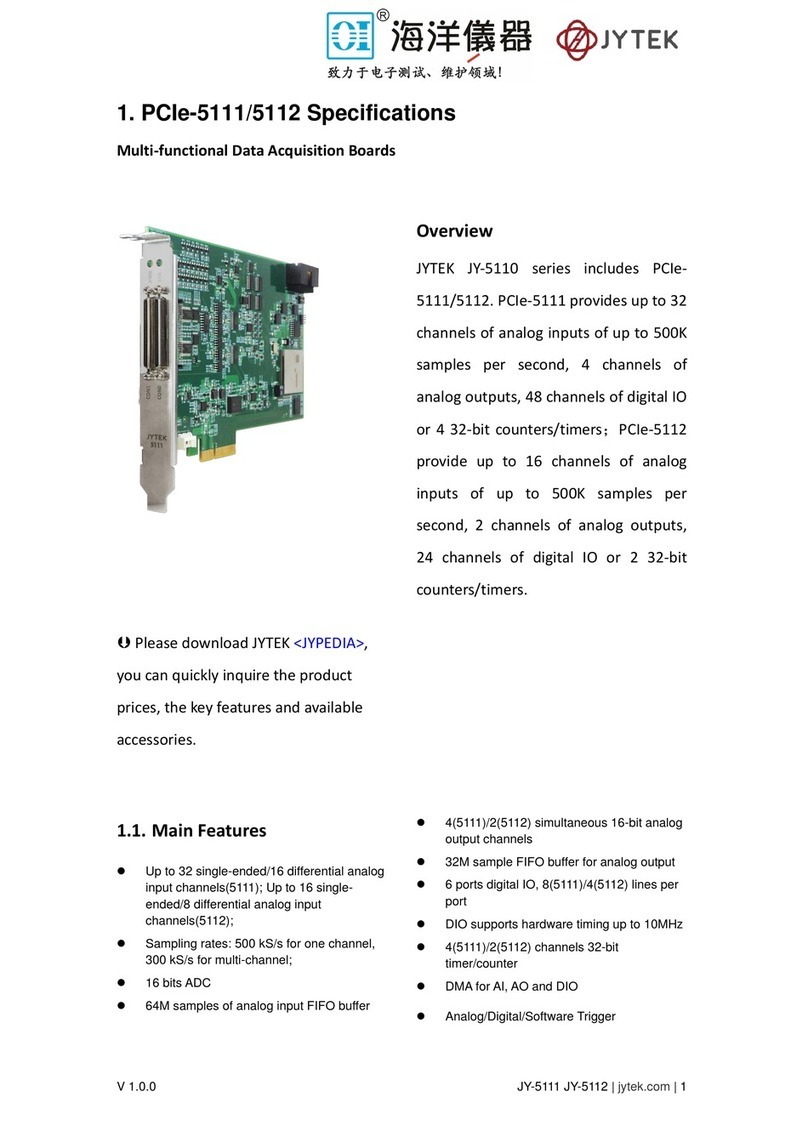
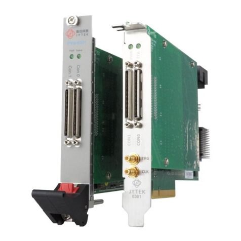
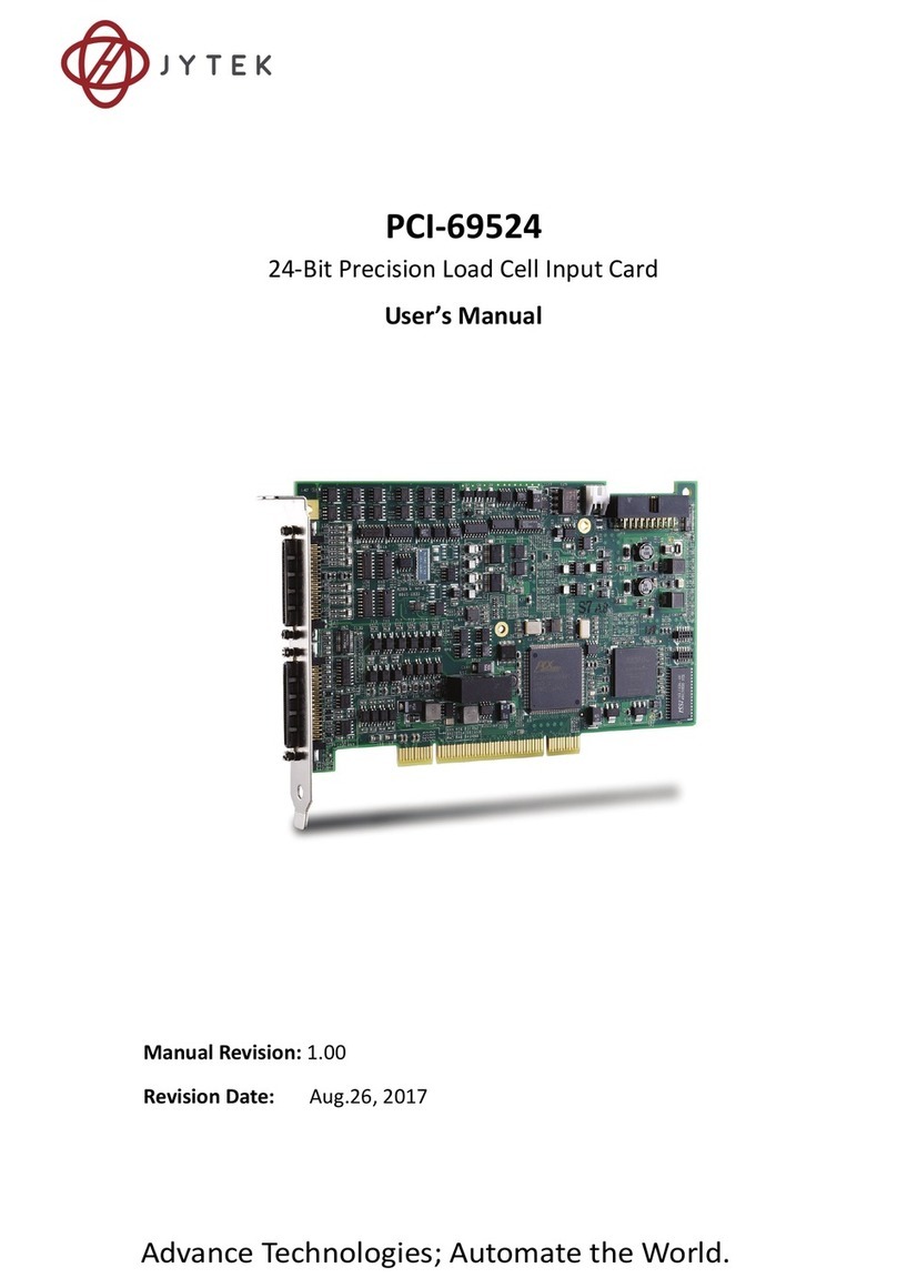
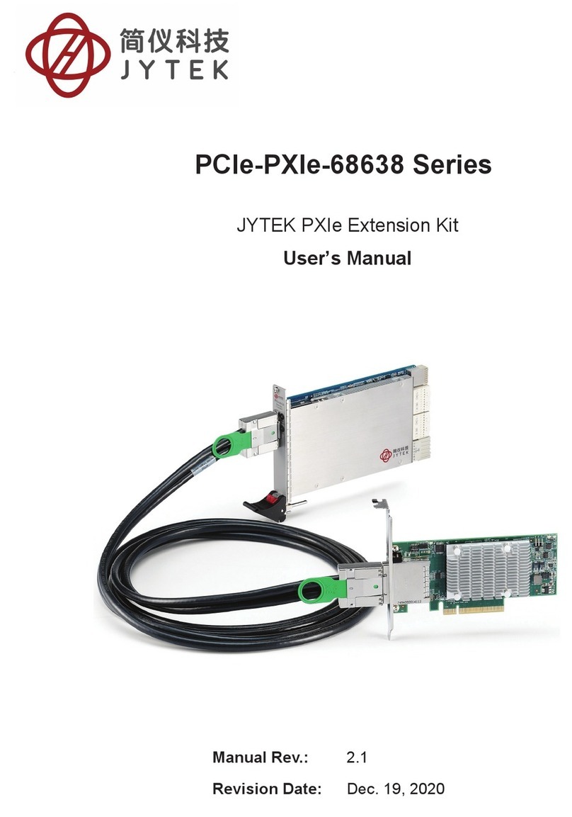
JYTEK PCIe-68560 User manual

Advance Technologies; Automate the World.
Manual Revision: 1.00
Revision Date: October 24, 2017
PCIe-68560 PXI-68565
PCI Express®-to-PXI™ Extension Kit
User’s Manual

ii

Preface iii
Preface
Copyright
This document contains proprietary information protected by copyright.
All rights are reserved. No part of this manual may be reproduced by any
mechanical, electronic, or other means in any form without prior writ-
ten permission of the manufacturer. All specifications are subject to
change without further notice.
Disclaimer
The information in this document is subject to change without prior
notice in order to improve reliability, design, and function and does not
represent a commitment on the part of the manufacturer.
In no event will the manufacturer be liable for direct, indirect, special,
incidental, or consequential damages arising out of the use or inability
to use the product or documentation, even if advised of the possibility
of such damages.
Trademarks
PCI Express® is a registered trademark of the Peripheral Component
Interconnect Special Interest Group. PXI™ is a trademark of the PXI
Systems Alliance.
Product names mentioned herein are used for identification purposes
only and may be trademarks and/or registered trademarks of their
respective companies.

iv Preface
Using this Manual
Audience and Scope
The PCIe-68560 PXI-68565 User’s Manual is intended for hardware
technicians and systems operators with knowledge of installing, config-
uring and using PCI Express®-to-PXI™ extension systems. This document
is specifically intended to describe connecting JYTEK PCIe-68560 PCI
Express® Systems to a PXI™ Extension Kit for extended functionality.
Manual Organization
This manual is organized as follows:
Preface: Presents important copyright notifications, disclaimers,
trademarks, and associated information on the proper understand-
ing and usage of this document and its associated product(s).
Chapter 1, Introduction: Introduces the PCI Express® to PXI™ Exten-
sion Kit overview, its features, applications, architecture, block dia-
grams, and package contents.
Chapter 2, Getting Started: Presents information on properly install-
ing PCI Express® and PXI™ equipment and cabling a PCI Express® to
PXI™ extension kit.
Chapter 3, Hardware Information: Presents layout information,
technical drawings, jumper settings, and configuration.
Chapter 4, Troubleshooting: Provides basic information on quickly
addressing configuration/setup/installation problems that may
occur.
Important Safety Instructions: Presents safety instructions all users
must follow for the proper setup, installation and usage of equip-
ment and/or software.
Warranty Information: Presents important warranty information for
users/manufacturers rights and responsibilities regarding JYTEK
products and services.
Getting Service: Contact information for JYTEK’s worldwide offices.

Preface v
Conventions
Take note of the following conventions used throughout this manual to
make sure that users perform certain tasks and instructions properly.
NOTE:
NOTE:
Additional information, aids, and tips that help users perform
tasks.
CAUTION:
Information to prevent minor physical injury, component
damage, data loss, and/or program corruption when trying to
complete a task.
WARNING:
Information to prevent serious physical injury, component
damage, data loss, and/or program corruption when trying to
complete a specific task.

vi Preface
Reference Documentation
The following list of documents may be used as reference materials to
support installation, configuration and/or the operation of the PCI
Express-to-PXI Extension Kit. This list is prepared in alphabetical order
(by vendor name, then by document title) for clarity.
Vendor(s)/Association(s) Title Rev.
PCI-SIG PCI Express® Base Specification 1.0a
PCI-SIG PCI-to-PCI Bridge Architecture
Specification
1.2
PCI-SIG PCI Local Bus Specification 3.0
PXI System Alliance PXI Specification 2.2

Table of Contents vii
Table of Contents
Preface .......................................................................................... iii
Table of Contents.......................................................................... vii
List of Figures................................................................................. ix
List of Tables .................................................................................. xi
1 Introduction.............................................................................. 1
1.1 Overview........................................................................................ 1
1.1.1Controlling PXI™ with PCI Express®..............................................1
1.2 Package Contents .......................................................................... 3
1.3 Specifications ................................................................................. 4
1.4 Features ......................................................................................... 5
1.5 Applications ................................................................................... 5
2 Getting Started ......................................................................... 7
2.1 Installation Environment ............................................................... 7
2.2 Installing PCIe-68560 on a Host Computer.................................... 8
2.3 Installing PXI-68565 to a PXI™ Chassis......................................... 10
2.4 Cabling Host Computer to PXI™ Extension Chassis ..................... 11
2.5 Power-ON/OFF Sequence ............................................................ 14
2.6 LED Status .................................................................................... 15
3 Hardware Information ............................................................ 17
3.1 Functional Block Diagram ............................................................ 17
3.2 PCIe-68560 Layout, Connectors and Jumpers ............................. 18
3.2.1PCIe-68560 S1/S2 Signal Equalizer Adjustments........................19
3.3 PXI-68565 Layout, Connectors and Jumpers ............................... 21
3.4 Extension Cable Options .............................................................. 23
4 Troubleshooting (FAQ) ............................................................ 25
Important Safety Instructions ...................................................... 29
Warranty Policy ........................................................................... 31
Getting Service............................................................................. 33
List of Figures ix
List of Figures
Figure 2-1: PCIe-68560 to Host PC Installation Diagram.............................9
Figure 2-2: PXI-68565 to PXI™ Chassis Installation Diagram .....................10
Figure 2-3: 3 M extension cable (ACL-EXPRESS-3)..................................... 11
Figure 2-4: Cabling 3 M Extension Cable to Host PC .................................12
Figure 2-5: Cabling 3 M Extension Cable to PXI™ Extension Chassis.........13
Figure 2-6: Host PC connected to a PXI™ Extension Chassis .....................13
Figure 3-1: PCI Express-to-PXI Extension Kit Functional Block Diagram....17
Figure 3-2: PCIe-68560 Mechanical Layout...............................................18
Figure 3-3: PCI-68565 Mechanical Layout.................................................21
Figure 3-4: Standard 3 M extension cable (ALC-PCEEXT-3).......................23

List of Tables xi
List of Tables
Table 2-1: PCIe-68560 to Host PC Chassis Installation Items.....................9
Table 3-1: PCIe-68560 Connectors, Jumpers and LED .............................18
Table 3-2: PCIe-68560 Pin 1 and Pin 2 Equalizer Selection ......................19
Table 3-3: PCIe-68560 Pin 3 Output Swing Control .................................20
Table 3-4: PCIe-68560 Pin 4 Output De-Emphasis Control ......................20
Table 3-5: PXI-68565 Connectors, Jumpers and LED................................21
Table 3-6: PXI-68565 J1 Spread Spectrum Clock Control.........................22
Table 3-7: Optional Extension Cables.......................................................23

Introduction 1
1 Introduction
This chapter introduces the PCI Express-to-PXI Extension Kit, presents a
general overview and basic applications, its package contents, specifica-
tions, and features.
1.1 Overview
Harnessing the bandwidth potential of PCI Express®, the PCI Express-to-
PXI Extension Kit enables computers with a PCI Express® slot to remotely
manage and control PXI™ devices up to seven meters away, using the
high-speed PCI Express® interface. These extension systems operate in
32-bit/33 MHz configuration and come with complete end-to-end hard-
ware and software transparency for the host system. Hardware devices
installed in the extension system behave and work as if they are directly
installed into the host system, requiring no additional drivers or soft-
ware installation.
The host system may be separated from the extension system at up to
seven meters using high-quality shielded twisted copper cables. The
robust and reliable PCI Express-to-PXI Extension Kit is suited for portable
test and measurement applications with high-density I/O requirement
and in hazardous industrial control and automation environments.
1.1.1 Controlling PXI™ with PCI Express®
Based on PCI Express® technology, the PCI Express-to-PXI Extension Kit
provides bus expansion capability through its high-speed differential sig-
nal interface. The PCI Express-to-PXI Extension Kit uses a signal equalizer
and a PCI Express-to-PCI bridge. With JYTEK’s PCI Express-to-PXI Exten-
sion Kit, users can utilize an available PCI Express® slot to control an
external PXI™ chassis. Because the PCI Express® bridge is transparent,
there is no need to install any additional software when using PXI™
devices in the external chassis.

2 Introduction
The PCI Express-to-PXI Extension Kit implements a PCI Express-based
control of PXI™ modules. The technology consists of a PCIe-68560 card
installed in a host computer, a shielded cable, and a PXI-68565 card
installed in the remote PXI™ chassis. The PCIe-68560 comes in a PCI
Express® x1 footprint and communicates with the PXI-68565 via a
twisted and shielded cable. The PXI-68565 converts the PCI Express®
interface into a PCI interface for additional PXI™ slots in the extension
system.
The link between host PC and the external chassis is a PCI Express® X1
link that represents a dual-simplex communications channel consisting
of two, low-voltage differentially driven signal pairs. The signaling rate
can reach up to 2.5 Gbps in each direction. Using a shielded and twisted
cable, the maximum extension distance can be up to 7 M without
decreasing signal rate.

Introduction 3
1.2 Package Contents
PCI Express-to-PXI Extension Kit
PCIe-68560 (PCI Express® extension host card)
PXI-68565 (PCI Express® controller for PXI™ interface)
ACL-EXPRESS-3 (3 M extension cable)
NOTE:
NOTE:
If any of the items on the contents list are missing or dam-
aged, contact your JYTEK dealer.

4 Introduction
1.3 Specifications
PCIe-68560 (on host computer)
Compliant with PCI Express® Base Specifications Rev. 1.0a
PCI Express® x1 link which provides an effective signaling rate of
up to 2.5 Gigabits/sec.
Maximum extended distance of up to seven meters
Low-profile footprint, 68.90 mm (H) x 86.65 mm (W)
Power requirement: 3.3 V, 210 mA (max)
PXI-68565 (on extension PXI™ chassis)
Compliant with PCI-to-PCI Bridge Architecture Specifications Rev.
1.2
Supports 5 V and 3.3 V PCI bus
32-bit/33 MHz full data throughput
Maximum extended distance of up to seven meters
Power requirement: +3.3 V, 720 mA
Operating and Storage Environments
Operating temperature: 0°C to 50°C
Storage temperature: -20°C to 80°C
Relative humidity: 10% to 90%, non-condensing

Introduction 5
1.4 Features
PCI Express® control of PXI™ cards
High-speed PCI Express® X1 interface
Compatible with 5 V and 3.3 V PCI bus
Supports 32-bit/33 MHz PCI interface
Extension lengths of 1 M, 3 M and 7 M
Complete hardware and software transparency
Compliant with PCI Express® Base Specification, Revision 1.0a
Compliant with PCI-to-PCI Bridge Architecture Specification, Revision
1.2
Compliant with PCI Local Bus Specification, Revision 3.0
1.5 Applications
These extension systems are suitable for:
Electronics manufacturing testing
High-density I/O systems
Industrial automation and control
Military and aerospace
Testing systems for remote and/or harsh environments
Video capture

6 Introduction
This page intentionally left blank.

Getting Started 7
2 Getting Started
This chapter describes the installation environment, installation proce-
dures, cabling the equipment, and instructions on powering-on/off the
PCI Express-to-PXI Extension Kit.
2.1 Installation Environment
Whenever unpacking and preparing to install any equipment described
in this manual, please refer to the Important Safety Instructions chapter
of this manual.
Only install equipment in well lit areas on flat, sturdy surfaces with
access to basic tools such as flat and cross head screwdrivers.
The PCI Express-to-PXI Extension Kit contains several electro-static sensi-
tive components that can be easily damaged by static electricity. For this
reason, the cards and chassis should be handled on a grounded anti-
static mat and the operator should wear an anti-static wristband during
the unpacking and installation procedure.
Please also inspect the components for apparent damage. Improper
shipping and handling may cause damage to the components. Be sure
there is no shipping and handling damage on the components before
continuing.
NOTE:
NOTE:
Diagrams and images of equipment mentioned are used for
reference only. Actual system appearance may vary.
CAUTION:
Do not apply power to any equipment if it has been damaged.

8 Getting Started
2.2 Installing PCIe-68560 on a Host Computer
1. Power-off your host computer.
2. Unscrew the housing of your host computer using a (cross-
head or flat-head) screwdriver. Open the housing.
3. Locate your PCI Express® extension card (PCIe-68560) and
remove it from its packaging. (Please wear anti-static gloves
and use an anti-static surface when handling the card).
4. Install the PCIe-68560 in an available X1 PCI Express® slot in
your host computer. Be sure to firmly attach the PCIe-68560’s
bracket to the backplane of the host PC.
5. Close the chassis and re-install its housing screws.
This manual suits for next models
1
Table of contents
Other JYTEK Computer Hardware manuals

JYTEK
JYTEK PCIe/PXIe-6301 Series User manual

JYTEK
JYTEK USB-62401 User manual

JYTEK
JYTEK PCIe-5111 User manual

JYTEK
JYTEK PCIe-68638 Series User manual

JYTEK
JYTEK USB-62405 User manual

JYTEK
JYTEK 6743X Series User manual

JYTEK
JYTEK PCIe-6301 Series User manual

JYTEK
JYTEK JY-5110 Series User manual

JYTEK
JYTEK NuDAQ PCI-69222 User manual

JYTEK
JYTEK PCI-69524 User manual