JYTEK PCIe-5111 User manual

V 1.0.4 JY5111 | jytek.com | 1
1. PCIe-5111 Specifications
Multi-functional Data Acquisition Boards
Please download JYTEK <JYPEDIA>,
you can quickly inquire the product
prices, the key features and available
accessories.
Overview
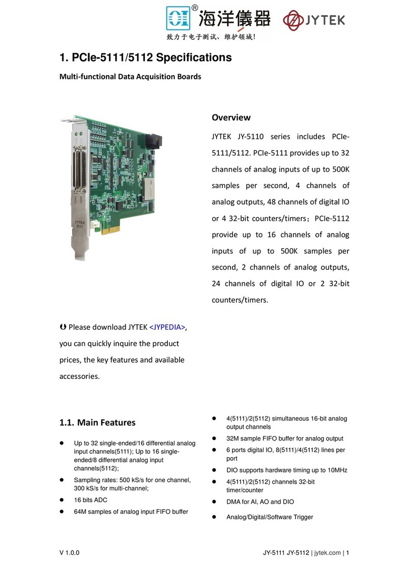
JYTEK PCIe-5111 provide up to 32
channels of analog inputs of up to 500K
samples per second, 4 channels of
analog outputs, 48 channels of digital IO
or 4 32-bit counters/timers
1.1. Main Features
⚫Up to 32 single-ended/16 differential 16-bit
analog input channels
⚫Sampling rates: 500 kS/s for one channel,
300 kS/s for multi-channel
⚫16 bits ADC
⚫64M samples of analog input FIFO buffer
⚫4 simultaneous 16-bit analog output
channels
⚫32M sample FIFO buffer for analog output
⚫6 ports digital IO, 8 lines per port
⚫DIO supports hardware timing up to 10MHz
⚫4 channels 32-bit timer/counter
⚫DMA for AI, AO and DIO
⚫Analog/Digital/Software Trigger

V 1.0.4 JY5111 | jytek.com | 2
1.2. Analog Input
Table 1 Analog Input Specifications
Analog Input 5111
Number of channels 32 SE / 16 DIFF
ADC resolution (Bits) 16
Single channel maximum sample
rate
500K Samples/s
Multichannel maximum sample rate
with same range(aggregate)
300K Samples/s
Multichannel maximum sample rate
with different range(aggregate)
100K Samples/s
Clock 100 MHz
Input range(V) ±10/±5/±2.5/±1.25/±0.625
Input mode RSE / NRSE / Differential
Input impedance >1 GΩ||100 pF
Input coupling DC
Overvoltage protection ±25 V
CMRR 85 dB
Crosstalk -80dB
DNL No Missing Code
INL 70 ppm of Range Typical
Input FIFO 64M Samples
Trigger type Digital, Analog, Software
Trigger mode StartTrigger, ReferenceTrigger, ReTrigger
Analog trigger voltage range ±10V Software Programmable
Continuous : 20m A, ±25 V
Instantaneous : 40 mA, ±25 V
Overvoltage Protection

V 1.0.4 JY5111 | jytek.com | 3
1.3. Analog Output
Table 2 Analog Output Specifications
1.4. Counter Input Operations
Table 3 Counter Input Operations Specifications
1.5. PFI Specifications
Table 4 PFI Specifications
Analog Output 5111
Number of channels 4
DAC resolution 16 bits
Maximum update
rate(simultaneous)
1 channel 2.86 M Sample/s
2 channels 2 M Sample/s
3 channels 1.54 M Sample/s
4 channels 1.25 M Sample/s
Clock 100 MHz
Clock accuracy Jitter <20 ps
Output range(V) ±10, ±5
Output mode RSE
Output impedance 2 ohm
Output coupling DC
Output current drive ±10 mA
Output FIFO 32M Samples
Trigger type Digital, Software
Trigger mode StartTrigger
Number of channels 4
Resolution 32
Counter Input
edge count, period measurement, frequency
measurement, pulse width measurement, two-edge
interval measurement, orthogonal coding, etc.
Counter Output Single, finite and continuous pulse
Clock 200 MHz
FIFO 4 M Samples
Input Gate,Source,Aux
Output OUT
Number of channels 16
Trigger voltage : 3.3 V TTL
Trigger edge: Rising/Falling
Initial state Input
External digital trigger interface

V 1.0.4 JY5111 | jytek.com | 4
1.6. Digital IO Specifications
Table 5 Digital IO Specifications
1.7. Basic DC AI Accuracy
Table 6 Basic Accuracy in DAQ Mode
1.8. AI Bandwidth
Table 7 AI Bandwidth Specifications
Number of channels Port(0,1,2,3,4,5), 8 channels per port
Ground reference D GND
Directional control Independent control of each port
Clock 10 MHz
DI FIFO 16M Samples
DO FIFO 16M Samples
Initial state Input
Logic Low: VIL Min : 0 / Max : 1.0 V
Logic High: VIH Min : 2 V / Max : 5.3 V)
Logic Low : 0 V, IOL Max: 24 mA
Logic High : 2.6 V~5 V, IOH: -24 mA~0 mA
Continuous 30 mA, -3.9 V~8.9 V Instantaneous 200 mA, ±25 V;
Duty cycle of instantaneous current pulse does not exceed 15%
Digital Input
Digital Output
Overvoltage Protection
JY5111 Basic Accuracy = ±(% Reading+% Range)
Nominal Range
(V)
24 Hr Full Scale Accuracy
0.625 0.0013 + 0.0544 348 uV
1.25 0.0014 + 0.0320 417 uV
2.5 0.0007 + 0.0207 534 uV
50.0016 + 0.0150 830 uV
10 0.0008 + 0.0109 1167 uV
Valid for one channel only. 95% of Confidence Interval
Max sampling rates for 5111: 250K
Add 20% to Gain and Offset Errors From 91 Days to 1 Year. Preliminary
10 V range: valid for ±9.5V
24 Hour Tcal ±1C°
±0.625
480
±5
390
±2.5
480
±1.25
480
Analog Input Bandwidth
Nominal Range Full Scale (V)
-3dB Bandwidth (KHz)
±10
325

V 1.0.4 JY5111 | jytek.com | 5
1.9. Basic AO Accuracy
Table 8 Basic AO Accuracy
1.10. System Noise
Table 9 System Noise Specifications Physical and Environment
1.11. Physical and Environment
Table 10 Physical and Environment
JY5111 Basic AO Accuracy = ±(% of Output+% of Range)
Nominal
Range (V)
24 Hr Full-Scale Accuracy
5 0.0014 + 0.0043 285 uV
10 0.0015 + 0.0033 486 uV
Valid for all update rates.
Add accuracy adjustment if temperature is ouside calibration temperature range.
Add 20% to Gain and Offset Errors From 91 Days to 1 Year. Preliminary.
Maximum update rates(simultaneous)
1 Ch: 1M; 2 Ch: 1M;
Specs subject to minor changes when more tests become available.
24 Hour Tcal ±1C°
Range SystemNoise (uV)
10 345
5252
2.5 211
1.25 169
0.625 144
Operating Environment
Ambient temperature range 0 °C to 50 °C
Relative humidity range 20% to 80%, noncondensing
Storage Environment
Ambient temperature range -20 ˚C to 80 ˚C
Relative humidity range 10% to 90%, noncondensing

V 1.0.4 JY5111 | jytek.com | 7
Pin Signal Name Pin Signal Name Pin Signal Name Pin Signal Name
1
PFI 14
/P5.6/DO_ECLK
35 D_GND 1 P3.6 35 D_GND
2 PFI 12/P5.4 36 D_GND 2 P3.4 36 D_GND
3 PFI 9/P5.1 37 PFI 8/P5.0 3 P3.1 37 P3.0
4 D_GND 38 PFI 7/P4.7 4 D_GND 38 P2.7
PFI 6
/P4.6/ AO_ECLK
6 PFI 5/P4.5 40 PFI 13/P5.5 6 P2.5 40 P3.5
7 D_GND 41 PFI 4/P4.4 7 D_GND 41 P2.4
8 +5V_OUT 42 PFI 3/P4.3 8 +5V_OUT 42 P2.3
9 D_GND 43
PFI 2
/P4.2/AI_ECLK
9 D_GND 43 P2.2
10 PFI 1/P4.1 44 DGND 10 P2.1 44 DGND
PFI10
/P5.2/DI_ECLK
12 D_GND 46 PFI 11/P5.3 12 D_GND 46 P3.3
13 D_GND 47 P0.3 13 D_GND 47 P1.3
14 +5V_OUT 48 P0.7 14 +5V_OUT 48 P1.7
15 D_GND 49 P0.2 15 D_GND 49 P1.2
16 P0.6 50 D_GND 16 P1.6 50 D_GND
17 P0.1 51 P0.5 17 P1.1 51 P1.5
18 D_GND 52 P0.0 18 D_GND 52 P1.0
19 P0.4 53 D_GND 19 P1.4 53 D_GND
20 APFI 0 54 AO_GND 20 APFI 1 54 AO_GND
21 AO 1 55 AO_GND 21 AO 3 55 AO_GND
22 AO 0 56 AI_GND 22 AO 2 56 AI_GND
23 AI 15(AI 7-)57 AI 7(AI 7+)23 AI 31(AI 23-)57 AI 23(AI 23+)
24 AI_GND 58 AI 14(AI 6-)24 AI_GND 58 AI 30(AI 22-)
25 AI 6(AI 6+)59 AI_GND 25 AI 22(AI 22+)59 AI_GND
26 AI 13(AI 5-)60 AI 5(AI 5+)26 AI 29(AI 21-)60 AI 21(AI 21+)
27 AI_GND 61 AI 12(AI 4-)27 AI_GND 61 AI 28(AI 20-)
28 AI 4(AI 4+)62 AI_SENSE 0 28 AI 20(AI 20+)62 AI_SENSE 1
29 AI_GND 63 AI 11(AI 3-)29 AI_GND 63 AI 27(AI 19-)
30 AI 3(AI 3+)64 AI_GND 30 AI 19(AI 19+)64 AI_GND
31 AI10(AI 2-)65 AI 2(AI 2+)31 AI26(AI 18-)65 AI 18(AI 18+)
32 AI_GND 66 AI 9(AI 1-)32 AI_GND 66 AI 25(AI 17-)
33 AI 1(AI 1+)67 AI_GND 33 AI 17(AI 17+)67 AI_GND
34 AI 8(AI 0-)68 AI 0(AI 0+)34 AI 24(AI 16-)68 AI 16(AI 16+)
Connector 0
Connector 1
5
11
PFI 0/P4.0
39
45
PFI 15/P5.7
5
11
P2.6
P2.0
39
45
P3.7
P3.2

V 1.0.4 JY5111 | jytek.com | 8
Table 11 5111 Pin Definition
Table 12 Cable Specification
Pin Signal Name Pin Signal Name
11 CTR0_Source/A 42 CTR1_Source/A
10 CTR0_Gate/Z 41 CTR1_Gate/Z
43 CTR0_AUX/B 6 CTR1_AUX/B
2 CTR0_ OUT 40 CTR1_ OUT
5 CTR2_Source/A 3 CTR3_Source/A
38 CTR2_Gate/Z 45 CTR3_Gate/Z
37 CTR2_AUX/B 46 CTR3_AUX/B
1 CTR2_ OUT 39 CTR3_ OUT
AI_GND Analog Input Reference Ground
AI<0..31> Analog Input channel
AI SENSE Analog Input Signal, Suitable for NRSE mode
AO_GND Analog Output Reference Ground
AO<0..3> Analog Output Channel
D_GND Digital Signal Reference Ground
P<0..3>.<0..7> Digital I/O Channel
PFI<0..15> Programmable Function Interface
+5V_OUT 5Vpower supply

V 1.0.4 JY5111 | jytek.com | 9
1.13. Accessories
⚫DIN-68S-01 (PN: JA9114029-01)
SCSI 68-pin Terminal board w/o cable
⚫TB-68 (PN: JY2000068-03)
68-Pin SCSI Shielded I/O Connector Block
⚫ACL-2006868-1 (PN: JY2006868-01)
1M 68pin VHDCI68M-SCSI68M cable
⚫ACL-2006868-2 (PN: JY2006868-02)
2M 68pin VHDCI68M-SCSI68M cable

V 1.0.4 JY5111 | jytek.com | 10
2. Table of Contents
Table of Contents
1. PCIe-5111 Specifications...............................................................................................1
1.1. Main Features...............................................................................................................1
1.2. Analog Input..................................................................................................................2
1.3. Analog Output...............................................................................................................3
1.4. Counter Input Operations.............................................................................................3
1.5. PFI Specifications ..........................................................................................................3
1.6. Digital IO Specifications................................................................................................4
1.7. Basic DC AI Accuracy.....................................................................................................4
1.8. AI Bandwidth ................................................................................................................4
1.9. Basic AO Accuracy.........................................................................................................5
1.10. System Noise...............................................................................................................5
1.11. Physical and Environment ..........................................................................................5
1.12. Front Panel and Pin Definition ...................................................................................6
1.13. Accessories..................................................................................................................9
2. Table of Contents....................................................................................................... 10
3. Software....................................................................................................................16
3.1. Supported Operating System .....................................................................................16
3.2. Programming Languages ............................................................................................16
4. Order Information...................................................................................................... 16
5. JYPEDIA ..................................................................................................................... 16
6. Additional Hardware Information............................................................................... 16
6.1. Basic DC AI Accuracy...................................................................................................16
6.2. Basic AO Accuracy.......................................................................................................17
7. Additional Software Information ................................................................................ 17
7.1. System Requirements.................................................................................................17
7.2. System Software.........................................................................................................18
7.3. C# Programming Language .........................................................................................18
7.4. PCIe-5111 Series Hardware Driver .............................................................................18

V 1.0.4 JY5111 | jytek.com | 11
7.5. Install the SeeSharpTools from JYTEK ........................................................................19
7.6. Running C# Programs in Linux ....................................................................................19
8. Operating JY5111 ....................................................................................................... 20
8.1. Quick Start ..................................................................................................................20
8.2. Data Acquisition Methods..........................................................................................20
8.2.1. Continuous Acquisition........................................................................................24
8.2.2. Finite Acquisition .................................................................................................24
8.2.3. Single Point Acquisition .......................................................................................25
8.2.4. Record Acquisition...............................................................................................25
8.3. Analog Input Terminal Type .......................................................................................25
8.3.1. DIFF Mode............................................................................................................26
8.3.2. RSE Mode.............................................................................................................28
8.3.3. NRSE Mode ..........................................................................................................28
8.4. Trigger Source.............................................................................................................30
8.4.1. Immediate trigger................................................................................................30
8.4.2. Software Trigger ..................................................................................................31
8.4.3. External Analog Trigger........................................................................................33
8.4.4. External Digital Trigger ........................................................................................38
8.5. Trigger Mode...............................................................................................................40
8.5.1. Start Trigger .........................................................................................................40
8.5.2. Reference Trigger.................................................................................................41
8.5.3. ReTrigger..............................................................................................................42
Learn by Example 8.5.....................................................................................................42
8.6. AO Operations ............................................................................................................45
8.6.1. Finite Output........................................................................................................45
8.6.2. Continuous NoWrappping Output.......................................................................48
8.6.3. Continuous Wrapping Output .............................................................................52
8.7. Digital I/O Operations.................................................................................................55
8.7.1. Static DI/DO .........................................................................................................55
8.7.2. Dynamic DI/DO....................................................................................................57
8.8. Counter Input Operations...........................................................................................59
8.8.1. Edge Counting......................................................................................................60

V 1.0.4 JY5111 | jytek.com | 12
8.8.2. Pulse Measurement.............................................................................................67
8.8.3. Frequency Measurement.....................................................................................71
8.8.4. Period Measurement...........................................................................................75
8.8.5. Two-Edge Separation...........................................................................................77
8.8.6. Quadrature Encoder ............................................................................................82
8.8.7. Two-Pulse Encoder ..............................................................................................86
8.9. Counter Output Operations........................................................................................92
8.9.1. Single Pulse Output..............................................................................................92
8.10. System Synchronization Interface(SSI)for PCIe Modules ...................................98
8.11. DIP Switch in PCIe-5111............................................................................................99
9. Calibration ................................................................................................................. 99
10. Appendix(Measurement Issues).............................................................................. 100
10.1. Performance and Tests...........................................................................................100
10.1.1. AI Accuracy.......................................................................................................100
10.1.2. AI Bandwidth ...................................................................................................101
10.1.3. System Noise....................................................................................................102
10.1.4. PCIe-5111 CMRR ..............................................................................................102
10.1.5. AO Accuracy.....................................................................................................102
10.2. Floating Signals and Ground Referenced Signals ...................................................103
10.3. Differential, NRSE, RSE Modes ...............................................................................103
10.4. Reducing the Common Mode Voltage Effect .........................................................104
11. About JYTEK........................................................................................................... 105
11.1. JYTEK China.............................................................................................................105
11.2. JYTEK Korea and JYTEK in Other Countries.............................................................106
11.3. JYTEK Hardware Products.......................................................................................106
11.4. JYTEK Software Platform ........................................................................................107
11.5. JYTEK Warranty and Support Services....................................................................107
12. Statement.............................................................................................................. 108
Table 1 Analog Input Specifications .........................................................2
Table 2 Analog Output Specifications.......................................................3
Table 3 Counter Input Operations Specifications .....................................3
Table 4 PFI Specifications .......................................................................3

V 1.0.4 JY5111 | jytek.com | 13
Table 5 Digital IO Specifications ..............................................................4
Table 6 Basic Accuracy in DAQ Mode......................................................4
Table 7 AI Bandwidth Specifications ........................................................4
Table 8 Basic AO Accuracy......................................................................5
Table 9 System Noise Specifications Physical and Environment .................5
Table 10 Physical and Environment.........................................................5
Table 11 5111 Pin Definition.....................................................................8
Table 12 Cable Specification ...................................................................8
Table 13 Supported Linux Versions .......................................................18
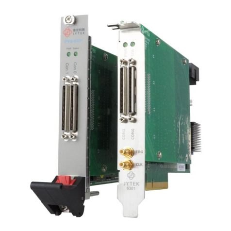
Table 14 SSI Connector Pin Assignment for PCIe-5111........................98
Table 15 Typical AI Accuracy ...............................................................100
Table 16 AI Bandwidth.........................................................................101
Table 17 Typical AO Accuracy..............................................................103
Figure 1 PCIe 5111 Front Panel...............................................................6
Figure 2 Sample Rate and Internal AD Conversion ...............................21
Figure 3 PCIe-5111 experiment .............................................................22
Figure 4 TB-68 Terminal Block...............................................................23
Figure 5 Continuous MultiChannel Paraments.......................................23
Figure 6 MultiChannel Continuous Acquisition.......................................24
Figure 7 Differential Mode for Grounding Signals ..................................26
Figure 8 Choose Differential in AI Terminal ...........................................27
Figure 9 RSE Mode for Floating Signals................................................28
Figure 10 NRSE Mode for Grounding Signals .......................................29
Figure 11 Choose NRSE In AI Terminal ................................................30
Figure 12 Immediate trigger Paraments.................................................31
Figure 13 Software trigger Paraments...................................................32
Figure 14 Software trigger Acquisition...................................................32
Figure 15 Rising Slope Trigger..............................................................34
Figure 16 Falling Slope Trigger..............................................................34
Figure 17 Hysteresis with Rising Slope Trigger .....................................35
Figure 18 Hysteresis with Falling Slope Trigger.....................................35
Figure 19 Entering Window Trigger .......................................................36
Figure 20 Leaving Window Trigger........................................................36
Figure 21 Analog Trigger Paraments.....................................................37
Figure 22 Waiting For Trigger................................................................37
Figure 23 Analog Trigger Acquisition.....................................................38
Figure 24 External Digital Trigger ..........................................................39
Figure 25 Digital Trigger Paraments......................................................39
Figure 26 Digital Trigger Acquisition......................................................40
Figure 27 Start Trigger ..........................................................................41
Figure 28 Reference Trigger..................................................................42
Figure 29 ReTrigger ..............................................................................42
Figure 30 Retrigger Paraments..............................................................43

V 1.0.4 JY5111 | jytek.com | 14
Figure 31 Retrigger In Start Trigger Mode .............................................44
Figure 32 Retrigger In Reference Trigger Mode ....................................44
Figure 33 Complete Retrigger Count.....................................................45
Figure 34 AI Continuous Paraments......................................................46
Figure 35 AO Finite Output Paraments..................................................46
Figure 36 AO Finite Signal.....................................................................47
Figure 37 AI Acquisition Signal..............................................................47
Figure 38 AI Continuous Paraments......................................................48
Figure 39 AO ContinuousNoWrapping Output Paraments.....................49
Figure 40 AO ContinuousNoWrapping Signal........................................50
Figure 41 AI Acquisition AO Sin Signal..................................................50
Figure 42 Update AO Square Signal .....................................................51
Figure 43 AI Acquisition AO Square Signal............................................51
Figure 44 AI Continuous Paraments......................................................52
Figure 45 AO Continuous Wrapping Paraments....................................53
Figure 46 AO Continuous Wrapping Signal ...........................................53
Figure 47 AI Acquisition AO Signal........................................................54
Figure 48 Single Digital Output..............................................................56
Figure 49 Single Digital Input.................................................................56
Figure 50 DI Continuous Paraments......................................................57
Figure 51 DO ContinuousNoWrapping Output.......................................58
Figure 52 DI Continuous Acquisition......................................................58
Figure 53 Counter Terminal...................................................................59
Figure 54 Counter Signal Wiring Instruction...........................................60
Figure 55 Simple Edge Counting in Single Mode...................................60
Figure 56 Buffered Edge Counting with Internal Sample Clock..............61
Figure 57 Simple Edge Counting with Implicit SampleClk......................61
Figure 58 Count Direction......................................................................62
Figure 59 EdgeCounting For Single Mode.............................................63
Figure 60 EdgeCounting For Finite Mode..............................................64
Figure 61 Counter Values For Internal Clock.........................................65
Figure 62 Counter Values For Implicit Clock..........................................65
Figure 63 Pulse Measurement in Single Mode ......................................67
Figure 64 Pulse Measurement with Internal SampleClk.........................68
Figure 65 Pulse Measurement with Implicit SampleClk .........................68
Figure 66 Pulse Measure For Single Mode............................................69
Figure 67 Pulse Measure Value For Single Mode..................................69
Figure 68 Pulse Measure For Finite Mode.............................................70
Figure 69 Pulse Measure Values For Finite Mode .................................71
Figure 70 Frequency Measurement with Internal Sample Clock ............72
Figure 71 Frequency Measure For Single Mode....................................73
Figure 72 Frequency Measure For Continuous Mode............................74
Figure 73 Frequency Measure Values...................................................75
Figure 74 Peroid Measure For Single Mode ..........................................76

V 1.0.4 JY5111 | jytek.com | 15
Figure 75 Peroid Measure For Continuous Mode ..................................77
Figure 76 Two-Edge Separation in Single Mode....................................78
Figure 77Two-Edge Separation with Internal Sample Clock..................79
Figure 78 Two-Edge Separation with Implicit Sample Clock..................79
Figure 79 Two-EdgeSeparation Measure For Single Mode ...................80
Figure 80 Two-EdgeSeparation Measure For Finite Mode.....................81
Figure 81 Quadrature Encoder x1 Mode................................................82
Figure 82 Quadrature Encoder x2 Mode................................................82
Figure 83 Quadrature Encoder x4 mode................................................83
Figure 84 Quadrature Encoder x1 with Sample Clock ...........................84
Figure 85 Quadrature Encoder x4 with Implicit Sample Clock ...............84
Figure 86 QuadEncoder For Single Mode .............................................85
Figure 87 QuadEncoder For Continuous Mode .....................................86
Figure 88 Two-Pulse Encoder in Single Mode.......................................87
Figure 89 Two-Pulse Encoder with Internal Sample Clock.....................87
Figure 90 Two-Pulse Encoder with Implicit Sample Clock .....................88
Figure 91 Two-PulseEncoder For Single Mode .....................................89
Figure 92 Two-PulseEncoder For Finite Mode.......................................90
Figure 93 Two-PulseEncoder For Continuous Mode .............................91
Figure 94 Single Pulse Output...............................................................92
Figure 95 Single Pulse Generation........................................................93
Figure 96 AI Acquisition Single Pulse....................................................93
Figure 97 Finite Pulse Output................................................................94
Figure 98 Finite Pulses Generation .......................................................95
Figure 99 AI Acquisition Finite Pulse .....................................................95
Figure 100 Continuous Pulse Output.....................................................96
Figure 101 Continuous Pulse Generation..............................................97
Figure 102 AI Acquisition Continuous Pulse..........................................98
Figure 103 SSI Connector in PCIe-5111................................................98
Figure 104 AI Measurement Error........................................................100
Figure 105 AI Error due to System Random Noise ..............................102
Figure 106 Common Mode Rejection Ratio.........................................102
Figure 107 Six Measurement Scenarios..............................................104
Figure 108 Using Resister to Reduce Common Mode Voltage Effect ..105

V 1.0.4 JY5111 | jytek.com | 16
3. Software
3.1. Supported Operating System
Windows 7/10, x64/x86, Linux. See additional information.
3.2. Programming Languages
Microsoft C#. See additional software information for other languages.
4. Order Information
PCIe-5111 (PN: JY2105110-02)
5. JYPEDIA
JYPEDIA is an excel file. It contains JYTEK product information, pricing, inventory
information, drivers, software, technical support, knowledge base etc. You can
register and download a JYPEDIA excel file from our web www.jytek.com. JYTEK
highly recommends you use this file to obtain information from JYTEK.
6. Additional Hardware Information
6.1. Basic DC AI Accuracy
The DAQ mode is the normal data acquisition mode commonly found in commercial
DAQ hardware. The basic AI DC accuracy Table 6 of the DAQ mode provides accuracy
entries when PCIe-5111 operates in the single channel mode and within the
indicated calibration temperature range. Please note that this accuracy is valid for
every single point regardless how many sample points you acquire.
Each entry in the basic accuracy table is a pair of gain and offset coefficients. Using these gain and
offset coefficients, your measurement accuracy can be calculated by following formula:
For example, at the 0.625 V range and 24 Hours column, if your measurement or

V 1.0.4 JY5111 | jytek.com | 17
reading is 0.02V, the accuracy of this measurement is:
The basic accuracy table also provides full-scale accuracy entries for a quick and
convenient look-up. For example, the full-scale accuracy for the 0.625 V range and
the 24-Hour calibration column is 348 µV.
6.2. Basic AO Accuracy
The AO output accuracy of PCIe-5111 when using the analog output function can be
calculated according to the corresponding parameters in the Table 8
Each entry in the basic accuracy table is a pair of gain and offset coefficients. Using
these gain and offset coefficients, your AO output basic accuracy is calculated by
following formula:
For example, at the 5V range and 24 Hours column, if your output is 2V, the accuracy
of this measurement is:
The basic accuracy table also provides full-scale accuracy entries for a quick and
convenient look-up. For example, the full-scale accuracy for the 5V range and the 24-
Hour calibration column is 285 V.
7. Additional Software Information
7.1. System Requirements
PCIe-5111 series boards can be used in a Windows or a Linux operating system.
Microsoft Windows: Windows 7 32/64 bit, Windows 10 32/64 bit.
Linux Kernel Versions: There are many Linux versions. It is not possible JYTEK can
support and test our devices under all different Linux versions. JYTEK supports the

V 1.0.4 JY5111 | jytek.com | 18
following Linux versions only.
Table 13 Supported Linux Versions
7.2. System Software
When using the PCIe-5111 series in the Window environment, you need to install the
following software from Microsoft website:
Microsoft Visual Studio Version 2015 or above,
.NET Framework version is 4.0 or above.
.NET Framework is coming with Windows 10. For Windows 7, please check .NET
Framework version and upgrade to 4.0 or later version.
Given the resources limitation, JYTEK only tested PCIe-5111 be with .NET Framework
4.0 with Microsoft Visual Studio 2015. JYTEK relies on Microsoft to maintain the
compatibility for the newer versions.
7.3. C# Programming Language
All JYTEK default programming language is Microsoft C#. This is Microsoft
recommended programming language in Microsoft Visual Studio and is particularly
suitable for the test and measurement applications. C# is also a cross platform
programming language.
7.4. PCIe-5111 Series Hardware Driver
After installing the required application development environment as described
Linux Version
Ubuntu LTS
16.04:4.4.0-21-generic(desktop/server)
16.04.6:4.15.0-45-generic(desktop) 4.4.0-142-generic(server)
18.04:4.15.0-20-generic(desktop) 4.15.0-91-generic(server)
18.04.4:5.3.0-28-generic (desktop) 4.15.0-91-generic(server)
Localized Chinese Version
中标麒麟桌面操作系统软件(兆芯版)V7.0(Build61): 3.10.0-862.9.1.nd7.zx.18.x86_64
中标麒麟高级服务器操作系统软件V7.0U6: 3.10.0-957.el7.x86_64

V 1.0.4 JY5111 | jytek.com | 19
above, you need to install the PCIe-5111 hardware driver.
JYTEK hardware driver has two parts: the shared common driver kernel software
(FirmDrive) and the specific hardware driver.
Common Driver Kernel Software (FirmDrive): FirmDrive is the JYTEK’s kernel software
for all hardware products of JYTEK instruments. You need to install the FirmDrive
software before using any other JYTEK hardware products. FirmDrive only needs to
be installed once. After that, you can install the specific hardware driver.
Specific Hardware Driver: Each JYTEK hardware has a C# specific hardware driver. This
driver provides rich and easy-to-use C# interfaces for users to operate various PCIe-
5111 function. JYTEK has standardized the ways which JYTEK and other vendor’s DAQ
boards are used by providing a consistent user interface, using the methods,
properties and enumerations in the object-oriented programming environment.
Once you get yourself familiar with how one JYTEK DAQ card works, you should be
able to know how to use all other DAQ hardware by using the same methods.
Note that this driver does not support cross-process, and if you are using more
than one function, it is best to operate in one process.
7.5. Install the SeeSharpTools from JYTEK
To efficiently and effectively use PCIe-5111 boards, you need to install a set of free C#
utilities, SeeSharpTools from JYTEK. The SeeSharpTools offers rich user interface
functions you will find convenient in developing your applications. They are also
needed to run the examples come with PCIe-5111 hardware. Please register and
download the latest SeeSharpTools from our website, www.jytek.com.
7.6. Running C# Programs in Linux
Most C# written programs in Windows can be run by MonoDevelop development
system in a Linux environment. You would develop your C# applications in Windows
using Microsoft Visual Studio. Once it is done, run this application in the
MonoDevelop environment. This is JYTEK recommended way to run your C#

V 1.0.4 JY5111 | jytek.com | 20
programs in a Linux environment.
If you want to use your own Linux development system other than MonoDevelop,
you can do it by using our Linux driver. However, JYTEK does not have the capability
to support the Linux applications. JYTEK completely relies upon Microsoft to maintain
the cross-platform compatibility between Windows and Linux using MonoDevelop.
8. Operating JY5111
This chapter provides the operation guides for PCIe-5111, including AI, AO, DI, DO,
Timer and programmable I/O interface, etc.
JYTEK provides extensive examples, on-line help and documentation to assist you to
operate the PCIe-5111 board. JYTEK strongly recommends you go through these
examples before writing your own application. In many cases, an example can also
be a good starting point for a user application.
8.1. Quick Start
After you have installed the driver software and the SeeSharpTools, you are ready to
use Microsoft Visual Studio C# to operate the PCIe-5111 products.
If you are already familiar with Microsoft Visual Studio C#, the quickest way to use
PCIe-5111 boards is to go through our extensive examples. We provide source code
of our examples. In many cases, you can modify the source code and start to write
your applications.
We also provide Learn by Example in the following sections. These examples will
help you navigate and learn how to use this PCIe-5111.
8.2. Data Acquisition Methods
PCIe-5100 uses a scanning method to acquire analog data, meaning there is only one
ADC chip on the device and all input channels share this ADC. In the scan acquisition
Table of contents
Other JYTEK Computer Hardware manuals

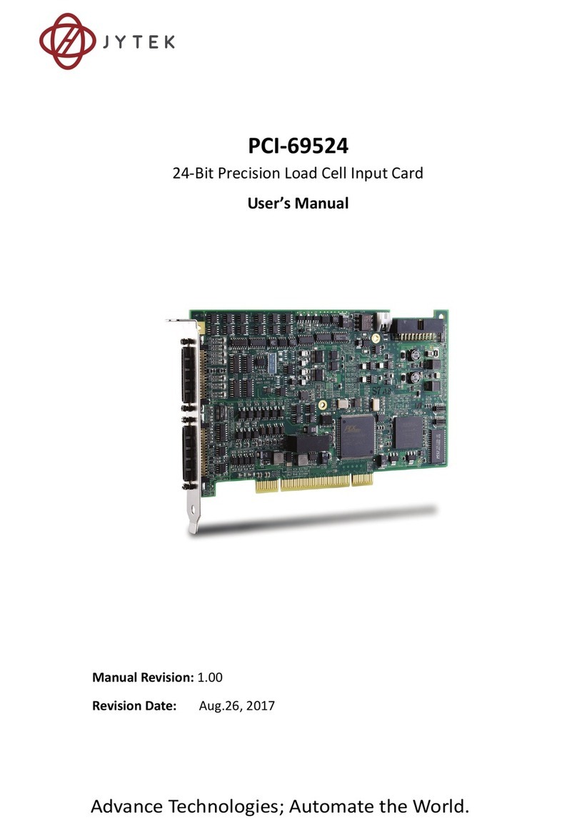
JYTEK
JYTEK NuDAQ PCI-69222 User manual

JYTEK
JYTEK PCIe-6301 Series User manual

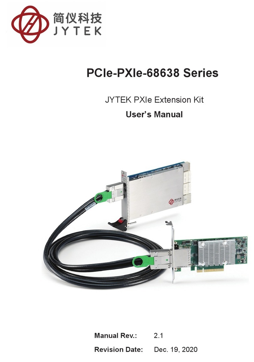
JYTEK
JYTEK PCIe-68560 User manual

JYTEK
JYTEK JY-5110 Series User manual

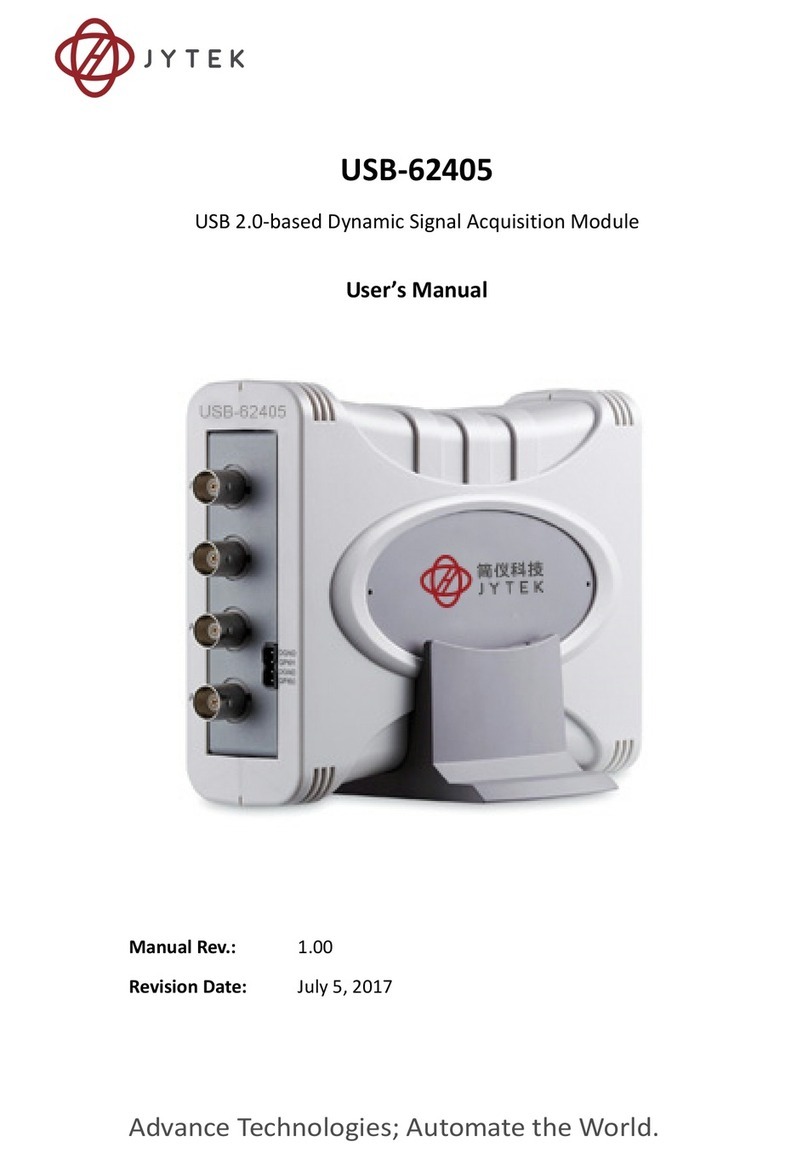
JYTEK
JYTEK USB-62405 User manual

JYTEK
JYTEK PCIe/PXIe-6301 Series User manual

JYTEK
JYTEK PCI-69524 User manual

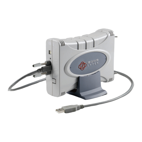
JYTEK
JYTEK USB-62401 User manual

JYTEK
JYTEK PCIe-68638 Series User manual

JYTEK
JYTEK 6743X Series User manual