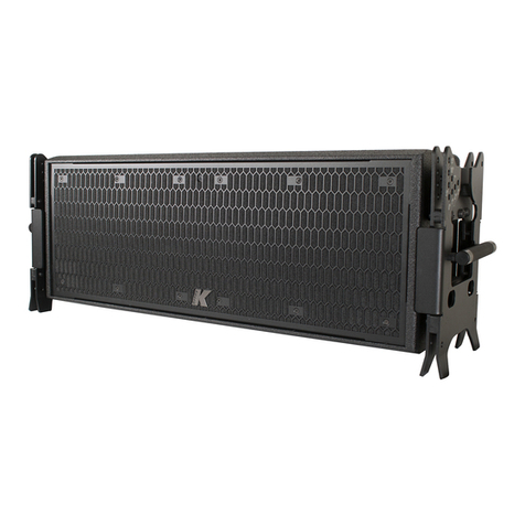
K-array Mugello-KH I User manual

USER GUIDE
•20221121•
Line array elements with
Electronic Beam Steering
Mugello-KH I

2
• Read these instructions.
• Keep these instructions.
• Heed all warnings.
• Follow all instructions.
• Do not use this apparatus near water.
• Clean only with dry cloth.
• Do not block any ventilation openings. Install in accordance with the
manufacturer’s instructions.
• Do not install near any heat sources such as radiators, heat registers, stoves, or
•
blades and a third grounding prong. The wide blade or the third prong is provided
•
• Protect the power cord from being walked on or pinched particularly at the plugs,
• Clean the product only with a soft and dry fabric. Never use liquid cleaning
products, as this may damage the products cosmetic surfaces.
•
manufacturer, or sold with the apparatus. When a cart is used, use
from tip-over.
• Unplug this apparatus during lightning storms or when unused for
long periods of time.
•
•
apparatus has been damaged in any way, such as power-supply cord or plug is
apparatus has been exposed to rain or moisture, does not operate normally, or
has been dropped.
•
only. To reduce the risk of electric shock, do not perform any servicing other than
•
General heed and warnings
This symbol alerts the user to the presence of recommendations
about the product’s use and maintenance.
triangle is intended to alert the user to the presence of uninsulated,
dangerous voltage within the product enclosure that may be of
magnitude to constitute a risk of electrical shock.
The exclamation point within an equilateral triangle is intended to alert
the user to the presence of important operating and maintenance
Operator’s manual; operating instructions
operating instructions and indicates that the operating instructions
should be considered when operating the device or control close to
where the symbol is placed.
For indoor use only
This electrical equipment is designed primarily for indoor use.
WEEE
Please dispose of this product at the end of its operational lifetime by
bringing it to your local collection point or recycling center for such
equipment.
Directive.
WARNING
Failure to follow these safety instructions could
the device or other property.
This apparatus is intended for professional use.

3
•
minimum.
• Use only speaker cables for connecting speakers to the speaker terminals.
connecting speakers in parallel. Connecting an impedance load outside the
• K-array cannot be held responsible for damage caused by improper use of the
loudspeakers.
•
This equipment has been tested and found to comply with the limits
for a Class B digital device, pursuant to part 15 of the FCC Rules. These
limits are designed to provide reasonable protection against harmful
interference in a residential installation. This equipment generates, uses and can
radiate radio frequency energy and, if not installed and used in accordance with the
instructions, may cause harmful interference to radio communications. However,
there is no guarantee that interference will not occur in a particular installation. If this
equipment does cause harmful interference to radio or television reception, which
to correct the interference by one or more of the following measures:
1. Reorient or relocate the receiving antenna.
2.
3.
the receiver is connected.
4.
This device complies with FCC radiation exposure limits set forth for an uncontrolled
environment. This equipment must be installed and operated in accordance with
to provide a separation distance of at least 20 cm from all persons.
1.
2. this device must accept any interference received, including interference that
may cause undesired operation.
K-array declares that this device is in compliance with applicable CE
This device complies with Industry Canada’s licence-exempt RSSs. Operation is
•
• this device must accept any interference, including interference that may cause
undesired operation of the device.
The device meets the exemption from the routine evaluation limits in section 2.5
of RSS 102 and compliance with RSS-102 RF exposure, users can obtain Canadian
information on RF exposure and compliance.
This equipment should be installed and operated with a minimum distance of 20

4
Index
6
Deafult Rigging Hardware 6
Rigging Accessories 7
7
7
7
Preparing the dolly 8
Wiring 9
9
Connectors 9
10
10
11
Status LED chart 11
12
13
13
14
Discovery 15
15
Rigging Procedures 16
16
Needed Equipment 16
17
19
19
Needed Equipment 19
19
19
20
21
Needed Equipment 21
21
Mechanical Drawing 22
22
22
23
23
24
25
Mugello-KH2I 25
Mugello-KH2PI 26
Mugello-KH3I 27
Mugello-KH3PI 28
Mugello-KH5I 29
Mugello-KH5PI 30
Thunder-KS3I 31
Thunder-KS3PI 32
Thunder-KS4I 33
Thunder-KS4PI 34

Mugello-KH I
User Guide
5
To ensure proper operation, please carefully read the owner’s
manuals and safety instruction before using the products.
Should you have any questions about your new
device please contact K-array customer service at
support@k-array.com or contact the
in your country.
The Mugello family comprises the KH2, KH3 and KH5 line array
elements. Incredibly compact and light, capable of combining
high power density with intelligibility and complete performance
control, the Mugello KH2, KH3 and KH5 are designed for quick
and easy installation, they are the ideal solution to reduce
transport and handling costs.
Enhanced performance and easy tuning are now managed
by the Integrated Electronic Brain – IEB – implemented into
micro electronics driven by the integrated operating system
user control over the system performance: Volumes, Signal
Routing, Presets as well as a complete USB player, are directly
manageable from the device via mobile app and dedicated
professional interface.

Mugello-KH I
User Guide
6
Unpacking
Each K-array product is built to the highest standard and
thoroughly inspected before leaving the factory.
Upon arrival, carefully inspect the shipping carton, then examine
notify the shipping company.
Powered loudspeakers: KH2 I, KH3 I, KH5 I
Deafult Rigging Hardware
Each Mugello-KH I line array element is equiped with a
elements in loudspeakers systems to be either suspended or
ground stacked.
The default rigging hardware comprises:
2x side plates with handles and holes for ball lock pins;
B. 6mm (
C. 2x rigging brackets.
Passive loudspeakers KH2P I, KH3P I, KH5P I
1x Passive Mugello-KHPI line array element with rigging hardware
A B C
CH1/CH2 INPUT
HF:1+ 1-
LF:2+ 2-
LINK LINK
HF:1+ 1-
LF:2+ 2-
CH1/CH2 PARALLELOUT
CH3/CH4 INPUT
CH3/CH4 PARALLELOUT
CH1
LINK
CH2
LINK
AES3
OUT
AES3
IN
1/2
3/4
KH2I
KH2PI
KH3I
KH3PI
KH5I
Rear panel
KH5PI Rear panel
Rear panel
KH5PI

Mugello-KH I
User Guide
7
Rigging Accessories
ground stack system accessories or the suspended system
accessories shall be added to the loudspeaker system.
Suspended Installation Accessories
Description Apply to
- WHITE
Bumper for
Bumper for
Fly bar for KH2I
step array
step array
Step array hardware for
to a KH3I or a KH5I (or
Ground Stack Installation Accessories
Description Apply to
Stacking hardware for
KH2I KH2 I
Stacking hardware for
KH3I and KH5 I
KH5I
KH3I
Accessories For Rigging The Subwoofers
Description Apply to
- WHITE
Bumper for
Bumper for
Rigging hardware for

Mugello-KH I
User Guide
Preparing the dolly
Prepare the stack of line array elements on top of the dolly.
using pin hole at 0°
facing inward.
MAX LOAD 366 kg
WEIGHT: 30 Kg
K-array surl via P.Romagnoli 17 - 50038 Scarperia e San Piero
Firenze - ITALIA
KH5-KH3 - K-HCDOLLY35
MAX LOAD 290 kg
WEIGHT: 28 Kg
K-array surl via P.Romagnoli 17 - 50038 Scarperia e San Piero
Firenze - ITALIA
KH2 - K-HCDOLLY2
0°
2°
3°
7°
5°
10°
15°
1°
FRONT

Mugello-KH I
User Guide
9
Wiring
Passive Array Elements - Audio Wiring
KH2P I, KH3P I and KH5P I
Once set on the dolly, the passive array elements KH2PI, KH3PI
to the number of units to be driven in parallel per stack.
is ready to be suspended or ground stacked.
KH2P I KH3P I KH5P I
Power handling
Bi-amp:
peak
peak
Bi-amp:
peak
peak
Quad-amp:
peak
peak
Nominal
Impedance
Connectors
Speaker input/parallel output
Rear panel
CH1/CH2 INPUT
HF: 1+ 1-
LF: 2+ 2-
LINK LINK
HF: 1+ 1-
LF: 2+ 2-
CH1/CH2 PARALLELOUT
CH3/CH4 INPUT
CH3/CH4 PARALLELOUT
Connectors
2+
1+
1-
2-
2+
1+
1-
2-
2+
1+
1-
2-
CH1/CH2INPUT
HF:1+1-
LF:2+2-
LINK LINK
HF:1+1-
LF:2+2-
CH1/CH2PARALLELOUT
CH3/CH4INPUT
CH3/CH4PARALLELOUT
CH1/CH2INPUT
HF:1+1-
LF:2+2-
LINK LINK
HF:1+1-
LF:2+2-
CH1/CH2PARALLELOUT
CH3/CH4INPUT
CH3/CH4PARALLELOUT
2+
1+
1-
2-
HF+
HF+
HF–
HF–
LF–
LF–
LF+
LF+
SpeakON NL4
connector
PC 4/ 4-ST-7,62
connector
2+
1+
1-
2-
HF+
HF+
HF–
HF–
LF–
LF–
LF+
LF+
SpeakON NL4
connector
PC 4/ 4-ST-7,62
connector
To the loudspeaker
LF
1+
1–
2+
2–
LF
HF
HF
KH2PI or KH3P I
up to 2x KH2PI
up to 2x KH3PI
up to 2x KH5PI
KH5PI
Improve system performance and reliability

Mugello-KH I
User Guide
10
power and signal distributor assembly
degned to drive KH2PI, KH3PI and
KH5PI passive array elements.
with wheels containing:
• the power panel with 3-phase
socket and switches;
•
•
• 1x Ethernet Switch 100Mbps;
•
• 2x RJ45 ports,
•
•
Rear panel:
1. SpeakON NL4 speaker output channels 3 & 4
2. SpeakON NL4 speaker output channels 1 & 2
3.
4.
5. QR Code for the K-array Connect app remote connection
6.
Active Array Elements: Audio Wiring
KH2 I, KH3 I and KH5 I
Once set on the dolly, the active array elements KH2I, KH3I
is ready to be suspended or ground stacked.
KA208 TOP KA208 MID KA208 BTM
A1 INPUT 1 INPUT 1 INPUT 1
A2 INPUT 2 INPUT 2 INPUT 2
A3 INPUT 3 INPUT 3 INPUT 3
A4 INPUT 4 INPUT 4 INPUT 4
CH1
LINK
CH2
LINK
AES3
OUT
AES3
IN
1/2
3/4
Cool
Heat
STC-1000
Set
S
32A
5P
P1
P2
P3
AUX
SW
VENT
C16 C16 C16 C16
AUX
L1
L2
L3
A2A1 P1 P2 P3
A4
A3
ETH
SW
IN OUT IN
IN OUT IN
02
01 01 03
02 04
OUT
OUT
01 03
02 04
01 03
02 04
A2A1 P1 P2 P3
A4
A3
ETH
SW
IN OUT IN
IN OUT IN
02
01 01 03
02 04
OUT
OUT
01 03
02 04
01 03
02 04
2
1
3
4
5
6
7
8
910
15
14
11
13
12
Fan

Mugello-KH I
User Guide
11
7.
9.
10.
11. Input signal LED monitor
12. Output signal LED monitor
13. System status LED
14. USB ports
15. RJ45 Ethernet port
The active array elements KH2I, KH3 I and KH5 I can be driven by
connection.
The Mugello-KH active array elements are Dante Ready
devices: Dante connectivity can be achieved by purchasing a
Controller version 4.5.0.9 or later.
KH2 I, KH3 I and KH5 I
power distribution system. Mugello-KH active line array units
voltage in the range 100 V - 230 V.
Wiring Europe
BLACK - GREY BLACK - RED - BLUE
BLUE GREY
Status LED chart
Color Mode Description
orange solid Booting: DSP software loading
Operating: high temperature warning
green solid System ready
red solid
blue solid Booting: Firmware loading
any
color blinking Fault detected
20
250
P S
E
20
250
PS
E
powerCON TRUE plug
L
N
Refer to professionals for selecting the proper
wire gauge according to local regulations.
powering the Mugello-KH active array units.

Mugello-KH I
User Guide
12
Use power cable with powerCon TRUE connector for powering
the Mugello-KH active array units:
1.
2. rotate the powerCon TRUE plug clockwise. Once properly
plugged and powered, the system status LED lights on.
can be used to daisy chain multiple Mugello-KH active array
elements. Refer to the following table for the maximum number
Device
AC 16 A line
AC 20A line
Mugello-KH2I
Mugello- KH3I
Mugello- KH5I 1
KH2 I KH3 I KH5 I
Power
Pink noise,
Pink noise,
Pink noise,
Distribute the loudspeaker loads across the three phases.
Even if more units can be powered by the same line, try to keep
the load balanced by connecting the loudspeakers evenly
among the three phase lines.
AC 16 A line
AC 16 A
4x KH2 I
4x KH3 I
2x KH5 I
click!
G N L1L2L3
Power
Power
Power
230V 3-Phase Wye
POWER DISTRO
powerCON TRUE plug
1 2
connected to a single power line and the

Mugello-KH I
User Guide
13
Distribute the loudspeaker loads across the three phases. Even
if more units can be powered by the same line, try to keep the
load balanced by connecting the loudspeakers evenly among
the three phase lines.
AC 20 A line
AC 20 A
2x KH2 I
2x KH3 I
1x KH5 I
Active Elements Driving Passive Elements:
Audio Wiring
array elementsfeaturepoweraudiooutputspeakONconnectors
designed to drive passive line array units of the same model.
CH KH2 I
Top
CH1
LINK
CH2
LINK
AES3
OUT
AES3
IN
1/2
3/4
1High
1+ 1–
1x KH2PI
2Low
2+ 2–
CH1
LINK
CH2
LINK
AES3
OUT
AES3
IN
1/2
3/4 3High
1+ 1–
2x KH2PI
4Low
2+ 2–
CH KH3 I
Top
CH1
LINK
CH2
LINK
AES3
OUT
AES3
IN
1/2
3/4
1High
1+ 1–
1x KH3PI
2Low
2+ 2–
CH1
LINK
CH2
LINK
AES3
OUT
AES3
IN
1/2
3/4 3High
1+ 1–
2x KH3PI
4Low
2+ 2–
CH KH5 I
Top
CH1
LINK
CH2
LINK
AES3
OUT
AES3
IN
1/2
3/4
1High
1+ 1–
1x KH5PI
2Low
2+ 2–
CH1
LINK
CH2
LINK
AES3
OUT
AES3
IN
1/2
3/4 3High
1+ 1–
4Low
2+ 2–
G N L1L2L3
Power
Power
Power
120V 3-Phase Wye
POWER DISTRO
connected to a single power line and the
CH1
LINK
CH2
LINK
AES3
OUT
AES3
IN
1/2
3/4
CH1
LINK
CH2
LINK
AES3
OUT
AES3
IN
1/2
3/4
CH1
LINK
CH2
LINK
AES3
OUT
AES3
IN
1/2
3/4
CH1
LINK
CH2
LINK
AES3
OUT
AES3
IN
1/2
3/4
CH1
LINK
CH2
LINK
AES3
OUT
AES3
IN
1/2
3/4
CH1/CH2INPUT
HF:1+1-
LF:2+2-
LINK LINK
HF:1+1-
LF:2+2-
CH1/CH2PARALLELOUT
CH3/CH4INPUT
CH3/CH4PARALLELOUT

Mugello-KH I
User Guide
14
K-framework3
The Mugello-KH active array elements can be remotely
controlled with the dedicated K-framework3 software available
The K-framework3 is the managing and
control software dedicated to professionals
and operators looking for a powerful tool for
designing and managing a large number of units
in demanding applications.
over the same Ethernet network.
when the devices are available, or import from scratch in the
on the network. In both cases, in order to discover and sync the
active devices, both the PC or Mac running the K-framework3
and the real units shall be properly connected to the same Local
The K-framework3 operates in three modes:
• 3D – Design a loudspeaker system for your venue in
simulations;
• SETUP – import from the 3D design the active
components into the workspace or build from scratch
control of the system;
•
system during the tuning session and control its
behavior in live events.
The network shall comprise:
•
•
•
•
a DHCP service is not available, each Mugello-KH active array
K-framework3
K-framework3
with DHCP server
Sidebar
Toolbar
Workspace
Menu bar
K-framework3 software

Mugello-KH I
User Guide
15
Grouping
The working paradigm in the K-framework3 is to group the input
and output channels of the active units on the workspace and
retained by the real units even once unplugged: if a real device
belongs to a group, the group is re-created on the workspace
Discovery
1.
the K-framework3 are properly connected to the same
network.
2. Power up the Mugello-KH units.
3. Launch the K-framework3.
4. Open the Network window and launch the discovery:
• For back compatibility with legacy Mugello-KH
communication is active: in case no legacy Mugello-KH
serial communication.
5. Once discovered, the real units are shown in the left
columns, following the order of their ID number; if the
workspace contains virtual devices of the same type you
can eventually modify the IDs in order to match the units
be in either directions: Workspace-to-Real or Real-to-
the single units separately
•
wrong ID, a dialog window appears where unique IDs can
be assigned to the units.
In Setup mode, set the Mugello-KH units local parameters
B.
groups as needed.
C.
units’ channels to the
groups.
D. Switch to Tuning mode.
E.
the tools available on the
groups (eq, delay, polarity,

Mugello-KH I
User Guide
16
Rigging Procedures
Suspended Array
Needed Equipment
Description Apply to
- WHITE
Bumper for
Bumper for
Fly bar for KH2I
step array
step array
Step array hardware for
to a KH3I or a KH5I (or
each use.
Always use properly rated rigging hardware.
K-array.
suspension points.
professionals.

Mugello-KH I
User Guide
17
KH2I, KH2PI,
KS3I, KS3PI
KH3I, KH3PI, KH5I, KH5PI,
KS4I, KS4PI
The line array is usually down-tilted from a high position
bumpers can be reversed fot up-tilting the line array.
Rigging Procedure: Splay Line Array
1. Set the bumper under the rigging position.
In orde to up-tilt the line array:
• take out the couple of quick-release pins and
• reverse the bumper;
• set the accessories as described in the following
pictures:
KH2 I KH3 I KH5 I KS3 I KS4 I
KH2P I KH3P I KH5P I KS3P I KS4P I
12 3 4 5 6 7 8 9 10111213141516171819
12 3 4 5 6 7 8 9 10111213141516171819
WEIGHT : 26.5 kg
MAX LOAD 775 kg (7:1)
MAX LOAD 1030 kg (7:1)
- Firenze ITALY
K-HCFLY2I
WEIGHT : 38 kg
MAX LOAD 960 kg (7:1)
MAX LOAD 1280 kg (7:1)
- Firenze ITALY
K-HCFLY35I
FRONT
FRONT
TOP
BOTTOM
top line array element
Down-tilting line array
Up-tilting line array
Single shackle lifting point Twin shackle lifting points

Mugello-KH I
User Guide
2.
3.
quick-release pins to secure the bumper to the top array
element.
4. Once the bumper is secured to the line array, remove the
the dolly.
5. Set the mechanical tilting of each line array element
according to the acoustic simulation made with the
K-framework3 software.
1918 17 16 15 14 13 12 11 10 9 8 7
654321
0°
2°
3°
7°
5°
10°
15°
1°
0°
2°
3°
7°
5°
10°
15°
1°
1918 17 16 15 14 13 12 11 10 9 8 7
654321
0°
2°
3°
7°
5°
10°
15°
1°
0°
2°
3°
7°
5°
10°
15°
1°
1918 17 16 15 14 13 12 11 10 9 8 7
654321
0°
2°
3°
7°
5°
10°
15°
1°
0°
2°
3°
7°
5°
10°
15°
1°
proceeding to the next step .
quick release pin
Down tilt the
array element
Insert the quick
release pin in the pin
hole according to the
desired tilting angle

Mugello-KH I
User Guide
19
Suspended Stand Alone Subwoofer
can be suspended as stand alone unit.
the unit and hang it to the rigging point.
Subwoofer Array
can be stacked on top of a line array of Mugello-KH loudspeakers
or used as basements for ground stacked array of Mugello-KH
units.
Needed Equipment
Description Apply to
KS3PI - WHITE
KS4PI - WHITE
Thunder-KS3I
Thunder-KS3PI
Mugello-KH2I
Mugello-KH2PI
Thunder-KS4I
Thunder-KS4PI
Mugello-KH3I
Mugello-KH3PI
Mugello-KH5I
Mugello-KH5PI
Rigging Procedure: Suspended Subwoofer Array
1.
2. Install the rigging frame at the subwoofer sides.
3.
suspension point.
4.
Use four quick-release pins to secure the bumper to the
subwoofer.
Remove the side bolts
1 2

Mugello-KH I
User Guide
20
5.
6.
angle of each unit.
7.
subwoofer.
Set the tilting angle of the Mugello-KH array element.
9. Proceed completing the line array with further units.
Rigging Procedure: Ground Stacked Subwoofer Array
1.
2. Install the rigging frame at the subwoofer sides.
3.
4.
subwoofer.
5. Set the orientation of the Mugello-KH bracket in order to
allow the unit to tilt upward or downward.
Set the unit tilting angle.
10°
10°
1°
2°
7°
3° 5°
5°
KH2ONLY
15°
KH2UPTILT KH2DOWN TILT
KH2DOWNTILTPIVOT POINT
15°
0° 0°
KH2UPTILTPIVOT POINT
KS3
10°
10°
1°
2°
7°
3° 5°
5°
KH2ONLY
15°
KH2UPTILT KH2DOWN TILT
KH2DOWNTILTPIVOT POINT 15°
0° 0°
KH2UPTILTPIVOT POINT
KS3
10°
10°
1°
2°
7°
3°
5°
5°
KH2ONLY
15°
KH2UPTILT KH2DOWN TILT
KH2DOWNTILTPIVOT POINT
15°
0° 0°
KH2UPTILTPIVOT POINT
KS3
10°
10°
1°
2°
7°
3° 5°
5°
KH2ONLY
15°
KH2UPTILT KH2DOWN TILT
KH2DOWNTILTPIVOT POINT 15°
0° 0°
KH2UPTILTPIVOT POINT
KS3
10°
10°
1°
2°
7°
3° 5°
5°
KH2ONLY
15°
KH2UPTILT KH2DOWN TILT
KH2DOWNTILTPIVOT POINT 15°
0° 0°
KH2UPTILTPIVOT POINT
KS3
10°
10°
1°
2°
7°
3° 5°
5°
KH2ONLY
15°
KH2UPTILT KH2DOWN TILT
KH2DOWNTILTPIVOT POINT 15°
0° 0°
KH2UPTILTPIVOT POINT
KS3
10°
10°
1°
2°
7°
3° 5°
5°
KH2ONLY
15°
KH2UPTILT KH2DOWN TILT
KH2DOWNTILTPIVOT POINT 15°
0° 0°
KH2UPTILTPIVOT POINT
KS3
10°
10°
1°
2°
7°
3° 5°
5°
KH2ONLY
15°
KH2UPTILT KH2DOWN TILT
KH2DOWNTILTPIVOT POINT
15°
0° 0°
KH2UPTILTPIVOT POINT
KS3
10°
10°
1°
2°
7°
3° 5°
5°
KH2ONLY
15°
KH2UPTILT KH2DOWN TILT
KH2DOWNTILTPIVOT POINT 15°
0° 0°
KH2UPTILTPIVOT POINT
KS3
10°
10°
1°
2°
7°
3°
5°
5°
KH2ONLY
15°
KH2UPTILT KH2DOWN TILT
KH2DOWNTILTPIVOT POINT
15°
0° 0°
KH2UPTILTPIVOT POINT
KS3
10°
10°
1°
2°
7°
3° 5°
5°
KH2ONLY
15°
KH2UPTILT KH2DOWN TILT
KH2DOWNTILTPIVOT POINT 15°
0° 0°
KH2UPTILTPIVOT POINT
KS3
10°
10°
1°
2°
7°
3° 5°
5°
KH2ONLY
15°
KH2UPTILT KH2DOWN TILT
KH2DOWNTILTPIVOT POINT 15°
0° 0°
KH2UPTILTPIVOT POINT
KS3
10°
10°
1°
2°
7°
3° 5°
5°
KH2ONLY
15°
KH2UPTILT KH2DOWN TILT
KH2DOWNTILTPIVOT POINT 15°
0° 0°
KH2UPTILTPIVOT POINT
KS3
10°
10°
1°
2°
7°
3° 5°
5°
KH2ONLY
15°
KH2UPTILT KH2DOWN TILT
KH2DOWNTILTPIVOT POINT 15°
0° 0°
KH2UPTILTPIVOT POINT
KS3
10°
10°
1°
2°
7°
3° 5°
5°
KH2ONLY
15°
KH2UPTILT KH2DOWN TILT
KH2DOWNTILTPIVOT POINT 15°
0° 0°
KH2UPTILTPIVOT POINT
KS3
0°
2° 3°
7°
5°
10°
15°
1°
10°
10°
1°
2°
7°
3° 5°
5°
KH2ONLY
15°
KH2UPTILT KH2DOWN TILT
KH2DOWNTILTPIVOT POINT 15°
0° 0°
KH2UPTILTPIVOT POINT
KS3
0°
2° 3°
7°
5°
10°
15°
1°
10°
10°
1°
2°
7°
3° 5°
5°
KH2ONLY
15°
KH2UPTILT KH2DOWN TILT
KH2DOWNTILTPIVOT POINT 15°
0° 0°
KH2UPTILTPIVOT POINT
KS3
10°
10°
1°
2°
7°
3° 5°
5°
KH2ONLY
15°
KH2UPTILT KH2DOWN TILT
KH2DOWNTILTPIVOT POINT 15°
0° 0°
KH2UPTILTPIVOT POINT
KS3
0°
2° 3°
7°
5°
10°
15°
1°
10°
10°
1°
2°
7°
3° 5°
5°
KH2ONLY
15°
KH2UPTILT KH2DOWN TILT
KH2DOWNTILTPIVOT POINT 15°
0° 0°
KH2UPTILTPIVOT POINT
KS3
0°
2° 3°
7°
5°
10°
15°
1°
10°
10°
1°
2°
7°
3° 5°
5°
KH2ONLY
15°
KH2UPTILT KH2DOWN TILT
KH2DOWNTILTPIVOT POINT 15°
0° 0°
KH2UPTILTPIVOT POINT
KS3
10°
10°
1°
2°
7°
3° 5°
5°
KH2ONLY
15°
KH2UPTILT KH2DOWN TILT
KH2DOWNTILTPIVOT POINT 15°
0° 0°
KH2UPTILTPIVOT POINT
KS3
0°
2° 3°
7°
5°
10°
15°
1°
10°
10°
1°
2°
7°
3° 5°
5°
KH2ONLY
15°
KH2UPTILT KH2DOWN TILT
KH2DOWNTILTPIVOT POINT 15°
0° 0°
KH2UPTILTPIVOT POINT
KS3
0°
2° 3°
7°
5°
10°
15°
1°
10°
10°
1°
2°
7°
3° 5°
5°
KH2ONLY
15°
KH2UPTILT KH2DOWN TILT
KH2DOWNTILTPIVOT POINT 15°
0° 0°
KH2UPTILTPIVOT POINT
KS3
10°
10°
1°
2°
7°
3° 5°
5°
KH2ONLY
15°
KH2UPTILT KH2DOWN TILT
KH2DOWNTILTPIVOT POINT 15°
0° 0°
KH2UPTILTPIVOT POINT
KS3
0°
2° 3°
7°
5°
10°
15°
1°
10°
10°
1°
2°
7°
3° 5°
5°
KH2ONLY
15°
KH2UPTILT KH2DOWN TILT
KH2DOWNTILTPIVOT POINT 15°
0° 0°
KH2UPTILTPIVOT POINT
KS3
0°
2° 3°
7°
5°
10°
15°
1°
10°
10°
1°
2°
7°
3° 5°
5°
KH2ONLY
15°
KH2UPTILT KH2DOWN TILT
KH2DOWNTILTPIVOT POINT 15°
0° 0°
KH2UPTILTPIVOT POINT
KS3
10°
10°
1°
2°
7°
3° 5°
5°
KH2ONLY
15°
KH2UPTILT KH2DOWN TILT
KH2DOWNTILTPIVOT POINT 15°
0° 0°
KH2UPTILTPIVOT POINT
KS3
0°
2° 3°
7°
5°
10°
15°
1°
10°
10°
1°
2°
7°
3° 5°
5°
KH2ONLY
15°
KH2UPTILT KH2DOWN TILT
KH2DOWNTILTPIVOT POINT 15°
0° 0°
KH2UPTILTPIVOT POINT
KS3
0°
2° 3°
7°
5°
10°
15°
1°
10°
10°
1°
2°
7°
3° 5°
5°
KH2ONLY
15°
KH2UPTILT KH2DOWN TILT
KH2DOWNTILTPIVOT POINT 15°
0° 0°
KH2UPTILTPIVOT POINT
KS3
0°
2° 3°
7°
5°
10°
15°
1°
10°
10°
1°
2°
7°
3° 5°
5°
KH2ONLY
15°
KH2UPTILT KH2DOWN TILT
KH2DOWNTILTPIVOT POINT 15°
0° 0°
KH2UPTILTPIVOT POINT
KS3
0°
2° 3°
7°
5°
10°
15°
1°
10°
10°
1°
2°
7°
3° 5°
5°
KH2ONLY
15°
KH2UPTILT KH2DOWN TILT
KH2DOWNTILTPIVOT POINT 15°
0° 0°
KH2UPTILTPIVOT POINT
KS3
0°
2° 3°
7°
5°
10°
15°
1°
10°
10°
1°
2°
7°
3° 5°
5°
KH2ONLY
15°
KH2UPTILT KH2DOWN TILT
KH2DOWNTILTPIVOT POINT 15°
0° 0°
KH2UPTILTPIVOT POINT
KS3
0°
2° 3°
7°
5°
10°
15°
1°
FRONT FRONT
Down-tilted unit Up-tilted unit
This manual suits for next models
6
Table of contents
Other K-array Speakers System manuals

K-array
K-array Ko40 User manual

K-array
K-array Vyper KV52 User manual

K-array
K-array Concert Series Quick start guide

K-array
K-array KN6 User manual

K-array
K-array Kobra KK200 User manual

K-array
K-array Redline KR100S User manual

K-array
K-array Pinnacle-KR II User manual

K-array
K-array Vyper KV50 User manual

K-array
K-array Redline KR100S User manual

K-array
K-array Kobra KK52 User manual