K-Line KL34000 User manual

KL34000
CooLant
ManageMent SySteM
operating inStruCtionS
315 Garden Avenue • Holland, MI 49424
www.klineind.com • 1-800-824-KLINE (5546) • cservice@klineind.com

introduCtion:
This manual contains information to help you to learn about the safe and proper use of
the KL34000 Coolant Management System. K-Line® Industries, Inc cannot anticipate all
conceivable or unique situations. The instructions and warnings included in this man-
ual are not necessarily all-inclusive. You must make sure all conditions and procedures
do not jeopardize your personal safety.
DISCLAIMER: All information, images, and specications contained in this manual are
based on the latest information available at the time of publication. K-Line® reserves
the right to make changes at any time without notifying any person or organization of
such revisions or changes. K-Line® is not liable for incidental or consequential damages
(including lost prots) in connection with the furnishing, performance, or use of this
material.
Safety preCautionS:
Before using the KL34000 Coolant Management System, read, understand, and
follow the safety precautions and operating instructions outlined in this manual.
This equipment must be operated by qualied personnel. The operator must be famil-
iar with vehicle cooling systems, coolants, and the dangers they present.
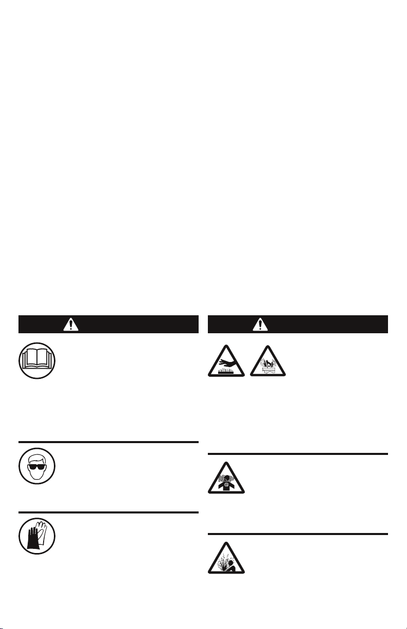
Personal Protection/
imPortant information
warning
To avoid personal injury, al-
ways wear protective gloves.
Hot antifreeze/coolant can burn
skin. If antifreeze/coolant comes in con-
tact with skin, thoroughly was area with
soap and water.
To avoid personal injury, care-
fully read and understand all
instructions before attempting
to operate any equipment or tools. Do
not operate or work on a machine unless
you read and understand the instructions
and warnings in this and all other appli-
cable manuals.
To avoid eye injury, always wear
protective glasses to guard
against possible ying particles
and/or debris. If contact with eyes occurs,
ush eyes with cold water for 30 minutes.
warning
To avoid inhaling mist or hot
vapors, use this product in a
well ventilated area. If inhaled,
move to fresh air and call a physician. If
swallowed, drink two glasses of water; in-
duce vomiting; and call a physician.
Hazard avoidance
Do not pressurize the vehicle
cooling system above its pres-
sure rating. Doing so may result
in cooling system failure and the release of
engine coolant.
To avoid personal in-
jury, allow engine to
cool completely. Hot
vehicle cooling systems are under pres-
sure. Opening a hot system can cause an
uncontrolled release of engine coolant.
Do not open the radiator cap, and do not
remove hoses from a hot system except as
directed in this manual.
2

objeCtive:
The KL34000 Coolant Management System uses two unique adapters and stan-
dard shop air to create regulated pressure that forces the coolant out of the
entire system, allowing for a pressure test and any necessary repairs to be made.
After this, a powerful vacuum is used to create negative pressure and draw the
coolant through the entire system from the bottom-up. This eliminates the pos-
sibility of air pockets forming in the EGR cooler.
generaL uSe and inStruCtionS:
Warning: Coolant may be HOT. Follow vehicle manufacturer’s
instructions for removing cooling system cap.
Caution: Safety glasses must be worn when using this tool.
ContentS:
Part # DesCriPtion Qty
KL34001 20 Gallon Tank and Cart Assembly 1
KL34008 Radiator Cap Adaptor Kit 1
KL34009 Pressure Regulator/Vacuum Handle Unit 1
KL34010 15’ Clear Hose Assembly 1
KL34000 inCLudeS:
To order optional accessories or replacement parts, contact K-Line Customer
Service at 1-800-824-KLINE (5546) or online at www.klineind.com.
3

drain proCedure:
1. Turn Tank valve to DRAIN.
2. Attach Tank hose to the quick
connect tting on the bottom of
the cooling system.
WARNING: Follow vehicle manufac-
turer’s instructions for removing the
cooling system cap.
3. Install the Cap Adapter
(KL34008) on the surge tank and
connect the Extension Hose to
the Schraeder tting.
4. Attach the Quick Connect Fit-
ting of the Extension Hose to the
Pressure Module.
5. Connect clean, dry shop air to
the 3-Way Air Valve and turn to
Drain.
6. When nished draining system,
close 3-Way Air Valve and make
necessary repairs.
before proCeeding:
1. A special male quick-connect tting will be needed to replace the
coolant drain petcock. Vehicles not built with this tting are easily
retrotted. Refer to TMC RP353 or ISO 16028 to ensure that you have
the proper tting. Please ensure that this tting is installed on the
vehicle before using the tool. If the truck is not equipped with the
tting, connect the Vacuum Module to the surge tank, follow steps
1- 4 under the Vacuum Procedure to draw partial vacuum and swap
the cooling system drain-cock with the Male Quick Connect Fitting.
2. Inspect the coolant level of the storage tank and engine.
3. If there is a known leak in the system a Gravity Drain must be per-
formed using Drain Procedure Steps 1 and 2. After necessary repairs
have been made, proceed to the Pressure Test Procedure on page 5.
4. Check the screen in the Y-Strainer on the Tank Valve for debris.
Image 1: Step 1
Image 2: Step 3
Image 3: Step 4
4

preSSure teSt proCedure:
1. Set Tank Valve to the CLOSED po-
sition.
2. Turn the 3-Way Air Valve to
DRAIN and monitor the Pressure
Module until gauge stabilizes.
3. Close 3-Way Air Valve. System is
now pressurized with air. Take
note of the gauge reading and
check for pressure decay.
ÂA constant pressure reading
indicates no leaks in the
system.
ÂA drop in pressure indicates a
leak in the system that must be
repaired.
4. If decay is evident, locate and re-
pair leak. When nished, repeat
the Pressure Test. If no decay is
detected, continue the proce-
dure.
5. Turn the Tank Valve to DRAIN to
vent air.
Image 4: Step 1
Image 6: Step 3
Image 5: Step 2
Image 7: Step 5
5

fiLL/vaCuuM proCedure:
1. Set the Tank Valve to the CLOSED
position
2. Disconnect the Extension Hose
from the Pressure Module and
attach to the Vacuum Module.
3. Turn the Blue Vent Valve to the
CLOSED position and attach
clean, dry shop air.
NOTE: Clear Exhaust Hose must be
directed to an appropriate location
because air and coolant mist will exit
hose.
4. Turn the 3-Way Air Valve to FILL
VEHICLE
5. Allow the Vacuum to draw 20”-
25”hg on the cooling system.
NOTE: Some engine manufacturers
do not permit this depth of vacuum
on the cooling system. Check with the
engine manufacturer before drawing
vacuum into the green zone.
6. Once Vacuum Module reaches
the green zone, set Tank Valve to
FILL position.
Image 10: Steps 4-5
Image 9: Step 3
Image 8: Step 1
Image 11: Step 6
6

7. Watch coolant level in Storage
Tank. When Tank is nearly empty
turn both the Tank Valve and the
3-Way Air Valve to the CLOSED
position.
IMPORTANT: Never allow the storage
tank to completely empty and thereby
allowing air to enter the cooling sys-
tem.
8. Open Blue Vent Valve to re-
lease vacuum. Disconnect the
KL34010 Hose from the KL34008
Cap adapter, and then remove
the KL34008 Cap Adapter.
9. Remove the Tank Hose and male
quick connect tting from the
bottom of the surge tank, and re-
place the coolant drain petcock.
Image 14: Step 8
This compleTes The operaTing insTrucTions
Image 12: Step 7
Image 13: Step 7
Add coolant and ll to proper
level. Replace surge tank cap.
10.
7

Copyright 2012 K-Line® Industries, Inc.
KL34001-200 Rev B 4/12
For product information or
to purchase replacement parts
CONTACT CUSTOMER SERVICE AT
1-800-824-K-LinE (5546)
Local (616) 396-3564
FAX 1-800-528-9138 or (616) 396-8974
http://klineind.com
Table of contents
Other K-Line Industrial Equipment manuals
Popular Industrial Equipment manuals by other brands

FMS
FMS RTM X42.Modbus Installation manual and operating instructions

Kentucky
Kentucky PD100 instruction manual

Eaton
Eaton AirFlex TLC 5004 Installation, operation and maintenance manual

Radijator
Radijator TKAN Integra Series instruction manual

Trotec
Trotec FS 200 operating manual

Vessel
Vessel IPC-A4 instruction manual

Nibe
Nibe ERS 10-400 Installer manual

Dynaset
Dynaset HEU 320-40E manual

BIO UV
BIO UV UV3205HO Installation and maintenance manual

Axminster Trade
Axminster Trade AT50LP Ultimate Edge Original instructions

Siemens
Siemens SIRIUS 3SB3863-4BC operating instructions

CommScope
CommScope FACT Installation instruction