Toro 9801 User manual

OPERATOR'S
MANUAL
FORM NO. 3318-402 GB Rev A
MODEL NO. 09801—60001 & OVER
® HYDROJECT®3000 AERATOR
©TheToro Company—1996

2
Foreward
The Hydroject 3000 is a water aerification device that penetrates and breaks up the soil with high-velocity water jets. This
machine operates with minimal disruption to the playing surface since there are no cores to remove after aerification.
After a quick rinse or irrigation cycle, the putting surface is ready for play.
The machine was designed to use water and NOT CHEMICALS. Since so many varieties of chemicals are used in the
Golf environment and since these chemicals react differently with Hydroject components, the Toro Company will not
accept responsibility for equipment or environmental damage caused by using chemicals. Using chemicals in your equip-
ment is done at your own risk!
The Hydroject 3000 releases a tremendous energy through the spray nozzles. DO NOT OPERATE THIS UNIT ON CON-
CRETE OR ASPHALT BECAUSE IT WILL PENETRATE THESE SURFACES.
Since this is a high-quality product, Toro is concerned about the future use of the machine and safety of the user.
Therefore, read this manual to familiarize yourself with safety, operation and maintenance instructions. Certain informa-
tion in this manual is emphasized. DANGER, WARNING and CAUTION identify personal safety-related information.
IMPORTANT identifies mechanical information demanding special attention. Be sure to read this directive because it
deals with the possibility of damaging a part or parts of the machine. NOTE identifies general information worthy of spe-
cial attention.
Service Manual
A service manual is available for the Hydroject 3000 Aerator. This publication provides information for trouble shooting,
testing, adjusting and repairing the machine. To order this publication, contact your local authorized Toro Distributor. Ask
for Form 91-764-SL, Hydroject 3000 service manua1l.
Table of Contents
SAFETY INSTRUCTIONS 3-4
SAFETY INSTRUCTIONS & DECALS .5
SPECIFICATIONS 6-7
FLUID RECOMMENDATIONS 8
IDENTIFICATION AND ORDERING 8
BEFORE OPERATING 10-12
Activate and Charge The battery 10
Check Engine Oil 10
Fill The fuel Tank With Gasoline 11
Check Gear Case Fluid Level 11
Check Pump Case Fluid Level 12
Check Tire Pressure 12
Check Accumulator Charge 12
CONTROLS 13
OPERATING INSTRUCTIONS 14-16
Operating Precautions 14
Starting/Stopping The engine 14
Training Period 14
Operating Procedure 14
Check Interlock System 16
Transport Operation 16
Inspection and Cleanup After Use 16
Pushing or Towing The machine 16
TROUBLE SHOOTING 18-20
MAINTENANCE 17
Servicing The pre- Filter 21
Replacing Main Water Filter 21
Changing Engine Oil and Filter 22
Servicing The Air Cleaner 22
Checking and Replacing The Spark Plug 24
Cleaning Cylinder Head Fins 24
Changing Gear Case Oil and Filter 25
Changing Pump Case Oil 25
Checking Hydraulic Lines and Hoses 25
Adjusting Roller Spray 27
Servicing Spray Wash Nozzles or Strainers 28
Battery Care 28
SEASONAL STORAGE 29
SERVICE INTERVAL CHART 30

3
Hazard control and accident prevention are dependent
upon the awareness, concern, and proper training of the
personnel involved in the operation, transport, mainte-
nance, and storage of the machine. Improper use or
maintenance of the machine can result in injury or
death. To reduce the potential for injury or death, com-
ply with the following safety instructions.
WARNING: Engine exhaust contains carbon monoxide
which is an odorless, deadly poison. Carbon monoxide
is also known to the State of California to cause birth
defects. Do not run the engine indoors or in an enclosed
area.
BEFORE OPERATING
1. Read and understand the contents of this Operator's
Manual before operating the machine. Become
familiar with all controls and know how to stop
quickly.
2. Never allow children to operate the machine. Do
not allow adults to operate the machine without
proper instruction. Only trained operators who have
read this manual should operate this machine.
3. Never operate the machine when under the influ-
ence of drugs or alcohol.
4. Before attempting to start the engine, engage the
parking brake.
5. Remove all debris or other objects that might inter-
fere with operation. Keep all bystanders away from
the work area.
6. Keep all shields and safety devices in place. If a
shield, safety device or decal is defective or dam-
aged, repair or replace it before resuming opera-
tion. Also tighten any loose nuts, bolts and screws
to assure the machine is in safe operating condition.
7. Do not operate the machine while wearing sandals,
tennis shoes, sneakers or shorts. Also, do not wear
loose fitting clothing which could get caught in
moving parts.Always wear long pants and substan-
tial shoes. Wearing safety glasses, safety shoes, ear
protection and a helmet is advisable and required
by some local ordinances and insurance regula-
tions.
8. Fill the fuel tank with gasoline before starting the
engine. Avoid spilling gasoline. Since gasoline is
flammable, handle it carefully.
A. Use an approved gasoline container.
B. Do not fill the tank while the engine is hot or
running.
C. Do not smoke while handling gasoline.
D. Fill the fuel tank outdoors and up to about 25
mm from top of the tank, not the filler neck.
E. Wipe up any spilled gasoline.
9. Check the interlock switches daily for proper oper-
ation. If a switch fails, replace it before operating
the machine. The interlock system is for your pro-
tection, so do not bypass it. Replace all interlock
switches every two years.
WHILE OPERATING
10. DON'T TAKE AN INJURY RISK! When a person
or pet appears unexpectedly in or near the WORK-
ING area, STOPAERATING.
11. Keep your hands and feet away from nozzle and
roller area. High-velocity water jets can penetrate
hands and feet. Penetration by the high-velocity
water jets can cause serious personal injury. If acci-
dental penetration occurs, seek medical attention
immediately.
12. Never use chemicals in the water supply system.
13. Do not operate the water injection system on con-
crete or asphalt because the water jets will perma-
nently damage these surfaces.
Safety Instructions

4
24. Be sure the machine is in safe operating condition
by keeping nuts, bolts and screws tight. Check all
bolts and nuts frequently to be sure they are tight-
ened to specification.
25. If the engine must be running to perform a mainte-
nance adjustment, keep your hands, feet, clothing
and other parts of your body away from any moving
parts.
26. Make sure all hydraulic line connectors are tight, and
all hydraulic hoses and lines are in good condition
before applying pressure to the system.
27. Keep your body and hands away from pin hole leaks
or nozzles that eject water or hydraulic fluid under
high pressure. Use paper or cardboard, not your
hands, to search for leaks. Hydraulic fluid or water
escaping under pressure can have sufficient force to
penetrate your skin and do serious damage. If either
of these fluids are ejected into your skin they must
be surgically removed within a few hours by a doc-
tor familiar with this form of injury or gangrene
may result.
28. Before disconnecting or performing any work on the
hydraulic oil system, all pressure in the system
must be relieved by stopping the engine and open-
ing the by-pass valve.
29. Make sure all water line connectors are tight, and all
hoses and lines are in good condition before apply-
ing pressure to the system.
30. Before disconnecting or performing any work on the
water system, all pressure in the system must be
relieved by stopping the engine and opening the
bleed valve. Opening the bleed valve allows any
trapped water to escape from the system and also
allows the accumulator piston to move to the bot-
tom of the accumulator cylinder.
31. The accumulator in this machine contains high-
pressure dry nitrogen. Accumulator servicing
requires special tools and precautions.
Accumulators do not contain user-serviceable com-
ponents. Improper accumulator servicing can cause
dismemberment or death. Do not attempt to disas-
semble a accumulator; have this work done by a
14. Start the engine with the parking brake engaged.
15. Do not run the engine in a confined area without ade-
quate ventilation. Exhaust fumes are hazardous and
could possibly be deadly.
16. Using the machine demands attention, and to prevent
loss of control:
A. Use only in daylight or when there is good artifi-
cial light.
B. Watch for holes or other hidden hazards.
C. Do not transport the machine close to a sand
trap, ditch, creek or other hazard.
17. If the machine starts to vibrate abnormally, shut off
the engine. Remove the wires from the spark plugs to
prevent the possibility of accidental starting. Check
the machine for damage and defective parts. Repair
any damage before restarting the engine and operat-
ing the machine.
18. Do not touch the engine or muffler while the engine is
running or soon after it is stopped. These areas could
be hot enough to cause a burn.
19. Before leaving the operator's position behind the han-
dle engage the parking brake.
20. When leaving the machine unattended, engage the
parking brake , shut OFF the engine and remove the
key from the ignition switch.
MAINTENANCE
21. Disconnect the wires from the spark plugs to prevent
accidental starting of the engine when servicing,
adjusting or storing the machine.
22. If the machine must be tipped to perform maintenance
or an adjustment, close the fuel shut-off valve, drain
gasoline from the fuel tank, oil from the crankcase
and remove the battery.
23. To reduce potential fire hazard, keep the engine free
of excessive grease, grass, leaves and accumulations
of dirt.

5
Authorized Toro Distributor.
32. Do not overspeed the engine by changing the governor
settings. To be sure of safety and accuracy, have an
Authorized T0R0 Distributor check maximum engine
speed with a tachometer.
33. The engine must be shut off before checking oil or
adding oil to the crankcase.
34. Allow the engine to cool before storing the machine in
any enclosure such as a garage or storage shed. Make
sure the fuel tank is empty if the machine is to be stored
longer than 30 days. Do not store the machine near any
open flame or where gasoline fumes may be ignited by
a spark. Always store gasoline in a safety-approved, red
metal container.
35. When storing or transporting the machine (trailering),
make sure the fuel shut-off valve is closed.
36. Perform only those maintenance instructions described
in this manual. If major repairs are ever needed or assis-
tance is desired, contact an Authorized Toro Distributor.
To ensure optimum performance and safety, always
purchase genuine TORO replacement parts and acces-
sories to keep the Toro all TORO. NEVER USE
WILL-FIT" REPLACEMENT PARTS AND ACCES-
SORIES MADE BY OTHER MANUFACTURERS.
Look for the TORO logo to assure genuineness. Using
unapproved replacement parts and accessories could
void the warranty of The Toro Company.

6
Symbol Glossary
SAFETY ALERT
SYMBOL GENERAL HAZARD
SAFETY ALERT CRUSHING OF
WHOLE BODY,
APPLIED FROM
ABOVE
CRUSHING OF
FINGERS OR HAND,
FORCE APPLIED
FROM SIDE
CUTTING OF
FINGERS OR HAND CUTTING OF FOOT CRUSHING OR
PUNCTURE OF FOOT,
CORING HEAD
WHOLE BODY ENTANGLEMENT,
IMPLEMENT INPUT DRIVE LINE FINGERS OR HAND
ENTANGLEMENT,
CHAIN DRIVE
THROWN OR FLYING
OBJECTS, WHOLE
BODY EXPOSURE
RUNOVER/BACKOVER,
GREENS AERATOR RUNOVER/BACKOVER,
HC 4000 AERATOR SECURE LIFTING CYLINDER WITH
LOCKING DEVICE BEFORE
GETTING IN HAZARDOUS AREA
INSERT SAFETY LOCK
BEFORE GETTING IN
HAZARDOUS AREA
STAY A SAFE DISTANCE FROM MACHINE,
GREENS AERATOR STAY A SAFE DISTANCE FROM MACHINE,
HC 4000 AERATOR
STAY CLEAR OF ARTICULATION
AREA WHILE ENFINE IS RUNNING,
GREENS AERATOR
DO NOT OPEN OR REMOVE
SAFETY SHIELDS WHILE
ENGINE IS RUNNING
SHUT OFF ENGINE & REMOVE
KEY BEFORE LEAVING OPERATOR
POSITION, GREENS AERATOR
CONSULT TECHNICAL MANUAL
FOR PROPER SERVICE
PROCEDURES
READ OPERATOR’S
MANUAL HEARING PROTECTION
MUST BE WORN BRAKE SYSTEM ENGAGE DISENGAGE

7
P
1 INCH (25mm)
P
ON/START OFF/STOP FAST SLOW CONTINUOUS
VARIABLE,
LINEAR
ENGINE START ENGINE STOP
PARK UNLEADED FUEL FUEL TANK FILL
LINE LOCK UNLOCK CORING HEAD
ALWAYS HAVE CORING HEAD
FULLY UP FOR TRANSPORT &
FULLY DOWN FOR CORING
TRACTION DRIVE MANUAL CHOCK WHEELS IN PARKED POSITION,
ALWAYS PARK ON LEVEL SURFACE,
FAIRWAY AERATOR
ALWAYS FORK FROM FRONT OR REAR
OF MACHINE, HC 4000 AERATOR LEVER OPERATION

8
Engine: Onan, 4-cycle, opposed-twin, air-cooled, 17.9
kW (24 hp) @ 3600 rpm, 983 cc displacement.
Electric start. Heavy-duty valve package. Extended
service air cleaner. 2.8 l oil capacity. Solid-state
ignition.
Clutches: Electromagnetic, dual-groove belt drive for
the water pump and driveshaft flange brake/clutch
for the main valve gearbox.
Electrical: 12-volt system with 20-amp circuit breaker
protection. Relays for all high-current switching.
Electronic controller and sensors for automatic
start-up and shut-down sequence of the water injec-
tion system. Group 28 battery with 525 cold-crank
amps.
Traction Drive: Closed-loop hydrostatic drive consist-
ing of Sundstrand variable volume pump and
Parker low-speed, high-torque wheel motor mount-
ed to steering fork. Hydraulic system contains 4.73
l with 25-micron suction line filter and gearbox
reservoir.
Tires/Wheels: Three, smooth-tread 2-ply, 18 x 9.50-8,
pneumatic tubeless, tires. Demountable drop-center
steel wheels with (4) lug nuts mounted to tapered
roller bearing hubs on the transport arms and brake
hub on the wheel motor. All are interchangeable.
Brake: Drum- and shoe-type parking brake mounted to
the wheel motor. Holds unit on a 30% grade.
Transport Lift: 12-volt Warner Electric linear screw
actuator with 15.24 cm stroke. Raises and lowers
lift arm/transport tires and activates hole spacing
control.
Fuel Capacity: 39.75 l gasoline.
Water Injection System:
Pre Filter—Spin-down type with washable cartridge
in clear plastic housing and plastic ball valve for
flushing.
Supply Filter—Replaceable cartridge in plastic
housing with an air bleed button.
Water Pressure Switch—Senses for water pressure
after the filter and turns on when pressure is over
138–193 kPa and turns off when pressure drops
below 48–90 kPa.
Pump—Pump is a Toro exclusive design (patent pend-
ing) with cast stainless steel head and 3 piston
plungers. Vee packing seals and Kevlar guides.
Forged crankshaft with plasma sprayed ceramic on
stainless steel plungers and cast iron connecting
rods. Nominal performance is 4 rpm @ 34,473 kPa
with 1400 rpm input.
Accumulator—Toro exclusive design with low charge
pressure sensor, nitrogen gas charged to a maximum
of 17,237 kPa.
Cam and Gearbox—Reduction gear drive for cam that
actuates the main water valve. Roller cam follower
rides on a cam specifically designed (patent pend-
ing) to control water injection at 5.3 cycles per sec-
ond (320 rpm) and store energy in the accumulator
between injections. Cast iron case also serves as 3.8
l hydraulic reservoir.
Valve—Cast stainless steel valve body functions as a
mounting base for the accumulator, gearbox and
manifold outlet. All high-pressure water flows in
and out through the valve body. Pressure-balanced
valve spool with floating (patent pending), hardened
stainless seat aligns during assembly. Bleed valve in
base allows for bleed-off of high pressure and drain
down for cold weather storage. Bolted flanges and
polyurethane O-rings mate all components to valve
body.
Rollers—Pivoting aluminum rollers uniformly smooth
the turf and provide protection from the nozzle dis-
charge.Adjustable flow (0–3 gpm) spray wash sys-
tem with 6 flood tip nozzles maintain clean rollers.
Pressure Relief Valve—Circle Seal Controls poppet-
type valve preset to 34,473 kPa with corrosion resis-
tant stainless and brass materials.
Specifications

9
Manifold and Nozzles—Extruded stainless steel mani-
fold with 11 flanged nozzle extensions containing
check valves and hardened stainless discharge ori-
fice. Check valves may be reversed in housing to
block unused nozzles.
Controls:
Engine Panel—Throttle, choke, spray wash control, hour
meter, water pressure gauge, spacing control lever,
key switch and circuit breaker reset button.
Steering Tiller Panel— Traction bail, water system
engage and disengage buttons, transport / aerate lift
toggle switch and parking brake with buzzer alarm.
Electronic Control Module—Solid state potted device
for sequencing start and stop of the water system.
Interlocks for water pressure, transport lift and trac-
tion neutral.
Ground Speed:
Aerating: 0–3.2 kmh (both directions)
Transport: 0–6.4 kmh (both directions)
Dimensions:
Length—244.4 cm
Wheelbase—135.1 cm
Width—160 cm
Height—119.9 cm
Weight—429.2 kg
Aeration Width: 83.8 cm with 11 nozzles on 7.6 cm cen-
ters.
Aeration Depth: 10.2–15.2 cm depending on turf condi-
tions and nozzle configuration.
Hole Pattern: Variable from 3.8–15.2 cm spacing in the
direction of travel, and 7.6–15.2 cm increments in width.
Depths and Nozzle Configurations: All nozzles are iden-
tified with numbers indicating the drill size of the orifice.
The standard configuration is 11 nozzles producing depths
of 10.2–15.2 cm depending on turf conditions. Blocked
nozzle locations are obtained by reversing the nozzle
check valve ball and spring. See nozzle size chart and
illustrations below:
IMPORTANT: Use only nozzle configurations shown
or damage to the machine may occur.
Aluminum Washer, Toro Part no. 80-6680 is required with
any nozzle change
Aluminum Washer, Toro Part no. 80-6680 is required with
any nozzle change
**Additional nozzles may be blocked to compensate for pump wear.
NOZZLE SIZE AND APPROXIMATE DEPTH CHART
Quantity of Nozzles
Part No. Drill Size Metric Size (mm) Open Blocked Depth
86-8130 #56 1.181 * * *
86-8131 #53 1.511 11 0 10.2–15.2 cm
86-8133 #46 2.057 6 5 15.2–20.3 cm

10
OPTIONAL STAGGERED SIZE NOZZLE CONFIGURATION
Quantity of Nozzles
Part No. Drill Size Metric Size (mm) Open Blocked Depth
86-8130 #56 1.181 6 and 0** 7.6–10.1 cm
86-8133 #46 2.057 5 0** 15.2–20.3 cm
Aluminum Washer, Toro Part no. 80-6680 is required with any nozzle change
**Additional nozzles may be blocked to compensate for pump wear.
Check Valve Ball
Check Valve Ball
Spring
Spring
OPEN NOZZLE CLOSED (BLOCKED) NOZZLE

2. Part number, description and quantity of parts
desired.
Note: Do not order by reference number if a parts
catalog is being used; use the part number.
11
Fuel—Unleaded regular gasoline recommended to minimize
engine intake valve and combustion chamber deposits.
Engine Oil—Service classificationAPI SF, SG, SF/CC or
SG/CC in a 30 weight viscosity grade.
Engine Oil Filter—Toro part no. 57-8530
Hydraulic Oil—Mobil DTE 26 or other interchangeable
equivalent. See chart below for equivalent oils.
Mobil DTE 26
Shell Tellus 68
Amoco Rykon Oil #68
Conoco Super Hydraulic Oil 68
Exxon Nuto H 68
Kendall Kenoil R&O 68
Pennzoil Penreco 68
Phillips Magnus A 68
Standard Energol HLP 68
Sun Sunvis 831 WR
Union Unax AW 68
Hydraulic Oil Filter—Toro part no. 67-8110
Water Pump Case Oil—Mobil DTE Extra Heavy or other
interchangeable ISO Grade 150 PE-700-A (Heavy
Inhibited Hydraulic & General Purpose) See following
chart for equivalent oils.
Mobil DTE EH (Extra Heavy)
Shell Turbo 150
Amoco American Ind. Oil 150
Chevron AW Machine Oil 150
Conoco Dectol R & O150
Exxon Terresstic 150
Kendall Ken-Tran 080
Pennzoil Penreco 150/AW150
Phillips Magnus Oil 150
Standard Energol HLP 150
Sun Sunvis 150
Union Unax RX 150/Turbine Oil 150
Valvoline ETC (R&O) #70
Water Supply—Recommend a source with 26.5–30.2 l
per minute. A minimum pressure of 207 kPa at the
machine is required for the pump to engage.
Maximum allowable pressure of 1,379 kPa.
Although irrigation water pumped from ponds or
effluent holding pools can be used, not all condi-
tions can be handled by the machine’s filtration sys-
tem. Additional or alternative filtration may be
required.
Water Filter Cartridge—Toro part no. 86-8630
DO NOT USE CHEMICALS—Concern for environ-
mental issues and corrosive affects on machine
components.
Fluid Specifications
Identification and Ordering
MODEL AND SERIAL NUMBERS
The HYDROJECT 3000 has two identification numbers: a
model number and a serial number. The two numbers are
stamped on a plate which is riveted to the frame. In any
correspondence concerning the HYDROJECT 3000, sup-
ply model and serial numbers to be sure that correct infor-
mation and replacement parts are obtained.
To order replacement parts from an authorized TORO
Distributor, supply the following information:
1. Model and serial numbers of the machine.

ACTIVATE AND CHARGETHE
BATTERY
1. Since the battery is not filled with electrolyte or activated,
bulk electrolyte with 1.260 specific gravity must be pur-
chased from a local battery supply outlet.
2. Release the hood latches and raise the hood.
3. Loosen the capscrew securing the battery clamp to the
machine and remove the battery. Remove the filler caps
from the battery and slowly fill each cell until electrolyte is
just above the plates.
4. Replace the filler caps and connect a 3- to 4-amp battery
charger to the battery posts. Charge the battery at a rate of 3
to 4 amperes for 4 to 8 hours.
5. When the battery is charged, disconnect the charger from
electrical outlet and battery posts.
6. Remove the filler caps. Slowly add electrolyte to each cell
until the level is up to fill ring. Install the filler caps.
IMPORTANT: Do not overfilI the battery. Electrolyte
will overflow onto other parts of the machine and severe
corrosion and deterioration will result.
7. Install the battery and secure it with the battery clamp.
8. Install the positive cable (rubber boot over end) to the posi-
tive (+) terminal and the negative cable (black) to the nega-
12
Figure 1
1. Battery
Before Operating
Electrolyte gases are explosive and can cause serious
injury to eyes, lungs and skin. Wear safety goggles
and rubber gloves when working with electrolyte or
the battery. Charge the battery in a well-ventilated
place so gasses produced while charging can dissipate.
Since the gasses are explosive, keep open flames and
electrical sparks away from the battery; do not smoke.
Nausea may result if the gasses are inhaled. Unplug
the charger from the electrical outlet before connecting
or disconnecting the charger’s leads.
WARNING

tive (-) terminal of the battery and secure with capscrews
and nuts. Slide the rubber boot over the positive terminal to
prevent possible short-out (Fig. 2).
9. Lower the hood and secure the latches.
CHECKTHE ENGINE OIL
The Onan engine is shipped with 3 quarts of oil in the crankcase;
however, the oil level must be checked before and after the
engine is first started.
1. Position the machine on a level surface.
2. Unscrew the dipstick and wipe it with a clean cloth. Screw
the dipstick into the filler neck and make sure it is seated
fully. Unscrew the dipstick out of the filler neck and check
the level of oil. If the oil level is low, add enough to raise
the level to the FULL mark on the dipstick.
Note: If the level of oil is at the ADD mark on the dipstick,
add 1 quart of oil to raise the oil level to FULL. Do not
overfill
3. Pour oil into the filler neck until the level is at the FULL
mark on the dipstick. The Onan engine uses any high-quali-
ty oil having theAmerican Petroleum Institute— APl—
“service classification” SF or SG. Recommended viscosity
(weight) of oil is SAE 30.
IMPORTANT: The Hydroject 3000 operates at very
high engine loads, so check the level of oil every 8 oper-
ating hours or daily. A new engine may consume some
oil until broken in. Initially, change the oil after the first
25 hours of operation; thereafter, under normal condi-
tions, change the oil and filter after every 100 hours of
operation. However, change oil more frequently when
the engine is operated in extremely dusty or dirty condi-
tions.
FILLTHE FUELTANKWITH
GASOLINE
THE TORO COMPANY STRONGLY RECOMMENDS THE
USE OF FRESH CLEAN, UNLEADED REGULAR GRADE
GASOLINE IN TORO GASOLINE POWERED PRODUCTS.
UNLEADED GASOLINE BURNS CLEANER, EXTENDS
ENGINE LIFE, AND PROMOTES GOOD STARTING BY
13
Figure 2
1. Dipstick

Figure 3
1. Fuel tank cap
REDUCING THE BUILD-UP OF COMBUSTION CHAMBER
DEPOSITS.
Note: Do not mix oil with gasoline. Never use methanol, gaso-
line containing methanol, gasohol, gasoline additives, premium
gasoline, or white gas because the engine/fuel system damage
could result.
1. Remove the cap from the fuel tank and fill the 37.85 l tank
to about 2.5 cm from the top of the tank, bottom of the filler
neck with unleaded gasoline. Install the fuel tank cap tight-
ly.
2. Wipe up gasoline that may have spilled to prevent a fire
hazard.
CHECK GEAR CASE FLUID LEVEL
The gear case, which acts as the reservoir for the hydraulic sys-
tem, is filled at the factory with approximately 3.8–4.7 l of
14
Because fuel is flammable, caution must be used when
storing or handling it. Do not fill the fuel tank while
the engine is running, hot or when the machine is in an
enclosed area. Vapors may build up and be ignited by
a spark or flame source many feet away. DO NOT
SMOKE while filling the fuel tank to prevent the pos-
sibility of an explosion. Always fill the fuel tank out-
side and wipe up any spilled fuel before starting the
engine. Use a funnel or spout to prevent spilling, and
fill the tank no higher than 2.5 cm (one inch) below
top of the tank, (bottom of the filler neck). DO NOT
OVER FILL.
Store fuel in a clean safety approved container and
keep the cap on the container. Keep fuel in a cool,
well-ventilated place; never in an enclosed area such
as a hot storage shed. To assure volatility, do not buy
more than a 30-day supply of gasoline, or a 6-month
supply of diesel fuel.
Since many children like the smell of gasoline, keep it
out of their reach because the fumes are explosive and
dangerous to inhale.
DANGER
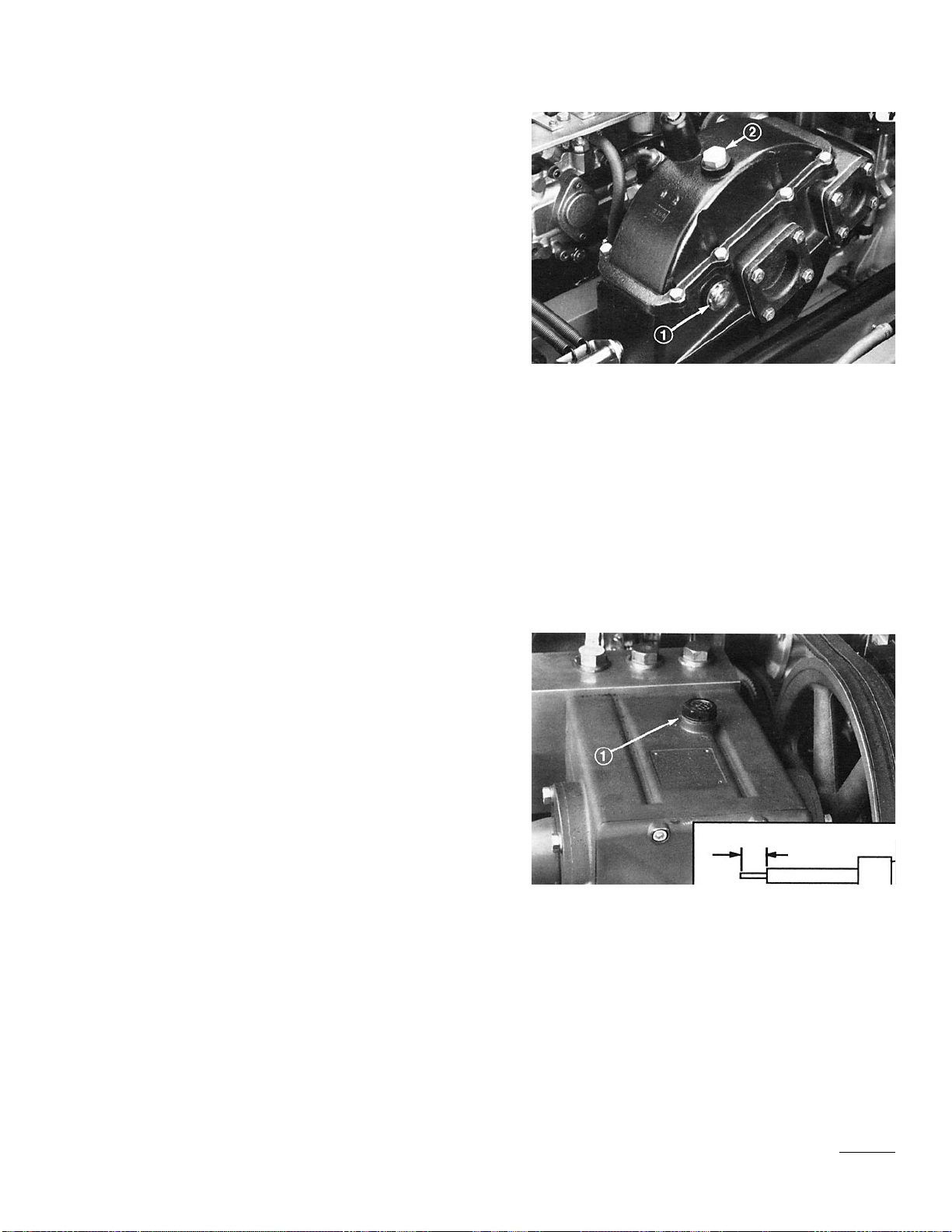
Mobil DTE 26 hydraulic oil. Check the level of hydraulic oil on
the sight gauge before the engine is first started and daily there-
after. Change the filter initially after 25 hours of operation,
thereafter change the oil and filter every 250 hours of operation.
The oil and filter must be changed immediately when any conta-
mination, sludge, water or condensation appears in the oil or on
sight gauge. Determine and correct oil contamination problem
before restarting the engine and operating the machine.
1. Position the machine on a level surface.
2. Release the hood latches and raise the hood.
3. Check the level of hydraulic oil on the sight gauge. Fluid
level should be up to the middle of gauge window.
4. If the fluid level is low, remove the filler cap and add
enough Mobil DTE 26 hydraulic oil or equivalent oil (refer
to fluid recommendation table) to bring oil up to the proper
level.
5. Lower the hood and secure the latches.
CHECK PUMP CASE FLUID LEVEL
The pump crank case is filled at the factory with 1.8 cl of Mobil
DTE Extra Heavy oil. Check the level of oil on the dipstick
before the engine is first started and daily thereafter. Change the
oil initially after 25 hours of operation, thereafter change every
250 hours of operation. The oil must be changed immediately
when any contamination, sludge, water or condensation appears
in oil. Determine and correct oil contamination problem before
restarting the engine and operating the machine.
1. Position the machine on a level surface.
2. Release the hood latches and raise the hood.
3. Remove the dipstick/filler cap and check the level of oil on
the dipstick. The fluid level should be up to the FULL
mark.
4. If the fluid level is low, add enough Mobil DTE Extra
Heavy oil or equivalent oil (refer to fluid recommendation
table) to bring the oil up to proper level. DO NOT OVER-
FILL.
5. Lower the hood and secure the latches.
15
Figure 4
1. sight gauge
2. Filler cap
Figure 5
1. Dipstick/Filler cap
Full

16
CHECKTIRE PRESSURE
Tires are over inflated for shipping. Make sure the front
and rear tires are inflated to 55–82 psi.
CHECKTHE ACCUMULATOR
CHARGE
Have the accumulator charge checked before and after
each operating season by an Authorized TORO
Distributor.
Charged accumulators contain high-pressure nitrogen.
Nitrogen is the only gas to use for accumulator char-
ing. Installing Improper gasses in an accumulator can
cause an explosion and death.
Charging requires special tools and precautions.
Charge accumulators in a well-ventilated area. Have
the accumulator checked and charged by an authorized
TORO distributor.
Wear eye protection. Keep your hands and face away
from the gas valve.
Slowly open the high-pressure water bleed valve
before servicing any component connected to the high-
pressure water system. Opening the high-pressure
bleed valve allows any trapped water to escape from
the system and also allows the accumulator platon to
move the bottom of the accumulator cylinder. Failure
to open the bleed valve before servicing high-pressure
water components can cause personal injury, dismem-
berment or death!
Charged accumulators cannot be shipped via air
freight.
WARNING
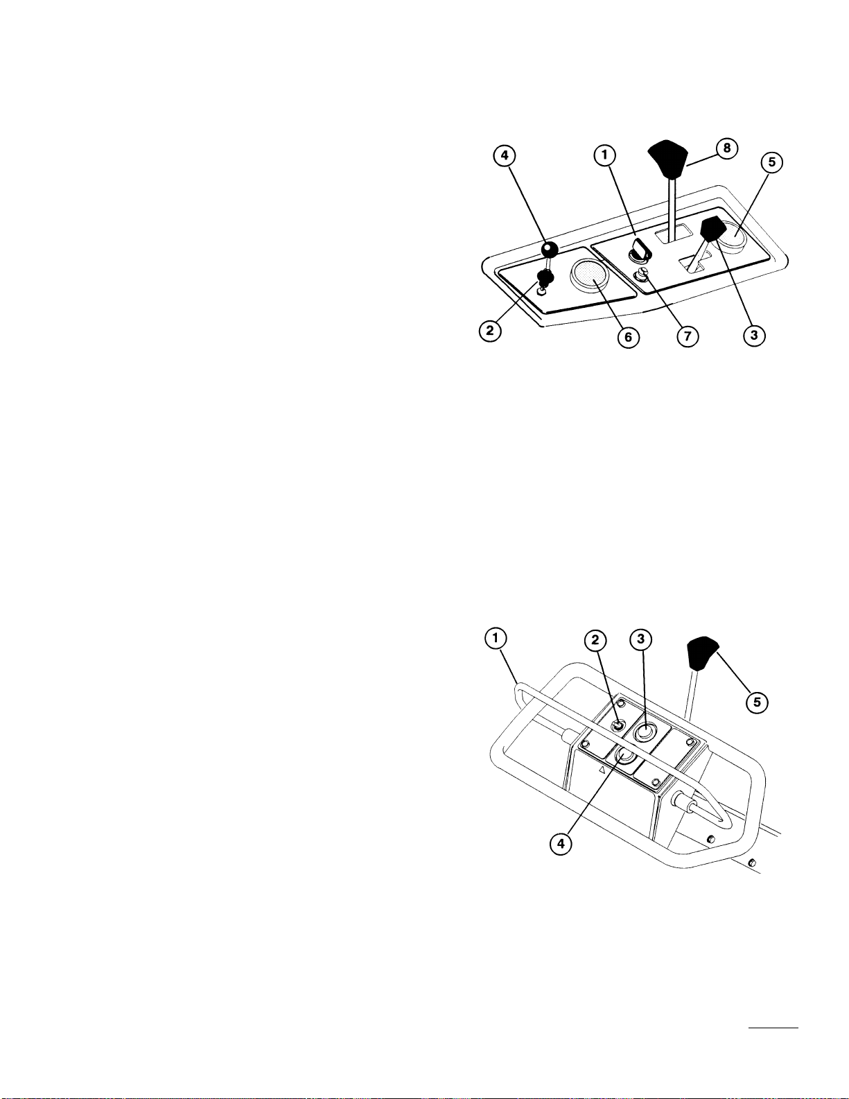
Ignition Switch (Fig. 6)—The ignition switch, which is used to
start and stop the engine, has three positions: OFF, ON and
START.
Choke (Fig. 6)—To start the engine, close the carburetor choke
by pulling the choke control outward to the FULL position.
After the engine starts, regulate the choke to keep the engine
running smoothly. As soon as possible, open the choke by push-
ing it inward to the OFF position.
Throttle (Fig. 6)—The throttle is used to regulate engine speed.
Moving the throttle forward increases engine speed— FAST;
rearward decreases engine speed—SLOW.
Spray Wash Control (Fig. 6)—Pull the handle upward to acti-
vate the roller spray wash system. Move the control knob up or
down to adjust spray rate to keep rollers free of debris.
Hour Meter (Fig. 6)—The hour meter registers accumulated
hours of engine operation. Use the hour meter to determine
intervals for service maintenance and lubrication.
Water Pressure Gauge (Fig. 6)—Registers supply water pres-
sure in the system. Also acts as a interlock switch preventing the
water pump from starting if water pressure is below 138–193
kPa or stopping the water pump if the water pressure drops
below 48–89.6 kPa. Check the gauge frequently to monitor the
water pressure.
Circuit Breaker Reset Button (Fig. 6)—a push button to reset
breaker, after correcting malfunctions in the electrical system.
The button also serves as a switch to interrupt power to the
relays.
Spacing Control Lever (Fig. 6)—Moving the control away
from handle increases the aerating ground speed and distance
between holes. Moving the control toward the handle decreases
aerating ground speed and distance between holes. The setting
will be overridden when the machine is shifted to the transport
position.
Traction Bail (Fig. 7)—Engages and regulates fore and aft trac-
tion operation of the machine. Releasing the bail stops traction
operation and will also stop water injection in 3 to 4 seconds,
unless the bail is engaged. Transport speed is regulated by the
distance the bail is moved.
Transport/Aerate Toggle Switch (Fig.7 )—Lowers the machine
17
Figure 6
1. Ignition switch
2. Choke
3. Throttle
4. Spray wash control
5. Hour meter
6. Water pressure gauge
7. Circuit breaker reset button
8. Spacing control lever
Figure 7
1. Traction Ball
2. Transport/Aerate toggle switch
3. Aeration engagement button
4. Aeration stop button
5. Parking brake
Controls

onto rollers to commence aeration. The switch will override
spacing control setting when it is moved to the transport posi-
tion.
Aeration Engagement Button (Fig. 7)—Depressing the button
starts water injection system only when the water pressure is
above 193 kPa and the rollers are on the ground.
Aeration Stop Button (Fig. 7)—This red button stops the water
injection system. The system continues for a few seconds after
button is pressed.
Parking Brake (Fig. 7)—Push the lever toward the machine to
engage the parking brake. A warning buzzer will sound if you
attempt to move the machine with the parking brake is engaged.
Fuel Shut-Off Valve—Located under the fuel tank. Close the
fuel shut-off valve when storing or transporting (trailering) the
machine.
18
Figure 7
1. Traction Ball
2. Transport/Aerate toggle switch
3. Aeration engagement button
4. Aeration stop button
5. Parking brake

OPERATING PRECAUTIONS
1. Before aerating, inspect the work area for debris and
determine the best direction and pattern in which to
operate the machine.
2. If the machine starts to vibrate abnormally, shut off the
engine. Remove the wires from the spark plugs to pre-
vent possible accidental starting. Check the machine for
damage and defective parts. Repair any damage before
restarting the engine and operating the machine.
3. Use only in daylight or when there is good artificial
light. Watch for holes or other hidden hazards. Do not
transport the machine close to a sand trap, ditch, creek
or other hazard.
4. Always raise the machine to the transport position
when parked on a green to prevent roller marks.
5. Do not operate the water injection system on concrete
or asphalt because water jets will permanently damage
these surfaces. Do not run over hoses because damage
will occur.
6. Do not operate the aerator with its roller or injection
system over the edge of anything that could be hit,
damaged or injured by high-velocity water blasts.
7. Water jets from the injection system should not damage
irrigation heads on one pass of the machine. Do not
allow multiple shots from the injection system to hit
irrigation heads as damage will occur.
8. Use a good, clean, quality water supply in the system.
If good quality water is not available, additional filtra-
tion equipment may be required. DO NOT USE
CHEMICALS IN THE WATER SYSTEM.
9. Do not allow the machine to be subject to freezing tem-
peratures without draining, because damage to the sys-
tem will occur.
19
STARTING / STOPPINGTHE
ENGINE
1. Make sure the wires are installed on the spark plugs
and the fuel shut-off valve is open.
2. Make sure the parking brake is engaged.
3. Pull the choke lever out to the FULL position and
move the throttle lever to the half-throttle position.
Note: When starting a warm the engine, the choke
may not be necessary, but HALF throttle is.
4. Insert the key into the ignition switch and turn it
clockwise to start the engine. Release the key when
the engine starts. Gradually return the choke lever
to the OFF position (lever all the way in) after the
engine starts and warms up.
IMPORTANT: To prevent overheating the
starter motor, do not engage the starter longer
than 30 seconds. After 30 seconds of continuous
cranking, wait 2 minutes before engaging the
starter motor again.
IMPORTANT: The engine is equipped with an
oil pressure interlock switch which interrupts
engine operation if there is not sufficient oil
pressure in the engine during starting or during
engine operation. The engine may start but will
not continue to run due to a lack of oil pressure.
5. To stop the engine, move the throttle control down-
ward to the SLOW position and turn the ignition
key to “OFF".
TRAINING PERIOD
Before aerating with the Hydroject 3000, it is suggested
that you find a clear area and practice starting and stop-
ping, raising and lowering the machine, turning, etc.
This training period will be beneficial in gaining confi-
Operation

dence in the performance of the Hydroject 3000.
OPERATING PROCEDURE
1. Make sure the wires are installed on the spark plugs and the
fuel shut-off valve is open.
2. Uncoil a garden hose making sure there are no kinks or
bends in the hose. Lay out the hose so there are no obstruc-
tions between the machine and the area to be aerated. Turn
on the water supply to purge any air from the hose. Turn off
the water.
3. Connect the hose adapter (Fig. 8) to the garden hose, then
connect the adapter to the quick coupler on the side of the
machine.
4. Turn on the water supply and check the water pressure. The
water pressure must be at least 207 kPa. If system pressure
is not 207 kPa, make sure your hose is not kinked or
obstructed, the water supply is turned on or if the water fil-
ter is plugged.
5. Reach under the fuel tank and press the bleed button on the
top of the water filter head (Fig. 9). Hold the bleed button
down until all air is purged from the filter and water comes
out the opening.
6. Reach under the hood and open the bleed valve on the main
valve at rear of the machine (Fig. 10). Bleed the system
until a steady flow of water comes from the outlet, then
close the valve.
7. If desired, the valve on the pre-filter (Fig. 11) may be
opened slightly (cracked) to provide continuous flushing
during machine operation.
8. Start the engine: refer to Starting/Stopping instructions.
Move the throttle to the FAST position and disengage the
parking brake.
9. Engage the traction bail and approach the area to be aerat-
ed. Make sure there are no obstructions between the aerator
and water supply.
10. Engage and hold the transport/aerate toggle switch to fully
lower the machine onto rollers, release the switch when
fully lowered, then press the engagement button to start
water injection.
20
Figure 8
1. Hose adapter
2. Quick coupler
Figure 9
1. Main water filter head
2. Bleed button
Figure 10
1. Main valve
2. Bleed valve
Other manuals for 9801
1
This manual suits for next models
1
Table of contents
Other Toro Tiller manuals

Toro
Toro 58601 User manual

Toro
Toro Hydroject 3000 User manual

Toro
Toro 09802 HydroJect 3010 User manual

Toro
Toro 23516 User manual

Toro
Toro 09802 HydroJect 3010 User manual

Toro
Toro 58602 User manual

Toro
Toro 09850 User manual

Toro
Toro 22542 User manual

Toro
Toro Soil Cultivator User manual

Toro
Toro 22445 User manual


