20
Dear customer,
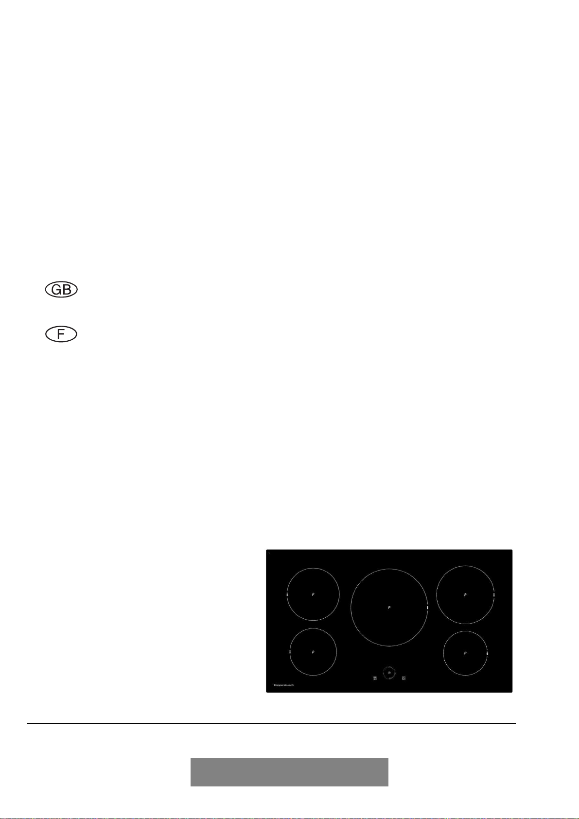
Thank you for having chosen a KÜPPERSBUSCH induction hob.
In order to install properly your appliance and to make the best use of it, please read this entire
instruction manual carefully.
SUMMARY
SAFETY........................................................................................................................................ 21
P
RECAUTIONS BEFORE USING
....................................................................................................... 21
U
SING THE APPLIANCE
................................................................................................................. 21
P
RECAUTIONS NOT TO DAMAGE THE APPLIANCE
............................................................................. 22
P
RECAUTIONS IN CASE OF APPLIANCE FAILURE
............................................................................... 22
O
THER PRECAUTIONS
.................................................................................................................. 22
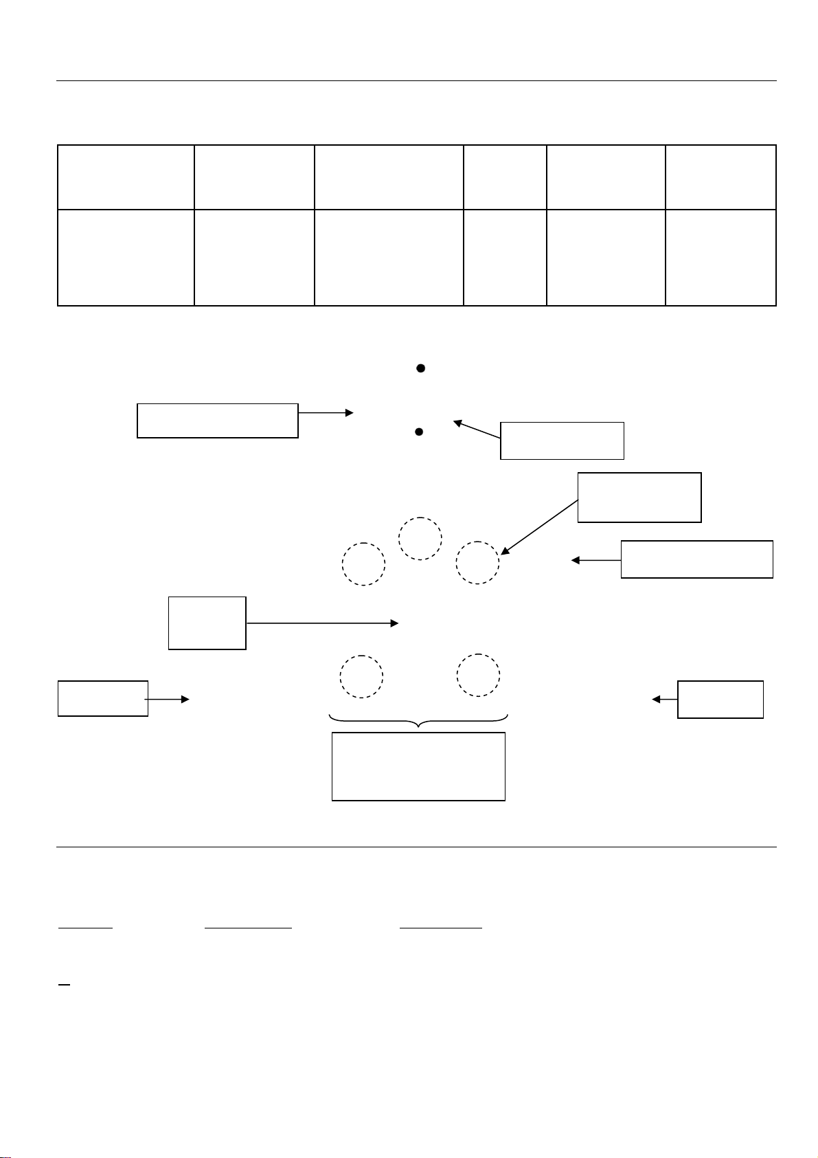
DESCRIPTION OF THE APPLIANCE.......................................................................................... 23
T
ECHNICAL CHARACTERISTICS
...................................................................................................... 23
C
ONTROL PANEL
......................................................................................................................... 23
USE OF THE APPLIANCE........................................................................................................... 23
D
ISPLAY
..................................................................................................................................... 23
V
ENTILATION
............................................................................................................................... 24
STARTING-UP AND APPLIANCE MANAGEMENT.................................................................... 24
B
EFORE THE FIRST USE
................................................................................................................ 24
I
NDUCTION PRINCIPLE
.................................................................................................................. 24
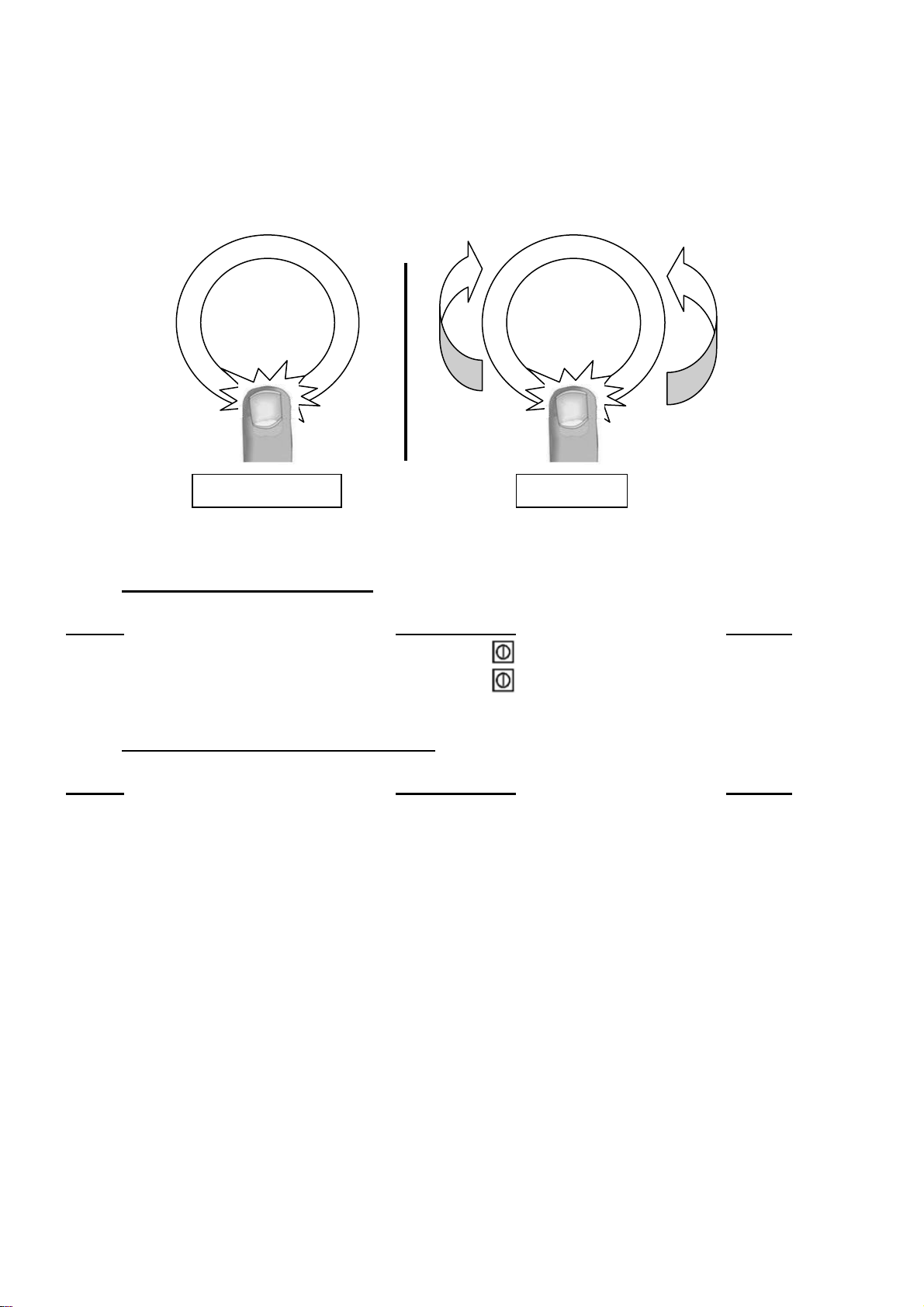
S
ENSITIVE TOUCH
........................................................................................................................ 24
“SLIDER”
ZONE
:
TO SET POWER AND TIMER VALUES
...................................................................... 25
S
TARTING
-
UP
.............................................................................................................................. 25
P
AN DETECTION
.......................................................................................................................... 26
R
ESIDUAL HEAT INDICATION
.......................................................................................................... 26
B
OOSTER FUNCTION
.................................................................................................................... 26
T
IMER
........................................................................................................................................ 27
A
UTOMATIC COOKING
.................................................................................................................. 28
S
TOP
&G
O FUNCTION
................................................................................................................... 28
M
EMORY FUNCTION
..................................................................................................................... 28
«
K
EEP WARM
»
F
UNCTION
.......................................................................................................... 29
C
ONTROL PANEL LOCKING
............................................................................................................ 29
O
PERATING TIME LIMITATION
........................................................................................................ 29
COOKING ADVICES.................................................................................................................... 30
P
AN QUALITY
.............................................................................................................................. 30
P
AN DIMENSION
........................................................................................................................... 30
E
XAMPLES OF COOKING POWER SETTING
....................................................................................... 31
MAINTENANCE AND CLEANING............................................................................................... 31
WHAT TO DO IN CASE OF A PROBLEM................................................................................... 32
ENVIRONMENT PRESERVATION .............................................................................................. 32
INSTALLATION INSTRUCTIONS................................................................................................ 33
ELECTRICAL CONNECTION...................................................................................................... 34