- 1
Please read and comply with
these original instructions prior
to the initial operation of your appliance and
store them for later use or subsequent own-
ers.
In the event of missing accessories or any
transport damage, please contact your
dealer.
–Warning and information plates on the
machine provide important directions
for safe operation.
–In addition to the information contained
in the operating instructions, all statuto-
ry safety and accident prevention regu-
lations must be observed.
Notes about the ingredients (REACH)
You will find current information about the
ingredients at:
www.kaercher.com/REACH
–This machine (attachment carrier) was
developed for use on greens, to take
care of landscaping and for winter ser-
vices.
–Different attachments (not included in
the scope of delivery) can be connected
to the front or the back of this machine.
Attachments that may jeopardise the
safety or stability of the machine, must
not be used.
–IMPORTANT! Before connecting at-
tachments that were not specifically in-
tended for this machine, please contact
your dealer to check how these attach-
ments should be connected and used.
This is essential for the safety of the
driver and the machine as well as for
possible warranty claims.
–This machine (attachment carrier) is
ready to operate when delivered. Prop-
er treatment and maintenance increase
the operational safety and product life
of the machine.
–The machine can also be used for tow-
ing (the hitch is already installed).
–Before working with this machine,
please read the operating instructions
carefully and become familiar with the
operating controls and the rest of the
equipment.
–The machine may not be modified.
–The machine may only be operated on
the surfaces approved by the company
or its authorised representatives.
–The machine with working equipment
must be checked to ensure that it is in
proper working order and is operating
safely prior to use. Otherwise, the appli-
ance must not be used.
–Only use accessories and spare parts
which have been approved by the man-
ufacturer. The exclusive use of original
accessories and original spare parts
ensures that the appliance can be oper-
ated safely and troublefree.
Contact the manufacturer if necessary.
–At the end of the operating instructions
you will find a selected list of spare
parts that are often required.
–For additional information about spare
parts, please go to the Service section
at www.kaercher.com.
–It is important to follow all safety instruc-
tions, rules and regulations applicable
for driving motor vehicles.
–The machine cannot be driven until you
are familiar with its operation and have
read and understood the operating in-
structions and safety notes.
–The appliance may only be used by per-
sons who have been instructed in han-
dling the appliance or have proven
qualification and expertise in operating
the appliance or have been explicitly
assigned the task of handling the appli-
ance.
–The operator must use the appliance
properly. He must consider the local
conditions and must pay attention to
third parties, in particular children, when
working with the appliance.
–The machine may not be used or stored
in hazardous areas. It is not allowed to
use the appliance in hazardous loca-
tions.
–The following applies in general: Keep
highly-flammable substances away
from the appliance (danger of explo-
sion/fire).
–All covers and safety equipment must
be properly installed.
–Only perform adjustment on the ma-
chine or the equipment while the motor
is shut off.
–Proceed with care in the area of the ar-
ticulating steering - risk of crushing!
–Lock the emergency brake and lower
the equipment to the ground (float posi-
tion) when you park the machine.
–Prior to beginning work, please check
all screwed connections for tight seat-
ing and all bolts for secure attachment.
Contents
General notes . . . . . . . . . . . EN . . .1
Environmental protection EN . . . 1
Proper use. . . . . . . . . . . EN . . . 1
Accessories and Spare
Parts . . . . . . . . . . . . . . . EN . . .1
Safety instructions . . . . . . . EN . . .1
Safety Devices . . . . . . . EN . . .2
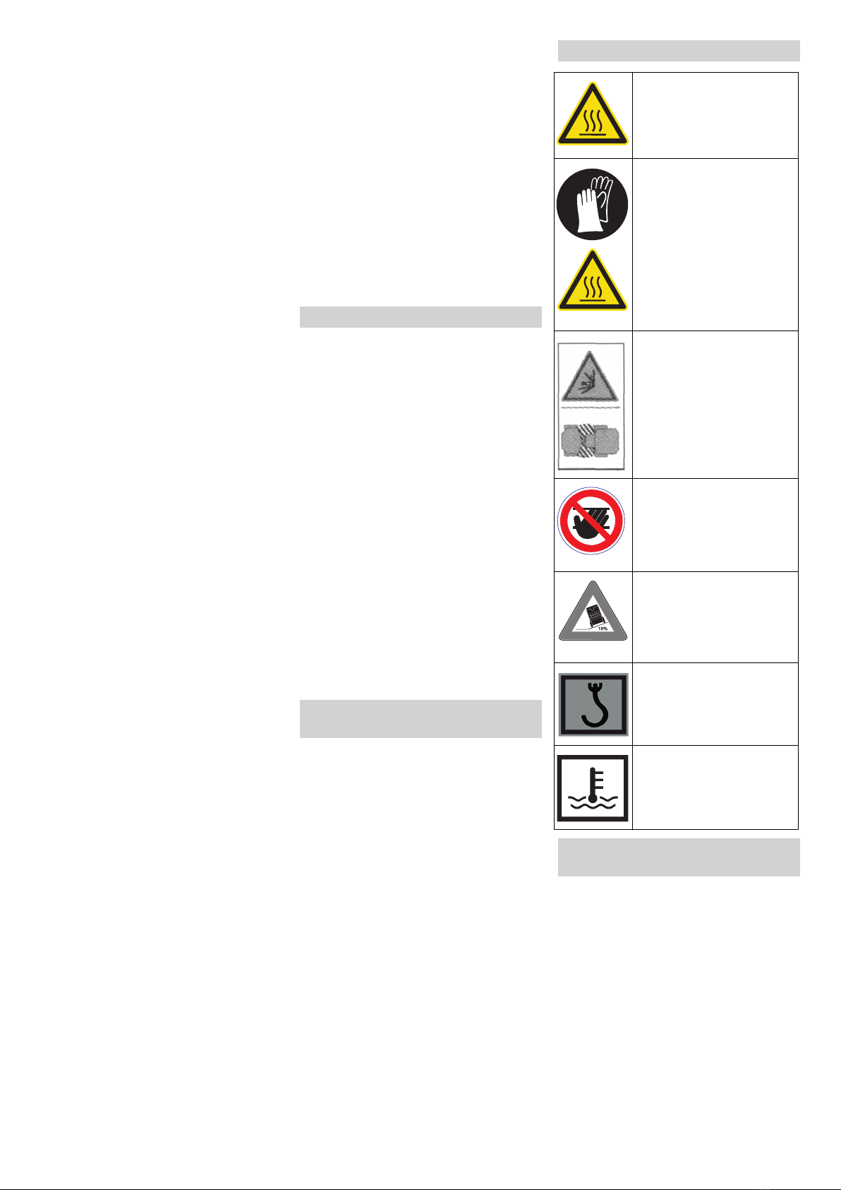
Symbols in the operating in-
structions. . . . . . . . . . . . EN . . .2
Symbols on the machine EN . . .2
The first 100 operating hours
(run-in time). . . . . . . . . . EN . . .2
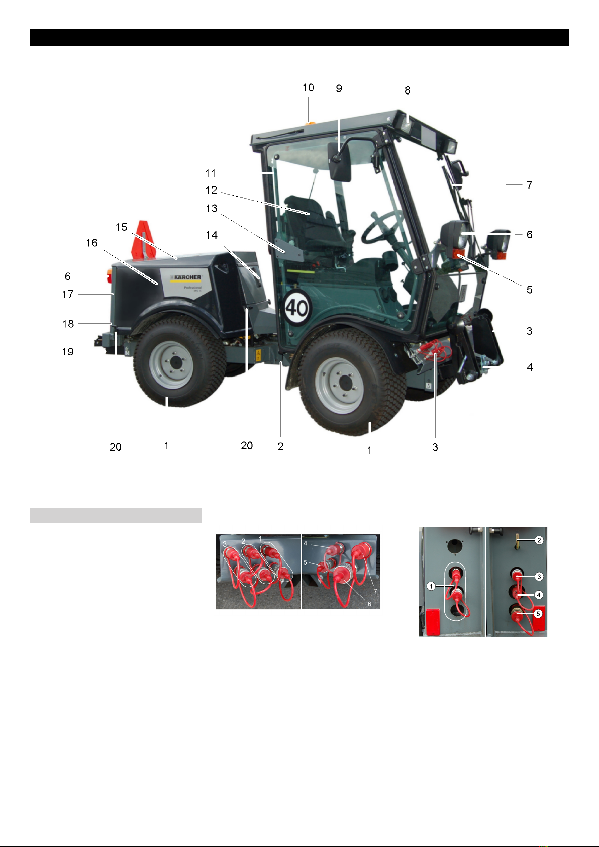
Overview of the appliance . EN . . .3
Exterior view of MIC 45 . EN . . . 3
Console . . . . . . . . . . . . . EN . . . 4
Operations . . . . . . . . . . . . . EN . . . 5
MIC 45 classic. . . . . . . . EN . . .5
MIC 45 classic / MIC 45 ad-
vanced. . . . . . . . . . . . . . EN . . . 5
MIC 45 advanced . . . . . EN . . .6
Before Startup. . . . . . . . . . . EN . . .7
Prior to initial start-up . . EN . . .7
Refuelling . . . . . . . . . . . EN . . .7
Windscreen washer system EN . . . 7
Adjusting driver's seat . . EN . . .7
Set the steering wheel posi-
tion . . . . . . . . . . . . . . . . EN . . .7
Prior to start/safety test . EN . . . 7
Operation . . . . . . . . . . . . . . EN . . . 8
Start the engine. . . . . . . EN . . .8
Driving . . . . . . . . . . . . . . EN . . . 8
Shutting down the appliance EN . . . 8
Attachments . . . . . . . . . . . . EN . . . 8
Towing hitch . . . . . . . . . EN . . .9
Storage . . . . . . . . . . . . . . . . EN . . .9
Maintenance and care . . . . EN . . . 9
Maintenance schedule . EN . . .9
Maintenance Works . . . EN . . .9
Adjustment tasks. . . . . . EN . .12
Cleaning tasks. . . . . . . . EN . . 12
Replacement tasks . . . . EN . . 12
Troubleshooting . . . . . . . . . EN . . 13
Faults with display. . . . . EN . .13
Faults without display . . EN . .13
Towing . . . . . . . . . . . . . . EN . . 13
Specifications . . . . . . . . . . . EN . .14
Warranty . . . . . . . . . . . . . . . EN . .15
Spare parts . . . . . . . . . . . . . EN . .15
General notes
Environmental protection
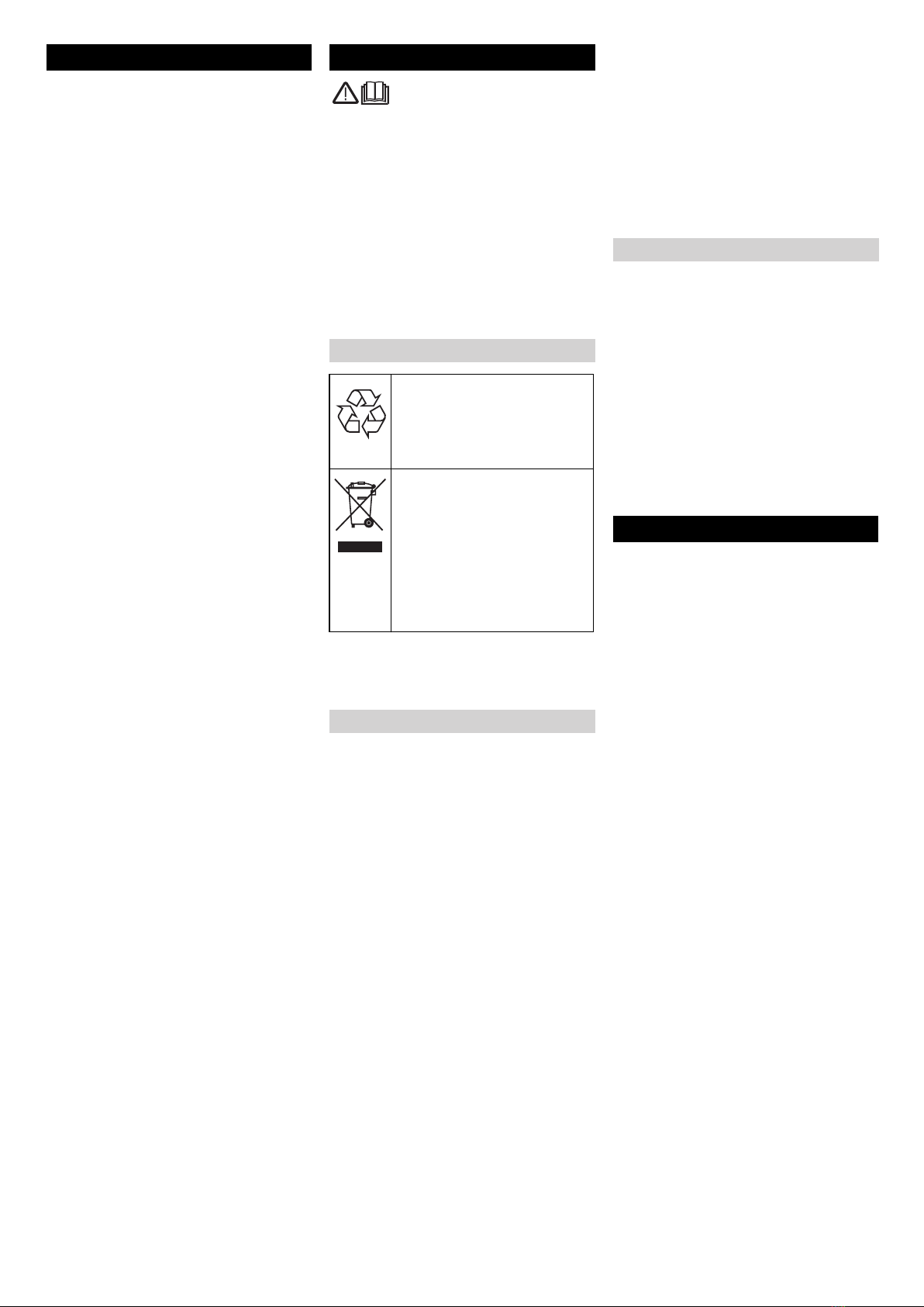
The packaging material can be
recycled. Please do not throw
the packaging material into
household waste; please send
it for recycling.
Old appliances contain valua-
ble materials that can be recy-
cled; these should be sent for
recycling. Batteries, oil, and
similar substances must not
enter the environment. Please
dispose of your old appliances
using appropriate collection
systems.
Proper use
Accessories and Spare Parts
Safety instructions
3EN