manuals.online logo
Brands
  1. Home
  2. •
  3. Brands
  4. •
  5. Kadee
  6. •
  7. Toy
  8. •
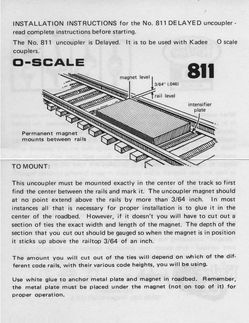
  9. Kadee 102 User manual

Kadee 102 User manual

#102
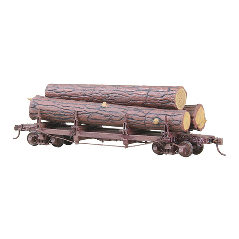
42 ft. SKELETON
LOG FLAT
In opening the parts package and handling the contents, use great care
to avoid loss or damage of the delicate pieces. The Instruction sheet
should be read thoroughly first, then Individual parts examined and
related to construction notes and Illustrations to better acquaint oneself
with all components and their proper placement on the model, as well as
relationship with each other.
Small amounts of light flashing may be encountered on castings and in most
Instances this can be removed with a knife blade, or a file. Note particularly,
openings on the underside of the log bunks, these may be closed off with
paper-thin flash that can be poked away with a sharp probe. Also one
opening will be found near the end of each bunk side, through which stake
chains must pass, these and the stakes as well may require cleaning out.
The dirt trap and its piping must be detached from the air tank casting
and relocated at right angles to Its original position as shown In Fig. 6.
Because this is a delicate casting, It Is suggested the part be detached
before an attempt Is made to remove flash from the dirt trap itself. Note,
the trap and piping does not fasten to the triple valve again until later
during the brake rigging assembly. The brake wheel comes attached to
a casting sprue which will serve as a handle while scraping away flash
from the outer rim area.
When the wheels clean, the sprue piece can be removed as Indicated In
Fig. 1. During this operation be extremely careful to grip the wheel properly
with pliers jaws while gently applying finger pressure In an upward and
downward motion on the sprue, otherwise It Is possible to break away a
portion of the wheel rim.
K-2 BRAKE SYSTEM:
Installation of the brake system is next and since the die cast body Is pre-
cast to accept all component parts, everything will go together with little
difficulty. One should note however, the two end castings are not identical,
one has a mounting plate to accommodate the brake wheel while the other
does not. Before proceeding further carefully remove all flash from both
end castings and center sills. The casting supporting the brake wheel fits
at the “B” end, thus correctly placing it In a position to accept the brake
chain from the rod affixed to brake lever “C” (Fig. 6). A few moments spent
studying Figs. 7 and 17 should make this clear. The exploded assembly
view (Fig. 7) shows all brake components clearly identified by letter to relate
to the following Instructions. Begin by placing air tank “A” and lever “C” on
the car body at one time. Cement, with Super glue®or Its equivalent, their
mounting studs Into the proper holes in the car body and at the same time,
cement the correct clevis projection of lever “C” into the end of the air tank.
If you fit these parts together one time on a trial basis without cement, you
will gain a much better idea of how to go about the operation. Next, lever
“D” Is placed, the two mounting studs on Its bracket to be entered into the
holes of the car body and secured with cement. At the same time this part
is being positioned, insert rod “F” into the correct clevis openings of lever
“C” and “D”. Using cement to form a bond.
The dirt trap (E) has been briefly mentioned above, note in Fig. 6. How it
is to be detached from its original position as It comes joined to the trio
pie valve at one end of the air tank. It is to be swung around to form a right
angle with the air tank as shown in Fig. 6. Note also, air line pipe “J” must
pass through the opening of the “tee” on the end of the dirt trap assembly
“E”. Since pipe “J” has been pre-bent, it will be necessary, using pliers,
to reduce the angle of the sharp bend at one end sufficient to allow It to
pass through the dirt trap pipe “tee”. When this has been done, restore
this bend in pipe “J” to its former angle for installation on the car. Slide dirt
trap assembly along pipe “J” so it is correctly positioned to cement the free
end of piping into the opening of elbow on the triple valve mounted atop
one end of air tank “A” (see Figs. 6 & 7).
Next, install one of the rods marked “H” by inserting the straight end into
the opening of outer clevis on long end of lever “C” and cement it there.
The bent end of this rod cements into car body. Remaining rod “H” cements
at the other end of the car, its straight end cementing into the opening of
clevis at outer end of lever “D”. Brake rod “G” will be Installed later when It
Is possible to pass it through the log bunk where it belongs. Three staples
designated “ST” fit into pre-cast holes as they are placed, two over lever
“C” and one over lever “D”, then cement into holes.
Now before proceeding further, flatten the head of the short 1/2” common
pin with a pair of pliers. Thread it through the end link of a 5/8” piece of
chain as shown In Fig. 2. Next push pin all the way into hole on the inside
and out through the brake ratchet. Put brake wheel on exposed pin end
and cut off pin leaving about 1/16” protruding beyond brake wheel. With
pliers, pinch pin as close to brake wheel as possible to flare it, cut off just
enough of the flat so the wheel will not come off. See Fig. 2 and Fig. 3.
Assemble the end castings onto the center sill by sliding them together
and tilting them up and then down so round end casting bosses fit into
end holes of center sill. This must be done before any of the couplers and
draft gear are Installed. See Fig. 8.
COUPLERS:
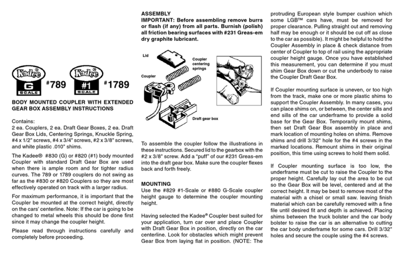
Make sure the coupler pocket is clear of any flash. Apply a little Kadee®
#231 “Greas-em”, burnishing and polishing will greatly reduce friction of
working parts and improve coupler performance. Assemble the coupler as
shown in Fig. 5. Add #231 “Greas-em” to Inside of coupler unit and work
coupler back and forth. Be sure coupler consistently snaps back to center
position before continuing further. Slide assembled draft gear unit into the
end casting as shown in Fig. 9 and secure it there with escutcheon pin
“R” which presses through hole at rear of
draft gear box and into the metal post on
the underside of end casting, which now
secures the draft gear and end casting to
the center sill (see Fig. 9). Just be sure
the casting with the brake wheel mounting
plate is on the “B” end of car as related to
brake rigging layout in Fig. 7. Use our #205
or #206 coupler height gauge to check for
the correct height and trip pin clearance.
The HO-Scale N.M.R.A. standard for
coupler height is the centerline of coupler
at 25/64” (.390”). Use our #237 Trip
Pin Pliers to carefully adjust the trip pin
clearance if necessary.
press up and
down carefully
remove flash
Fig. 1
Fig. 2
Fig. 3
Fig. 7
Fig. 6
E
J
H
ST
J
G
H
F
F
DA
C
G
H
Fig. 5
two required
“B” end
detach here
cement
here
clean flash
dirt trap
air tank
3. Place glued end
over the knuckle
retaining post and
then compress
spring so that it
may slip over the
opposing shank
retaining post. See
Fig. 3.
4. Carefully
remove pic from
spring.
Fig. 2.
673 Avenue C
White City,
Oregon
97503- 1078 U.S.A.
© 2008 Kadee
®
Quality Products Co. 62008
Fig. 3.
GLUING INSERT
To prevent losing knuckle springs by being
dislodged use the following steps and supplies.
Kadee®#241 Dual Tool (Manual Uncoupling Tool
& Spring Pic), small piece of blue denim cloth,
DUCO®CEMENT or WALT HERS®GOO®,or
similar type cement. CAUTION: Always follow
safety instructions for the cement that you may
be using.
1. To pick up spring place it on the cloth (this
allows the small springs to be seen and picked
up easier) and insert
#241 Dual Tool (Manual
Uncoupling Tool & Spring
Pic) into spring between
coils near one end. See
Fig. 1.
2. Touch one end of the spring into the cement
so that no more than one or two coils are
coated (too much cement will hamper coupler
performance). See Fig. 2.
Fig. 1.
WARNING:
CHOKING HAZARD - Small Parts
Not for children under 14 years.
Made Entirely
in the U.S.A.
071310
673 Avenue C,
White City, OR 97503-1078 © 2010, Kadee®Quality Products Co.
Quality Products Co.
STAKES ...
A piece of chain 1 7/8” long is attached to each stake, and this can best
be accomplished by suspending the chain from a fixed position in such
a way that one end will hang free, thus leaving both hands available for
the attachment. Fig.12 shows one satisfactory method, which can be
employed. A small clamp type tweezer, such as made by X-acto®, is held
by burying the handle end In a lump
of modeling clay while the chain is
gripped so one end hangs free. Now
hold the stake up to the chain with the
last link entered between the stake
legs and centered between the holes.
Next feed a length of wire through the
stake leg on one side, then through the
end chain link, and finally through the
opposite stake leg.
Flatten one end of the wire by
squeezing between jaws of a pair
of pliers. Trim this flattened end, as
shown by dashed lines on flattened
wire (inset Fig. 13), but leave sufficient
flare to prevent the wire pulling back
through the stake. Push this flattened
end as close as possible to the stake
side while other end of wire is trimmed close to the stake on its side. Repeat
the flattening process once again with pliers and trim as recommended
for the first side. The objective is to have as little excess wire as possible
extending beyond the stakes sides, otherwise stakes will not fit down
between the bunk sides when
car is unloaded and they are in
the down position.
small wire loop having two free
ends, the ends must be spread
apart and inserted through the
end link of stake chain, one ring
for each stake chain. Fig. 14
shows how NOT to spread this
ring, Instead, foil on the direction
of the arrows In Fig. 15 to spread
ring ends Sideways after the
fashion of a split look washer.
After inserting ring through chain
link, close ring ends “together
again, following this method the
circular appearance of the ring
is not so likely to be distorted.
STAKE TO BUNK ...
Insert small plastic bushing between legs of stakes and center over holes
on the lower end of stake. Using wire provided, push a length of wire through
hole in bunk end, through the bushing In stake and out through the other
side of the bunk using pliers to force the wire through with a twisting motion.
The wire is a snug fit In the bushing so this friction will keep the wire In
place permanently. Trim wire close to bunk sides and proceed with other
three stakes. Placement of these parts is shown In Fig. 18.
Once stakes are in place, feed free end of stake chains through side
openings in bunk opposite from where stake is located. This is shown in
Fig. 19 where only one stake and chain assembly is shown for sake of
clarity. On the original log cars, to hold a load of logs, stakes must be near
vertical and they are prevented from failing outwards by adjusting the chain
length on the opposite side of the bunk.
At this point chain links are caught between two vertical projections on
a small bracket on bunk side. The stakes on our models have elongated
pivot holes and locking dogs on their lower ends, which when pushed
down in the vertical position, locks against the bunks, preventing them from
failing outwards. Pulling upwards releases the dogs and allows them to
fall inwards as well as outwards. See Fig. 18 for clarification. See Fig. 16
and note how excess chain drapes downward from the bracket and Is then
brought back up to place grab ring over a third outer lug on the bracket.
FINAL ASSEMBLY ...
Before trucks are fastened in
place, install air lines “S” in
position, one on each end of
car. Cement straight end of
wire “S” into the hole of the
end casting, the opposite end
fits into a pre-cast hole in car
body as shown in Fig. 17. On
extremely sharp radius curves
the wheel could possibly rub
against air line “S”, but this
problem can be alleviated
by cutting the wire shorter,
replacing the correct bend
and cementing it into a hole
that can be drilled about 1/8”
ahead of existing hole. This
will allow greater truck swing
and consequently permits
operation over sharper radius
curves. Now capture the end
link of the 5/8” chain, from
brake wheel, with the looped
end of brake rod “G”. Close
the loop with pliers to secure
the chain. Before pressing
the bunks into place, this rod
must pass through an opening
on the underside of bunk, as
seen in Fig. 17. Once this rod
is passed through this space, press bunks into place, center stud of bunk
passing through car body as shown in Fig. 19. Insert 2 - 56 truck mounting
screw up through center of truck bolster and place kingpin bearing plate
over this screw and down into truck kingpin hole. Screw truck up into bunk
center but allow sufficient play here so trucks will swing freely. The opposite
end of rod “G” now cements into clevis on brake lever “C” (see Fig.7).
Note: the outer undersides of the bunks have bearing plates (T) that slide
on the tops of truck bolsters (V) as truck pivots. This, of course, is to bear
the weight of log load as it tends to tip on curves.
Where the model is intended to run on extremely sharp radius track
curves, It is possible the truck bolster will bypass bunk bearing
plates, thus when the truck straightens out again there could be a
stubbing or jamming action at this point. This can be overcome by
slightly rounding the tops of trucks bolsters (at V) with a few light
file strokes as shown in enlarged view (Inset) in Fig. 19.
To complete the model, add air hose and glad hand (W) by cementing
into outer side of hole found in end casting. This is same opening
wire air line “S” enters from rear (see Flg. 17).
R
Fig. 9
Fig. 8
Fig. 12
Fig. 14 Fig. 15
G
SW
shorten for sharp
radius curves
Fig. 18
Fig. 17
Fig. 16
chain
omitted
coupler
omitted
for
clarity
T
V
Fig. 19
coupler and end
casting omitted
kingpin
bearing plate
pin draft gear to
end casting here
Other Kadee Toy manuals

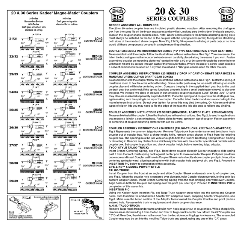
Kadee G Scale 835 User manual

Kadee

Kadee G Scale 835 User manual

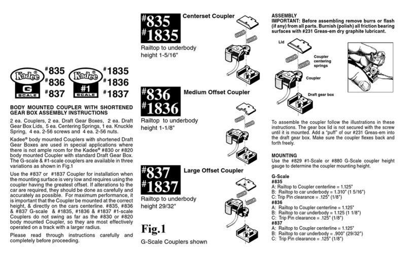
Kadee O-SCALE 811 User manual

Kadee

Kadee O-SCALE 811 User manual

Kadee The Coupler People Cushion 50 Foot PS-1 Box... User manual

Kadee

Kadee The Coupler People Cushion 50 Foot PS-1 Box... User manual

Kadee Magne-Matic HO Scale 21 User manual

Kadee

Kadee Magne-Matic HO Scale 21 User manual

Kadee G Scale 789 User manual

Kadee

Kadee G Scale 789 User manual

Kadee HO Scale Under The Ties 309 User manual

Kadee

Kadee HO Scale Under The Ties 309 User manual

Kadee MAGNE-MATIC 793 User manual

Kadee

Kadee MAGNE-MATIC 793 User manual

Kadee 708 Installation guide

Kadee

Kadee 708 Installation guide

Kadee 103 Instruction manual

Kadee

Kadee 103 Instruction manual

Popular Toy manuals by other brands

Radica Games 73025 instruction manual

Radica Games

Radica Games 73025 instruction manual

Mega Construx WONDER BUILDERS POKEMON Raichu manual

Mega Construx

Mega Construx WONDER BUILDERS POKEMON Raichu manual

Faller 951 manual

Faller

Faller 951 manual

Rapido Trains Amtrak NPCU F40PH Operator's manual

Rapido Trains

Rapido Trains Amtrak NPCU F40PH Operator's manual

Rolly Toys Snow-master Quick start manual

Rolly Toys

Rolly Toys Snow-master Quick start manual

REVELL McDonnell Douglas DC-10 Assembly manual

REVELL

REVELL McDonnell Douglas DC-10 Assembly manual

LEGO 8678 Assembly guide

LEGO

LEGO 8678 Assembly guide

Viessmann 5069 manual

Viessmann

Viessmann 5069 manual

marklin 37636 user manual

marklin

marklin 37636 user manual

marklin 37002 instruction manual

marklin

marklin 37002 instruction manual

Stevens Aero Model CAP 232 manual

Stevens Aero Model

Stevens Aero Model CAP 232 manual

Pro Boat Miss Elam Plus owner's manual

Pro Boat

Pro Boat Miss Elam Plus owner's manual

V-tech Bright Bunch PC user manual

V-tech

V-tech Bright Bunch PC user manual

Fisher-Price DWW12 quick start guide

Fisher-Price

Fisher-Price DWW12 quick start guide

V-tech CYBER SPY user manual

V-tech

V-tech CYBER SPY user manual

Fisher-Price P2255 instruction sheet

Fisher-Price

Fisher-Price P2255 instruction sheet

Carson POLICE TYRANN 230 GYRO 2.4 GHz instruction manual

Carson

Carson POLICE TYRANN 230 GYRO 2.4 GHz instruction manual

Step 2 Fiesta Cruise Sand and Water Table Assembly instructions

Step 2

Step 2 Fiesta Cruise Sand and Water Table Assembly instructions

manuals.online logo
manuals.online logoBrands
  • About & Mission
  • Contact us
  • Privacy Policy
  • Terms and Conditions

Copyright 2025 Manuals.Online. All Rights Reserved.