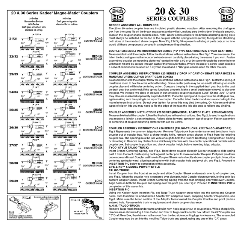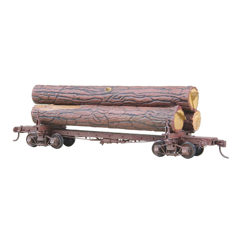
K-2 BRAKE SYSTEM: Be certain end of center sill (15) to bear brake wheel
has been identified. Begin by placing air tank (1) with tapered end toward
brake wheel end of car as seen in Fig. C, exploded view. Note that lever (2)
has a clevis projection to enter into end of air tank (see Fig. D). Fit these
together, then enter mounting studs of these parts into proper holes In center
sill (15). Do this once on a trial basis without cement to gain a better idea of
the procedure. Next, mounting studs of lever (3) are entered into holes In
car body and at the same time, Insert rod (5) into clevis openings of levers
(2) and (3) as seen In Figs. C and D. Use cement on the joined parts.
Dirt trap (4), briefly mentioned earlier, is to be detached from Its original
position as It comes joined to the triple valve on end of air tank (1). It Is to
be swung around to form a right angle with the air tank (Fig. D). Note also,
air line pipe (8) must pass through opening of tee on end of dirt trap piping
(4). One end angle of pre-bent pipe (8) can be reduced, using pliers, to allow
It to pass through dirt trap tee. When this has been done restore bend In
pipe to former angle. Slide dirt trap assembly along pipe (8) until correctly
positioned to cement free end of piping Into elbow on triple valve at end of
air tank (see Figs. C and D). Cement ends of (8) Into center sill.
A halt must be called In brake system assembly at this point. This Is because
two rods (7) and another rod (6) must pass through slots In cross bearers
(20A and 20B) of the truss system. This can be seen In Fig. L. Rod (6) must
also pass through an opening In the end bunk closest to the brake wheel
(Fig a.). These rods are to be added later.
Three staples (10) are supplied as supports, one for lever (3) and two for
lever (2), as seen In Fig. C. These can be Installed and cemented now.
ASSEMBLING TRUSS SYSTEM TO MODEL: Center stud projections of
end bunk assemblies (23) are entered into extreme outer ends of elongated
holes In center sill (15) so bunks are spread as far apart as possible. Flashing
may be found on sides of center stud, make sure these areas are clean
for a proper fit. Enter ends of truss rods (21) through holes in queen posts
(22), (Sea supplement Instruction sheet for further clarification’ feeding one
queen post onto each end of each pair of rods. Handle these rods carefully
since they will bend under pressure. Next, enter queen post shank pins into
holes In cross bearers (20A and 20B). Truss rods can be kept in alignment
much better If the piece of paper (supplied) Is entered through the open
turnbuckles across the complete set of rods. This prevents them from twisting
around temporarily, then the paper can be removed once rods are secured
Into end bunks. Now secure the rod ends Into the end slot of sill. (Refer to
supplementary Instruction data Fig. U-1). Place this whole truss assembly
on underside of center sill, being sure notches in the bearers fit properly
over pipe “8” and align the holes on truss system with the posts on center
sill (15). Once the truss system Is located on center sill, slide end bunks
(23) toward extreme Inner ends of elongated holes In center sill, capturing
the truss system between the two end bunks.
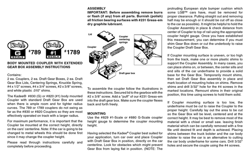
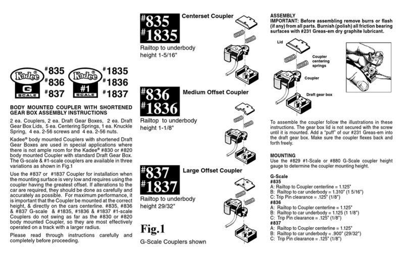
COUPLER AND DRAFT GEAR: Be sure
end castings (16 and 17) are clear of
flashing in all openings, especially where
the thin ends of the center sill enter these
castings. Note: End casting (16) bears a
ratchet assembly to carry the brake wheel,
this fits at car end earlier marked with a
letter “B”. Thus It Is properly placed to
accept the rod from the brake system. End
casting (17) without brake ratchet, naturally
fits the opposite end.
Now before proceeding further, flatten the
head of the short 1/2” common pin with a
pair of pliers. Thread It through the end link
of the 5/8” piece of chain as shown In Fig.
O. Next push pin all the way Into the hole on the Inside of end casting (16)
and out through the brake ratchet. Put brake wheel on exposed pin end and
cut off pin leaving about 1/16” protruding beyond brake wheel. With pliers,
pinch pin as close to brake wheel as possible to flare It, cut off just enough
of the flat so the wheel will not come off. (See Fig. O and Fig. P). Slide end
castings onto ends of center sill (see Fig. N). Once the couplers have been
fitted to the draft gear, enter these assemblies into end castings. Apply a
little Kadee
®
#231 “Greas-em”, burnishing and polishing will greatly reduce
friction of working parts and improve coupler performance. Assemble the
coupler as shown in Fig. R. Add #231 “Greas-em” to Inside of coupler unit
and work coupler back and forth. Be sure coupler consistently snaps back
to center position before continuing further. Slide assembled draft gear unit
into the end casting as shown in Fig. M and secure draft gear boxes to end
sills by Inserting pins (18) In mounting holes (see Fig. M and C). Position
rod (6) in holes In cross bearer (20B) and log bunk (23) but do not secure to
lever (2) yet. Now capture the end link of the 5/8” chain, from brake wheel,
with the looped end of brake rod (6). Close the loop with pliers to secure the
chain. Cement straight end of rod (6) Into clevis on lever 2 (see Fig. a and
Fig. C). Use our #205 or #206 coupler height gauge to check for the correct
height and trip pin clearance. The HO-Scale N.M.R.A. standard for coupler
height is the centerline of coupler at 25/64” (.390”). Use our #237 Trip Pin
Pliers to carefully adjust the trip pin clearance if necessary.
FINAL ASSEMBLY: The two brake rods (7) can now be entered through
slots In cross bearers so their straight ends cement Into clevis openings of
levers (2 and 3). The bent ends of rod cement into holes In center sill (see
Fig. L). Install two air pipes (9), one at each end of car, by entering straight
end of the rods into openings In end casting at rear of where air hoses (14)
are located, then enter bent end Into hole In center sill. All this can be seen
In Fig. a. To prevent wheels from hitting center sill (15) on extremely tight
radius curves, carefully scoop out wheel wells with a Sharp blade at the points
where wheels touch sill. Likewise, on extremely tight curves, the bearing
pad of truck frame could pass beyond corresponding pad on underside
ends of end bunks, thus they might stub and catch when returning from
the curve. To remedy this, file the top of truck bearing pad slightly round as
seen In Fig. C (Inset).
Now the two center bunks (24) can be installed In the holes on the side sills
(19) and across the center sill (15). These bunks are to be located directly
over the cross bearers (20A and 20B). Insert 2-56 screw (33) through truck
frame (32), then through king pin bearing plate (31) (with sprue removed)
and thread Into center stud of end bunks located In center sill (see Fig. C).
Finally, cement air hoses (14) Into openings at side of end castings (Fig. a).
Like this model !!! Then try our other super fine “Masters Builders” kits.
#102 Skeleton Log Flat Is the same as the #103 except It has no truss
system, and only two bunks. The #101 Disconnected Log Car Is a unique log
hauling arrangement. The #104 Industrial Caboose Is designed after logging
prototypes. All cars are equipped with Kadee
®
Magne-Matic
®
couplers.
3. Place glued end
over the knuckle
retaining post and
then compress
spring so that it
may slip over the
opposing shank
retaining post. See
Fig. 3.
4. Carefully
remove pic from
spring.
Fig. 2.
673 Avenue C
White City,
Oregon
97503- 1078 U.S.A.
© 2008 Kadee
®
Quality Products Co. 62008
Fig. 3.
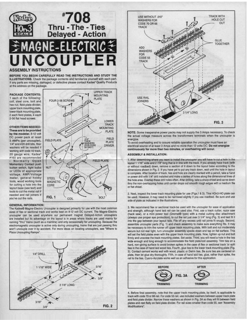
GLUING INSERT
To prevent losing knuckle springs by being
dislodged use the following steps and supplies.
Kadee®#241 Dual Tool (Manual Uncoupling Tool
& Spring Pic), small piece of blue denim cloth,
DUCO®CEMENT or WALT HERS®GOO®,or
similar type cement. CAUTION: Always follow
safety instructions for the cement that you may
be using.
1. To pick up spring place it on the cloth (this
allows the small springs to be seen and picked
up easier) and insert
#241 Dual To ol (Manual
Uncoupling Tool & Spring
Pic) into spring between
coils near one end. See
Fig. 1.
2. Touch one end of the spring into the cement
so that no more than one or two coils are
coated (too much cement will hamper coupler
performance). See Fig. 2.
Fig. 1.
WARNING:
CHOKING HAZARD - Small Parts
Not for children under 14 years.
Made Entirely
in the U.S.A.
071310
673 Avenue C,
white City, OR 97503-1078 © 2010, Kadee®Quality Products Co.
Quality Products Co.
7
8
22
623
19
23
Fig. L
details such as
stakes and chains
have been omitted
Fig. O
Fig. P
Fig. N
details such as stakes
and chain, truss system,
couplers and draft gear are
left out here for clarity.
916
14
Fig. Q
brake
rod (6)
passes
through
opening
in bunk
clean flashing from inside
of all openings so ends of
center sill and draft gear
may fit into end castings
with ease!
16
11
18
12
Fig. M
Fig. R
