manuals.online logo
Brands
  1. Home
  2. •
  3. Brands
  4. •
  5. Kadee
  6. •
  7. Toy
  8. •
  9. Kadee MAGNE-MATIC 793 User manual

Kadee MAGNE-MATIC 793 User manual

Note: One of the gear boxes has a large hole in
the shank and the other has been machined at an
angle on the shank. The coupler with the medium
offset is used with the draft gear box that has the
large hole located in its shank and will be mounted
at the front of the locomotive. See Fig.1. The coupler
with the large offset is used with the draft gear box
that has been machined and is to be mounted at the
rear of the locomotive. See Fig.2. When working on
locomotives or cars they must often be turned upside
down or on their sides. Always place a protective mat
underneath them, and protect any protruding detail
parts which could be damaged. Remove any flash or
burrs from parts with a file or an X-acto®knife.
MOUNTING
Front coupler:
1. Remove the old existing coupler.
2. Refer to the exploded view in Fig.3 to familiarize
yourself with coupler mounting parts and installation
positions. There are two large diameter washers in
this packet, one (1) thick and one (1) thin. Place the
thin washer onto the locomotive's coupler mounting
post and slide it down until it rests on top of the three
gussets located on the post. If the washer does
not slip onto the coupler mounting post there may
be excessive paint on the post. This paint can be
removed by scraping the post with an X-acto®knife.
The washer should not fit too loosely.
ASSEMB LY
IMPORTANT: Before assembling remove any
burrs or flash (if any) from all parts. Burnish
(Polish) all friction bearing surfaces with #231
Greas-em dry graphite lubricant.
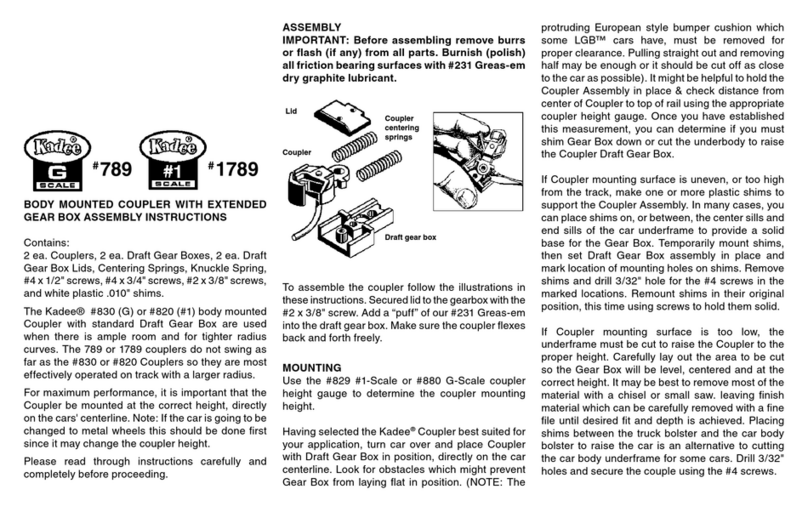
To assemble the coupler follow the illustrations in
these instructions. Make sure the gear box lid is
tightly secured with the screw. Add a “puff” of our
#231 Greas-em into the draft gear box. Make sure
the coupler flexes back and forth freely.
Lid Coupler
centering
springs
Coupler
Draft gear box
Screw
3. Slip the assembled coupler unit through the
opening of the locomotive pilot and tilt the coupler
unit at a slight angle to position the large hole in the
draft gear box shank over the mounting post. Slide
the shank down the post to rest on the thin washer
and then level coupler unit.
4. The thick washer can now be placed on the post
and over the previously installed draft gear box
shank.
5. Position the flat angle spring over the thick washer,
centering the hole in the spring leg over the original
coupler mounting screw hole in the post. Make
certain that the other spring leg is pointing down
behind the end of the draft gear box shank.
6. Place the small washer on top of the flat angle
spring and secure with the original coupler mounting
screw that was removed previously, Make certain
that the draft gear box is centered in the locomotive
pilot opening while tightening the mounting screw.
7. Test the centering action of the draft gear box; it
should move freely from side to side and re-center
itself. If the coupler unit does not center properly, it
may be helpful to loosen the mounting screw and
push slightly forward on the back leg of the flat angle
spring while retightening the screw. If the flat angle
spring does not tighten down properly, remove and
file one or both of the large washers until it will do so.
If more side swing of the coupler is desired, the sides
of the draft gear box or pilot opening at the front of
the locomotive can be modified by carefully cutting
or filing away the excessive material that interferes
with the desired swing. Caution must be exercised
against removing to much material. This would
impair the performance of the coupler.
793 / 1793 Ins.
Rear Coupler:
1. Remove the old existing coupler.
2. Place the new Kadee®coupler unit with the large
offset in the same position as the old coupler. Secure
with the previously remove 1 original mounting screw
or use the supplied No.4 x 3/8" screw.
3. If coupler drawbar does not re-center properly,
you may find excess paint on the coupler mounting
bracket guide wall as shown in Fig.4. This can be
scraped off with an X-acto®knife.
COUPLER OPERATION
TO COUPLE -
Simply push cars together until knuckles bypass
each other and lock into position.
FOR DELAYED UNCOUPLING -
1) Stop with the couplers over an uncoupler and back
up slightly with the couplers still over the uncoupler,
allowing slack to occur between couplers. 2) Pull
forward slightly. Couplers are now in the delayed
position. 3) Back up, pushing the car(s) to the desired
location. Do not permit slack to develop between
couplers. 4) Pull forward, leaving the car(s) where
desired. Couplers automatically return to normal
coupling position.
Use Kadee®Greas-em, the dry lubricant recommended
for use with all Kadee®Magne-Matic® couplers.
Grease-em will not attract the dirt and dust that
gums up the inside of couplers like oil, grease or
other lubricants will. Use our #829 #1-Scale or #880
G-Scale Height Gauge to check for the correct coupler
height and trip pin clearance. The N.M.R.A. standard
for coupler height is the centerline of coupler is 1 1/16”
(1.0625”)for #1-Scale & 1 1/8” (1.125”) G-Scale.
Note: We include extra knuckle springs. The
Replacement Knuckle Spring used on Kadee®
#1-Scale couplers are sold as the #875 (#819-828
couplers) or #1875 (1700 & 1800 series couplers)
Knuckle Spring. The Knuckle Spring used on Kadee®
G-Scale couplers are sold as the #860 Knuckle
Spring.
For Delayed Action Uncoupling use our #842
Uncoupler, #844 Portable Uncoupler, or our #840
Uncoupler mounted in LGB track.
Kadee®coupler conversion list & coupler
conversions are on the Kadee®web site for your
connivance.
www.kadee.com/conv/convpl.htm
©2007 Kadee®Quality Products Co.
081407
Made in the U.S.A.
673 Avenue C
White City, OR 97503
NOTE: If couplers swing open too far when
uncoupling, lower magnet slightly to correct.
Note: One of the gear boxes has a large hole in
the shank and the other has been machined at an
angle on the shank. The coupler with the medium
offset is used with the draft gear box that has the
large hole located in its shank and will be mounted
at the front of the locomotive. See Fig.1. The coupler
with the large offset is used with the draft gear box
that has been machined and is to be mounted at the
rear of the locomotive. See Fig.2. When working on
locomotives or cars they must often be turned upside
down or on their sides. Always place a protective mat
underneath them, and protect any protruding detail
parts which could be damaged. Remove any flash or
burrs from parts with a file or an X-acto®knife.
MOUNTING
Front coupler:
1. Remove the old existing coupler.
2. Refer to the exploded view in Fig.3 to familiarize
yourself with coupler mounting parts and installation
positions. There are two large diameter washers in
this packet, one (1) thick and one (1) thin. Place the
thin washer onto the locomotive's coupler mounting
post and slide it down until it rests on top of the three
gussets located on the post. If the washer does
not slip onto the coupler mounting post there may
be excessive paint on the post. This paint can be
removed by scraping the post with an X-acto®knife.
The washer should not fit too loosely.
ASSE MB LY
IMPORTANT: Before assembling remove any
burrs or flash (if any) from all parts. Burnish
(Polish) all friction bearing surfaces with #231
Greas-em dry graphite lubricant.
To assemble the coupler follow the illustrations in
these instructions. Make sure the gear box lid is
tightly secured with the screw. Add a “puff” of our
#231 Greas-em into the draft gear box. Make sure
the coupler flexes back and forth freely.
Lid Coupler
centering
springs
Coupler
Draft gear box
Screw
3. Slip the assembled coupler unit through the
opening of the locomotive pilot and tilt the coupler
unit at a slight angle to position the large hole in the
draft gear box shank over the mounting post. Slide
the shank down the post to rest on the thin washer
and then level coupler unit.
4. The thick washer can now be placed on the post
and over the previously installed draft gear box
shank.
5. Position the flat angle spring over the thick washer,
centering the hole in the spring leg over the original
coupler mounting screw hole in the post. Make
certain that the other spring leg is pointing down
behind the end of the draft gear box shank.
6. Place the small washer on top of the flat angle
spring and secure with the original coupler mounting
screw that was removed previously, Make certain
that the draft gear box is centered in the locomotive
pilot opening while tightening the mounting screw.
7. Test the centering action of the draft gear box; it
should move freely from side to side and re-center
itself. If the coupler unit does not center properly, it
may be helpful to loosen the mounting screw and
push slightly forward on the back leg of the flat angle
spring while retightening the screw. If the flat angle
spring does not tighten down properly, remove and
file one or both of the large washers until it will do so.
If more side swing of the coupler is desired, the sides
of the draft gear box or pilot opening at the front of
the locomotive can be modified by carefully cutting
or filing away the excessive material that interferes
with the desired swing. Caution must be exercised
against removing to much material. This would
impair the performance of the coupler.
793 / 1793 Ins.
Rear Coupler:
1. Remove the old existing coupler.
2. Place the new Kadee®coupler unit with the large
offset in the same position as the old coupler. Secure
with the previously remove 1 original mounting screw
or use the supplied No.4 x 3/8" screw.
3. If coupler drawbar does not re-center properly,
you may find excess paint on the coupler mounting
bracket guide wall as shown in Fig.4. This can be
scraped off with an X-acto®knife.
COUPLER OPERATION
TO COUPLE -
Simply push cars together until knuckles bypass
each other and lock into position.
FOR DELAYED UNCOUPLING -
1) Stop with the couplers over an uncoupler and back
up slightly with the couplers still over the uncoupler,
allowing slack to occur between couplers. 2) Pull
forward slightly. Couplers are now in the delayed
position. 3) Back up, pushing the car(s) to the desired
location. Do not permit slack to develop between
couplers. 4) Pull forward, leaving the car(s) where
desired. Couplers automatically return to normal
coupling position.
Use Kadee®Greas-em, the dry lubricant recommended
for use with all Kadee®Magne-Matic® couplers.
Grease-em will not attract the dirt and dust that ©2007 Kadee®Quality Products Co.
081407
Made in the U.S.A.
673 Avenue C
White City, OR 97503
NOTE: If couplers swing open too far when
uncoupling, lower magnet slightly to correct.
gums up the inside of couplers like oil, grease or
other lubricants will. Use our #829 #1-Scale or #880
G-Scale Height Gauge to check for the correct coupler
height and trip pin clearance. The N.M.R.A. standard
for coupler height is the centerline of coupler is 1 1/16”
(1.0625”)for #1-Scale & 1 1/8” (1.125”) G-Scale.
Note: We include extra knuckle springs. The
Replacement Knuckle Spring used on Kadee®
#1-Scale couplers are sold as the #875 (#820-828
couplers) or #1875 (1700 & 1800 series couplers)
Knuckle Spring. The Knuckle Spring used on Kadee®
G-Scale couplers are sold as the #860 Knuckle
Spring.
For Delayed Action Uncoupling use our #842
Uncoupler, #844 Portable Uncoupler, or our #840
Uncoupler mounted in LGB track.
Kadee®coupler conversion list & coupler
conversions are on the Kadee®web site for your
connivance.
www.kadee.com/conv/convpl.htm

This manual suits for next models

1

Other Kadee Toy manuals

Kadee 708 Installation guide

Kadee

Kadee 708 Installation guide

Kadee HO Scale Under The Ties 309 User manual

Kadee

Kadee HO Scale Under The Ties 309 User manual

Kadee G Scale 789 User manual

Kadee

Kadee G Scale 789 User manual

Kadee Magne-Matic HO Scale 21 User manual

Kadee

Kadee Magne-Matic HO Scale 21 User manual

Kadee 102 User manual

Kadee

Kadee 102 User manual

Kadee 103 Instruction manual

Kadee

Kadee 103 Instruction manual

Kadee The Coupler People Cushion 50 Foot PS-1 Box... User manual

Kadee

Kadee The Coupler People Cushion 50 Foot PS-1 Box... User manual

Kadee O-SCALE 811 User manual

Kadee

Kadee O-SCALE 811 User manual

Kadee G Scale 835 User manual

Kadee

Kadee G Scale 835 User manual

Popular Toy manuals by other brands

SIG Antoinette 1909 manual

SIG

SIG Antoinette 1909 manual

Mega Bloks STAR TREK DPH80 manual

Mega Bloks

Mega Bloks STAR TREK DPH80 manual

Horizon Hobby E-Flite HABU STS instruction manual

Horizon Hobby

Horizon Hobby E-Flite HABU STS instruction manual

Mikado Logo 600 manual

Mikado

Mikado Logo 600 manual

Fisher-Price LittlePeople K7925 quick start guide

Fisher-Price

Fisher-Price LittlePeople K7925 quick start guide

RadioLink A560 instruction manual

RadioLink

RadioLink A560 instruction manual

Hasbro Transformers Armada 7052 owner's manual

Hasbro

Hasbro Transformers Armada 7052 owner's manual

Eduard ZOOM SS 658 manual

Eduard

Eduard ZOOM SS 658 manual

THE WORLD MODELS Groovy 90 instruction manual

THE WORLD MODELS

THE WORLD MODELS Groovy 90 instruction manual

RavensBlight MANOR Assembly instructions

RavensBlight

RavensBlight MANOR Assembly instructions

Lionel AMERICAN FLYER EP-5 owner's manual

Lionel

Lionel AMERICAN FLYER EP-5 owner's manual

roco BB 26000 SNCF operating manual

roco

roco BB 26000 SNCF operating manual

Trix MINITRIX 16125 manual

Trix

Trix MINITRIX 16125 manual

OYO Sports GAMETIME HOCKEY RINK instructions

OYO Sports

OYO Sports GAMETIME HOCKEY RINK instructions

Summer 06536 instruction manual

Summer

Summer 06536 instruction manual

Hobbywing Technology HYPE DG-1001M instruction manual

Hobbywing Technology

Hobbywing Technology HYPE DG-1001M instruction manual

Eduard Hetzer mid production Assembly instructions

Eduard

Eduard Hetzer mid production Assembly instructions

Smoby FRENCH TOUCH manual

Smoby

Smoby FRENCH TOUCH manual

manuals.online logo
manuals.online logoBrands
  • About & Mission
  • Contact us
  • Privacy Policy
  • Terms and Conditions

Copyright 2025 Manuals.Online. All Rights Reserved.