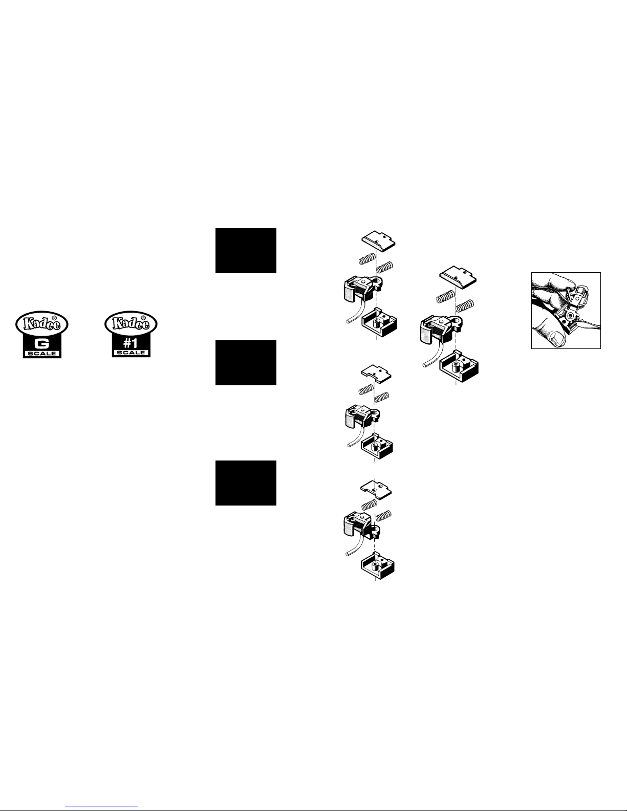
Fig.1
Railtop to underbody
height 1-1/8"
#835
#837
#836
Railtop to underbody
height 1-5/16"
#835
#1835
#1835
#1837
#1836
Centerset Coupler
#836
#1836
Medium Offset Coupler
Railtop to underbody
height 29/32"
#837
#1837
Large Offset Coupler
G-Scale Couplers shown
ASSEMBLY
IMPORTANT: Before assembling remove burrs or flash
(if any) from all parts. Burnish (polish) all friction bearing
surfaces with #231 Greas-em dry graphite lubricant.
To assemble the coupler follow the illustrations in these
instructions. The gear box lid is not secured with the screw
until it is mounted. Add a “puff” of our #231 Greas-em into
the draft gear box. Make sure the coupler flexes back and
forth freely.
MOUNTING
Use the #829 #1-Scale or #880 G-Scale coupler height
gauge to determine the coupler mounting height.
G-Scale
#835
A: Railtop to Coupler centerline = 1.125"
B: Railtop to car underbody = 1.310" (1 5/16")
C: Trip Pin clearance = .125" (1/8")
#836
A: Railtop to Coupler centerline = 1.125"
B: Railtop to car underbody = 1.125 (1 1/8")
C: Trip Pin clearance = .125" (1/8")
#837
A: Railtop to Coupler centerline = 1.125"
B: Railtop to car underbody = .900" (29/32")
C: Trip Pin clearance = .125" (1/8")
Lid
Coupler
centering
springs
Coupler
Draft gear box
BODY MOUNTED COUPLER WITH SHORTENED
GEAR BOX ASSEMBLY INSTRUCTIONS
2 ea. Couplers, 2 ea. Draft Gear Boxes, 2 ea. Draft
Gear Box Lids, 5 ea. Centering Springs, 1 ea. Knuckle
Spring, 4 ea. 2-56 screws and 4 ea. 2-56 nuts.
Kadee
®
body mounted Couplers with shortened Draft
Gear Boxes are used in special applications where
there is not ample room for the Kadee
®
#830 or #820
body mounted Coupler with standard Draft Gear Box.
The G-scale & #1-scale couplers are available in three
variations as shown in Fig.1
Use the #837 or #1837 Coupler for installation when
the mounting surface is very low and requires using the
coupler having the greatest offset. If alterations to the
car are required, they should be done as carefully and
accurately as possible. For maximum performance, it
is important that the Coupler be mounted at the correct
height, & directly on the cars centerline. #835, #836
& #837 G-scale & #1835, #1836 & #1837 #1-scale
Couplers do not swing as far as the #830 or #820
body mounted Coupler, so they are most effectively
operated on a track with a larger radius.
Please read through instructions carefully and
completely before proceeding.
#1-Scale
#1835
A: Railtop to Coupler centerline = 1.062" (1 1/16")
B: Railtop to car underbody = 1.310" (1 5/16")
C: Trip Pin clearance = .125" (1/8")
#1836
A: Railtop to Coupler centerline = 1.062" (1 1/16")
B: Railtop to car underbody = 1.125 (1 1/8")
C: Trip Pin clearance = .125" (1/8")
#1837
A: Railtop to Coupler centerline = 1.062" (1 1/16")
B: Railtop to car underbody = .900" (29/32")
C: Trip Pin clearance = .125" (1/8")
Having selected the Kadee
®
Coupler best suited for your
application, turn car over and place Coupler with Draft
Gear Box in position, directly on the car centerline. Look
for obstacles which might prevent Gear Box from laying flat
in position. (NOTE: The protruding European style bumper
cushion which some LGB™ cars have, must be removed
for proper clearance. Pulling straight out and removing half
may be enough or it should be cut off as close to the car as
possible). It might be helpful to hold the Coupler Assembly
in place & check distance from center of Coupler to top of
rail using the appropriate coupler height gauge. Once you
have established this measurement, you can determine if
you must shim Gear Box down or cut the underbody to raise
the Coupler Draft Gear Box.
If Coupler mounting surface is uneven, or too high from the
track, make one or more plastic shims to support the Coupler
Assembly. In many cases, you can place shims on, or
between, the center sills and end sills of the car underframe
to provide a solid base for the Gear Box. Temporarily mount
shims, then set Draft Gear Box assembly in place and mark
location of mounting holes on shims. Remove shims and drill
and tap for 2-56 screws in the marked locations. Remount
shims in their original position, this time using screws to hold
them solid.
NOTE: When using metal screws in plastic, tapping of the hole is not
required. After drilling a 5/64" hole, the screw will self-tap.
If Coupler mounting surface is too low, the underframe must
be cut to raise the Coupler to the proper height. Carefully
lay out the area to be cut so the Gear Box will be level,
centered and at the correct height. It may be best to remove
most of the material with a chisel or small saw. leaving finish
material which can be carefully removed with a fine file until
desired fit and depth is achieved. Placing shims between
the truck bolster and the car body bolster to raise the car is
an alternative to cutting the car body underframe for some
cars.
The Coupler Assembly can now be screwed into place. An
alternative to tapping the mounting holes is to drill 3/32"
holes through and use 2-56 screws and nuts to secure the
Draft Gear Box. The metal screws can be cut to the required
length with a fine saw. Before cutting, screw on a supplied
nut, so that by removing it after the cutting, the nut will serve
to clean up the thread ends.
COUPLER OPERATION
TO COUPLE -
Simply push cars together until knuckles bypass each other
and lock into position.
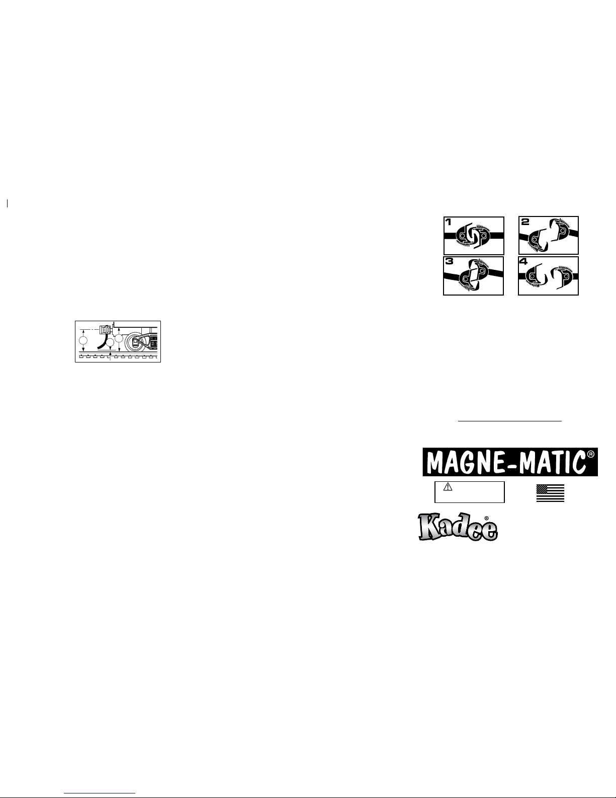
FOR DELAYED UNCOUPLING -
1) Stop with the couplers over an uncoupler and back up
slightly with the couplers still over the uncoupler, allowing
slack to occur between couplers. 2) Pull forward slightly.
Couplers are now in the delayed position. 3) Back up,
pushing the car(s) to the desired location. Do not permit
slack to develop between couplers. 4) Pull forward, leaving
the car(s) where desired. Couplers automatically return to
normal coupling position.
Use Kadee
®
Greas-em, the dry lubricant recommended for
use with all Kadee
®
Magne-Matic
®
couplers. Grease-em will
not attract the dirt and dust that gums up the inside of couplers
like oil, grease or other lubricants will. Use our #829 #1-Scale
or #880 G-Scale Height Gauge to check for the correct coupler
height and trip pin clearance. The N.M.R.A. standard for
coupler height is the centerline of coupler is 1 1/16” (1.0625”)
for #1-Scale & 1 1/8” (1.125”) G-Scale.
NOTE: If couplers swing open too far when
uncoupling, lower magnet slightly to correct.
Note: We include extra knuckle springs. The Replacement
Knuckle Spring used on Kadee
®
#1-Scale couplers are sold as
the #875 (#820-828 couplers) or #1875 (1700 & 1800 series
couplers) Knuckle Spring. The Knuckle Spring used on Kadee
®
G-Scale couplers are sold as the #860 Knuckle Spring.
For Delayed Action Uncoupling use our #842 Uncoupler,
#844 Portable Uncoupler, or our #840 Uncoupler mounted
in LGB track.
Kadee
®
coupler conversion list & coupler conversions are
on the Kadee
®
web site for your connivance.
www.kadee.com/conv/convpl.htm
673 Avenue C,
White City, OR 97503-1078
© 2009, Kadee®Quality Products Co.
012909
Made & Assembled Entirely
in the U.S.A.
Quality Products Co.
WARNING:
CHOKING HAZARD - Small Parts
Not for children under 14 years.
CB
A