manuals.online logo
Brands
  1. Home
  2. •
  3. Brands
  4. •
  5. KAEL
  6. •
  7. Controllers
  8. •
  9. KAEL DV-72-RR User manual

KAEL DV-72-RR User manual

DV – 72 - RR
General Informations:
Used for servo motors to keep the output voltage at the desired set value.
- The device measures both the input voltage and the output voltage and keeps the output voltage
constant by controlling the servo motor control output.
- Calculates measurements using the True RMS method.
- Interferes ith the motor speed.
- Stores in memory the lo est and highest over voltage values of the input voltage.
This can be follo ed by the manufacturer's operating conditions.
BUTTONS :
By pressing the up key you can reach the measurement screen with
the input overvoltage value,
By pressing the down key you can see the Input undervoltage value.
INTRODUCTION TO PARA ETERS:
Press the set button for 5 seconds.
Set: In this menu, you can access follo ing parameters ith key button: Set, h-1, h-2, Spd, Pou, Clr, uSt,
Alt, hYS, dLY-oFF, dLY-on and qut. When Set menu is accessed all parameters flash on the screen. To change
parameter value, first press the set key, then change the value ith the direction keys. Press set key to store the desired value.
qut : Press Set to return to the measurement screen.
USING THE KEYS:
The Set menu is entered ith the set key. The parameters in the menu can be accessed ith the arro keys. Enter the parameters ith the Set key
and change the value ith the arro keys. With the Set key, the parameter hich value has been changed is memorized.
TRUE R S
REGULATOR CONTROLLER
■ % Input Overvoltage SET value max. limit should be selected lo er than the
open-circuit voltage value.
Sample :
If the s itch limit is set as 250 volts, the% input Overvoltage SET value
should be ≤ 249 V.
■ % Output Lo voltage SET value min. limit should be selected higher than
open-circuit voltage value
Sample :
If the s itch limit is set as 170 volts, the% undervoltage SET value
should be ≥ 171 volts. Other ise, it gives Engine error (dEr). In this case,
the output opens the relay contact. When the voltage returns to the normal
values, (dEr) the engine failure occurs and the device brings the output
voltage of the regulator to the set value. The output relay turns the contact off.
V(in)
Input Voltage(V)
TRIAC output (motor
drive circuit) t
Permissible voltage range
V(out)
Output Voltage (V)
(Re) t
t
dLY
on
dLY
oFF
dLY
oFF
dLY
on
dLY
on
Normal
region
Overvoltage
input set value
% Hysteresis
>>>> value
% Hysteresis
>>>> value
UnderVoltage
input SET Value
(Over) S itch on
voltage rating
(Lo ) S itch on
voltage rating
Control according to input voltage:
■ Output voltage due to overload, due to voltage pulse,
% output Overvoltage SET value or % output Lo voltage SET value,
If the dLY exceeds the oFF time, the device opens the relay contact. When
the output voltage returns to% hYS and dLY is actie, the device turns off the
relay contact.
■ It is advisable to select the set values as follo s.
Overvoltage
output set value
% Hysteresis
>>>> value
Undervoltage
output set value
% Hysteresis
>>>> value
Output Relay
Control according to output voltage
>
<
Connection Scheme :
TECHNICAL DATA:
Rated Voltage (Un) : 220 VAC
Operating Range : (0.8 – 1.1)xUn
Frequency : 50 Hz
Supply Po er Consumption : < 4 VA
Measurement Sensitivity : 1% + digit
Display : T o lines of 3 Digits LED display
Motor Driver Output : 12 – 15 Vac
Contact Current : Max. 5A / 240 Vac
Device Protection Class : IP20
Connector Protection Class : IP00
Temperature : -5°C....+50°C
Humidity : 15% ...... 95% ( ithout condensation)
Connection Type : To front panel tap
Dimensions : 72x72x80 mm
Warning !!!
- The message Er1 or Er2 on the screen means that the device has got
a failure
- Clean the device using dry dustcloth after de-energizing the device
t
Output voltage
SET value
Normal range
here the engine
is not operated
Speed zone
access
V
Max. Speed zone
Access to Output Voltage:
± Normal
range value
± Normal
range value
± Speed control zone
Max. Speed zone
Speed zone
access
SET
Increase
Decrease
SET
SET
Increase
Decrease
Press SET button untill SEt
shows up on the screen.
SET
Increase
Decrease
SET
Increase
Decrease
SET
SET
Increase
Decrease
SET
Increase
Decrease
SET
Increase
Decrease
SET
Increase
Decrease
SET
Increase
Decrease
SET EXIT
SET
SET
Increase
Decrease
Motor or Device
Connection Fault
000 : Fault Control Off
001 : Fault Control On
Output voltage
SET value
(80 – 400 V)
± Normal range value
(0,1 – 10 V)
defines the non-motorized
zone.
example :: 0.5
220 + 0.5 = 220.5 V
220 - 0.5 = 219.5 V
Speed (motor speed)
SET value (1 – 5 )
Set motor speed to ensure
smooth transition.
min speed = 1
Openning Time
SET value (0,01 – 60 sec)
This time counts for opening
hen excessive or lo er
limit is reached.
± Speed control zone
(0,1 – 10 V)
Slo motor speed region
determined to provide soft
transition to setpoint
Exit
% Under voltage
SET value (0,05 -0,50)
220 x (1-0.26) = 163 V
Closing Time
SET value (0,01 – 60 sec)
At the end of this time the
output is released hen
the voltage returns to the
normal value.
% Over voltage SET value
(0,05 -0,50)
220 x (1+0,12) = 246 V
SET
Increase
Decrease
Engine Power Balance
(30 – 140 )
It helps to find the ideal po er usage of different motors.
For non-impact operation
SET
Increase
Decrease
%Output Overvoltage
SET value (0,05 -0,50)
220 x (1+0,12) = 246 V
SET
Increase
Decrease
%Output Under voltage
SET value (0,05 -0,50)
220 x (1-0.26) = 163 V
L1
N
Output Contact
5A / 240Vac
V in V out V out N SW1 SW2 Vac
12-15
VARIAC
(Variable
Transformer)
12V
DC
motor
3Ω 11W
0
12V
Auxiliary supply
% Hysteresis value for
Openning- Closing
Overvoltage;
246 x (1-0.01)=244V
Undervoltage;
163 x (1-0.01)=161V

Other KAEL Controllers manuals

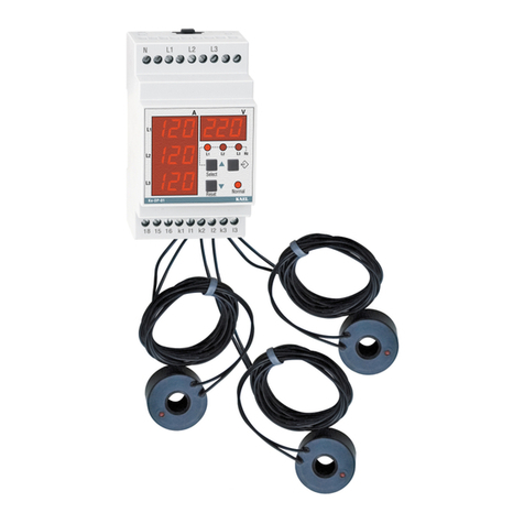
KAEL ke-DP01 User manual

KAEL

KAEL ke-DP01 User manual

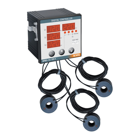
KAEL ke-DP01-100A User manual

KAEL

KAEL ke-DP01-100A User manual

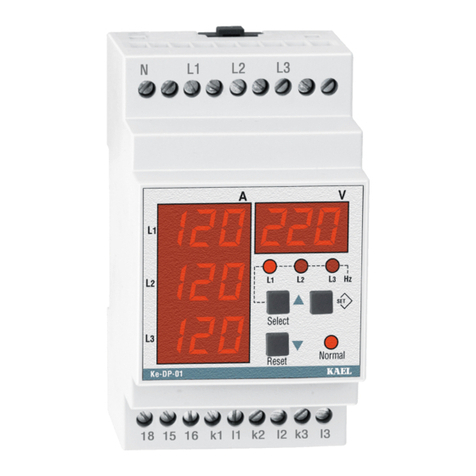
KAEL DP01-72 User manual

KAEL

KAEL DP01-72 User manual

Popular Controllers manuals by other brands

M-Elec C-V870 instruction manual

M-Elec

M-Elec C-V870 instruction manual

Aerotech APR200DR Series Hardware manual

Aerotech

Aerotech APR200DR Series Hardware manual

MRC PRODIGY EXPLORER instructions

MRC

MRC PRODIGY EXPLORER instructions

IAI PCON-CY Operation manual

IAI

IAI PCON-CY Operation manual

Mitsubishi Electric CR800 Series Special Specifications Manual

Mitsubishi Electric

Mitsubishi Electric CR800 Series Special Specifications Manual

WesAudio RHEA manual

WesAudio

WesAudio RHEA manual

eZLO Atom Advanced information

eZLO

eZLO Atom Advanced information

Chauvet Power Panel PC-08 user guide

Chauvet

Chauvet Power Panel PC-08 user guide

LEUCHTWURM 43LED/526 quick start guide

LEUCHTWURM

LEUCHTWURM 43LED/526 quick start guide

Honeywell HEGSA002 User manual                                              user manual

Honeywell

Honeywell HEGSA002 User manual user manual

Eaton ELC-CODNET instruction manual

Eaton

Eaton ELC-CODNET instruction manual

John Gold GoldCruise GC55 installation manual

John Gold

John Gold GoldCruise GC55 installation manual

Wahsega InformaCast user guide

Wahsega

Wahsega InformaCast user guide

Omron sysmac EtherNet/IP NJ Series Connection guide

Omron

Omron sysmac EtherNet/IP NJ Series Connection guide

Hacker HST-120 operating manual

Hacker

Hacker HST-120 operating manual

Siemens ATC5300 operating instructions

Siemens

Siemens ATC5300 operating instructions

Full Gauge Controls Evolution MT-530E Super manual

Full Gauge Controls

Full Gauge Controls Evolution MT-530E Super manual

Emerson PACSystems RX3i user manual

Emerson

Emerson PACSystems RX3i user manual

manuals.online logo
manuals.online logoBrands
  • About & Mission
  • Contact us
  • Privacy Policy
  • Terms and Conditions

Copyright 2025 Manuals.Online. All Rights Reserved.